Centrifugal pump brand crn 32 2
Various types of centrifugal pumps are widely used in main and autonomous networks - for supplying and discharging water, drainage, increasing pressure, irrigation and watering. In addition, they have found application in various industries, agriculture, engineering industries, food and chemical industries. The choice of unit is made based on the specific conditions of its operation. Next, you will be offered instructions on the topic: “Classification of centrifugal pumps,” and the video in this article will help you understand the design features of this or that type of hydraulic equipment.
Two main characteristics of a circulation pump
With a long list of technical characteristics of heat pumps, there are two main ones. This is the diameter of the connection pipes and the power of the “accelerator”. These two numbers are considered decisive and are indicated in the name.
Connection pipe diameter
The most important parameter for pump installation, especially with already installed heating systems. This is a numerical value indicated in millimeters and indicating the diameter of the heating pipes that can be connected to the inlet/outlet pipes.
Please note that for connection to the body pipes, taps are made with threaded threads.
Power
Power in heating systems is the ability to raise water to a certain height or pump pressure.
In the marking of Grundfos pumps, the power is indicated in meters multiplied by 10 or atmospheres multiplied by 100. That is, Grundfos with the ability to raise water by 5 meters (pressure 5 meters), the marking will receive the figure 50 or 0.5 atm. (atmospheres).
Example: Circulation pump Wilo Star 30/2, means that the diameter of the connection pipes is 30 mm, the pressure is 2 meters.
In Wilo markings, power is indicated simply in meters.
Example: Grundfos UPS 25 40 (130 mm), means that the diameter of the connection pipes is 25 mm (1/2 inch), the pressure is 4 meters. 130 is the installation length.
Marking of centrifugal pumps
The pump-building industry of our country produces hundreds of a wide variety of centrifugal pumps for various purposes. In order to quickly and correctly select a centrifugal pump for specific production needs, several designation systems have been developed.
The marking of pumps of the normal series is carried out in the following form: the first digit is the diameter of the suction pipe in mm, reduced by 25 times and rounded; followed by letters that indicate: N - oil, G - hot; D – first wheel of two-way input; B – vertical; K – console; CE – cantilever, mounted in one block with an electric motor; M – multi-stage. The second figure is the speed coefficient or specific speed, reduced by 10 times and rounded. The third number is the number of steps; letters at the end of the marking: K – acidic; C – for liquefied gases.
Examples of designation and marking of pumps:
8NG-10x2 – centrifugal pump, suction pipe diameter 200 mm, oil, hot (for liquid with a temperature of 220–400 °C), speed factor 100, number of stages 2.
8NGK-10x1 – centrifugal pump, suction pipe diameter 200 mm, oil, hot, cantilever, speed factor 100, number of stages 1.
14NGD-10x3 – centrifugal pump, suction pipe diameter 350 mm, oil, hot, first wheel of double inlet.
8ND-10x5 – centrifugal pump, suction pipe diameter 200 mm, oil (temperature < 220 °C), first wheel of double inlet, speed factor 100, number of stages 5.
3x10ND-9x3 – centrifugal pump for main oil and product pipelines, three pumps are connected in series, suction pipe diameter 250 mm, oil (temperature < 220 °C), first wheel of double-sided inlet, speed factor 90, number of stages 3. speed factor 100, number of steps 3.
In addition, pumps are marked according to basic technical indicators: flow and pressure. Most pumps are marked as follows: after the letter designation (brand), two numbers are placed separated by a dash or slash - the nominal flow, m3/h, and the nominal pressure, m of liquid column.
Examples of symbols: a cantilever pump with a flow of 125 m3/h and a head of 30 m is designated as follows: K 125 - 30 or K 125/30, and a horizontal fecal pump with the same indicators is FG 125 - 30 or FG 125/30.
Pump brand K 20/18-5-U3: 20 – flow, m3/h; 18 – head, m.
Multistage sectional pumps are designated CNS. For example, brand CNS 180-212: CNS – centrifugal sectional pump; flow Q=180 m3/h; head H =212 m.
Centrifugal pump K65-50-160/2 The pump designation means: K – cantilever; 65-50 – feed in m3/h when turning the impeller; 160 – head in m; 2 – modernization index.
The following markings are also used: Pump brand KM 65-50-160a/2-5-U3:
KM – horizontal console monoblock pump; 65 – diameter of the inlet pipe, mm; 50 – diameter of the outlet pipe, mm; 160 – nominal diameter of the impeller, mm; a – symbol of the impeller with turning, ensuring the operation of the unit in the middle part of the “QH” field; 2 – symbol of the number of revolutions of the electric motor:
– 2 at n=2900 rpm;
– 4 at n=1450 rpm;
5 – single mechanical seal; U3 – climatic version and placement category during operation according to GOST 15150-69; P – fire-fighting version with a soft stuffed gland.
Pump brand KM 50-32-200:
50 – diameter of the inlet pipe, mm; 32 – diameter of the outlet pipe, mm; 200 – nominal impeller diameter, mm.
Today the following letter designation of general purpose pump brands is accepted:
K – single-stage cantilever pump;
B – pump, single-stage, vertical, cantilever;
D – single-stage pump with a double-sided impeller;
CNS – sectional multistage pump;
CN – multistage pump;
VK – vortex pump, cantilever;
CV – centrifugal vortex pump;
SVN – self-priming vortex pump.
Operating principle and design of centrifugal pumps
Operating principle.
The centrifugal pump is shown schematically in Figure 2.98. In a cast-iron spiral housing 1, a shaft 8 rotates, driven by an electric motor, a steam turbine, or an internal combustion engine (directly or through a V-belt drive). An impeller 3 with blades is attached to the shaft, the spaces between which form channels for the passage of liquid.
1 – body; 2 – suction fitting; 3 – impeller; 4 – discharge fitting;
5 – valve; 6 – check valve; 7 – pressure gauge; 8 – shaft; 9 – vacuum gauge;
10 – intake valve with mesh
Figure 2.98 – Centrifugal pump
There are two fittings in the housing - 2 and 4. One of them is located along the horizontal axis of the housing (its axis lies on the continuation of the shaft axis), and the other is tangential to the housing spiral, at the point of its greatest distance from the center. The first fitting is used to introduce liquid into the pump (a suction pipeline is attached to it), the second is a discharge one.
A valve 5 is installed on the discharge pipeline, which serves to shut off the pipeline and regulate the pump performance. A check valve 6 is located above it. When the pump suddenly stops, it prevents the reverse flow of liquid and thereby protects the pump from hydraulic shock, which can cause pump failure. At the end of the suction pipeline, immersed in liquid, a suction valve 10 is installed, which prevents liquid from flowing out of the suction pipeline and the pump when the latter is stopped.
If the internal space of the pump and its suction pipeline are filled with liquid, then when the impeller rotates, the blades entrain the liquid, and the resulting centrifugal force throws it into the spiral channel (the so-called “volute”) of the housing. Moving along the channel, the liquid enters the discharge fitting and from it into the discharge pipeline. As a result of the release of the transported liquid into the discharge pipeline, a vacuum is created in the suction cavity, and the liquid from the tank or apparatus being emptied begins to rise in the suction pipe into the pump. Thus, the process of uniform pumping of liquid is established.
The pressure (pressure) developed by centrifugal force in an operating pump is directly proportional to the square of the impeller speed.
Schematically, a centrifugal pump consists of an impeller 4 (Figure 2.99), equipped with blades and installed on a shaft 1 in a spiral casing 5. The flow diagram of fluid in the pump casing is shown in Figure 2.100.
| 1 – shaft; 2 – discharge pipe; 3 – blade; 4 – impeller; 5 – housing Figure 2.99 – Scheme of a centrifugal pump | 1 – body; 2 – impeller Figure 2.100 – Diagram of fluid flow in the pump housing |
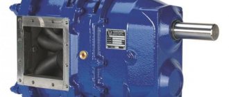
Despite the wide variety of designs, centrifugal pumps (Figure 2.101) consist of the following main components and parts: housing, rotor with impeller, bearings, end shaft seals, impeller seals, couplings.
Figure 2.101 – Centrifugal single-span horizontal multistage pump with an axial connector and a side liquid inlet with a volute casing
What is a BP/BP connection?
The detachable connection BP/BP of the heating system is a set of adapters that allows you to connect the pipe to the pump body.
- BP/BP means nut/nut;
- BP/HP means nut/thread.
BP/BP adapters are used to connect circulation pumps. Here is an example: Photo of an adapter for connecting a BP/BP pump (1 1/2″ - 1″). This means that the pump nut has a diameter of one and a half inches (32 mm), and the pipe connection nut has an inch (25 mm) diameter.
On the nameplate of the pump and in its description, the diameter G is often indicated; this is the diameter of the union nut for the pump. Pumps are sold complete with connection adapters.
Note: Threaded connection of circulation pumps is typical for low-power household pumps. More powerful pumps are connected via flange connections.
Selection of pump according to technical parametersMore about the program
In this article you will learn in general how to determine the parameters necessary in any particular case. Let's look at the problems and their solutions. You do not have to take advice from sellers of certain pumps. And if you are a novice professional in water supply and heating systems, then this article will serve as a good guide to pumps.
This is a universal pump selection technique
. There are a huge number of brands and types of pumps, and dozens of times more parameters.
Using my pump selection method, you will learn:
And of course, don’t forget about the reserve. You never know that the water level in the well will suddenly change due to high flow rates or the season.
A more detailed calculation for calculating parameters for well pumps is here: How to calculate the pressure of a well pump?
Regarding consumption
, then the calculation is based on two main values:
| 1. Consumption at the point of consumption. 2. Pressure loss through the pipeline from the pump to the point of consumption at the mixer or tap. |
As for water consumption, there is approximately a ready-made digital standard. Let's take the bathroom faucet for example. I have experimentally verified that for a comfortable water flow at the outlet it is approximately equal to: 0.25 liters per second. We will take this value as a standard for selecting a diameter for a water flow.
But, if we have one pump for the entire water supply system. Then it is necessary to calculate the total flow for all consumption points. It is advisable to find the average indicator when the maximum inclusion of all water consumption devices is possible. Sum up all expenses and find some approximate average expense.
Let's assume we have two bathrooms and a kitchen. And let’s imagine, for example, that the maximum of all consumption is two baths and a kitchen, including a hot stream, we find: A maximum of 6 points of consumption at one time. This means we multiply the average of 0.25 liters per second by 6 points and get: 1.5 liters per second, which is equal to: 90 liters per minute.
It is approximately from this calculation that you select the required pump flow rate.
It is important to maintain the required pipe diameter at certain pipeline velocities. About this in the article: Choosing the diameter of a pipe for water supply.
Also keep in mind that in rare cases it is desirable to calculate the head loss when water moves in the pipeline at certain speeds. If this is important for someone, then include in the calculation the pressure and pressure loss at certain water velocities in the pipeline. Since the higher the speed of water movement in the pipeline, the stronger the water resists movement in the pipeline. About this in the article: Hydraulic calculation for pressure loss.
Watch the video:
Buy the program
As for the types of pumps.
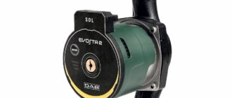
Circulation pump
– the pump is designed for heating systems, for constant continuous movement of water. Typically, such a pump is not designed for high pressure, since it is not intended to raise water to a certain height, but only to circulate it. So if your house is high and the last circuit in the heating system is more than 40 meters high from the pump itself, then a pump with a pressure of only 2 meters is able to circulate, but provided that there is no air in the heating system that can interfere with circulation. But there is one caveat! It is necessary to take into account the pressure loss during circulation, and only then select what pressure is needed for the system. I will say that selecting the pressure here is also elementary. It is necessary to know the flow rate in the system at which it is necessary to push water and calculate the pressure loss. And the pump pressure must be equal to the pressure loss. How to calculate speeds and pressure losses in closed heating systems will be discussed in other articles.
Pumps for water supply.
Water supply pumps are not designed to pump water constantly. Turning on and off as needed. Usually such pumps are needed for a well. There are piston and rotary pumps. Piston pumps are cheap, they are usually low pressure pumps and are only for simple use. There is a very big drawback: they vibrate and make a lot of noise.
A rotary pump is the best thing that can be used on a regular basis for a well; they do not make noise and have good pressure. I personally recommend a submersible rotary pump for a well! This is the best thing on the market! In a rotary pump, there are rotating blades that set the water in motion.
Also regarding the characteristics between flow and pressure. The faster the water moves without loss, the less pressure it produces. The pressure on the pump is maximum when the pump is running and the water is not pumping. That is, the taps are closed and the pump is running, but the outlet is closed. This law states that the higher the pressure loss in a pipe to the point of consumption, the less water it pumps. Well, don’t worry too much, this distortion is almost small, but it’s still there. And the greater the pressure loss in the pipe, the more energy is spent pumping water. And it takes a lot of energy to pump water. Keep this in mind.
Write comments...
Next article: Professional calculation of water heating systems. Calculation of heat loss of the water circuit.
| Like |
| Share |
| Comments (+) [ Read / Add ] |
All about the country house Water supply Training course. Automatic water supply with your own hands. For Dummies. Malfunctions of the well automatic water supply system. Water wells Well repair? Find out if you need it! Where to drill a well - outside or inside? In what cases does cleaning a well make no sense Why pumps get stuck in wells and how to prevent it Laying a pipeline from a well to a house 100% Protecting the pump from dry running Heating Training course. Do-it-yourself water heated floor. For Dummies. Warm water floor under laminate Educational Video course: According to HYDRAULIC AND THERMAL CALCULATIONS Water heating Types of heating Heating systems Heating equipment, heating batteries Heated floor system Personal article on heated floors Operating principle and operating diagram of a heated water floor Design and installation of a heated floor Do-it-yourself water heated floor Basics materials for heated water floors Installation technology of water heated floors System of heated floors Laying step and methods of laying heated floors Types of water heated floors All about coolants Antifreeze or water? Types of coolants (antifreeze for heating) Antifreeze for heating How to properly dilute antifreeze for the heating system? Detection and consequences of coolant leaks How to choose the right heating boiler Heat pump Features of a heat pump Heat pump operating principle About heating radiators Methods of connecting radiators. Properties and parameters. How to calculate the number of radiator sections? Calculation of thermal power and number of radiators Types of radiators and their features Autonomous water supply Scheme of autonomous water supply Construction of a well Cleaning a well with your own hands Experience of a plumber Connecting a washing machine Useful materials Water pressure reducer Hydraulic accumulator. Operating principle, purpose and configuration. Automatic air release valve Balancing valve Bypass valve Three-way valve Three-way valve with ESBE servo drive Thermostat for radiator Manifold servo drive. Selection and connection rules. Types of water filters. How to choose a water filter for water. Reverse osmosis Sludge filter Non-return valve Safety valve Mixing unit. Principle of operation. Purpose and calculations. Calculation of the CombiMix Gidrostrelka mixing unit. Operating principle, purpose and calculations. Indirect heating storage boiler. Principle of operation. Calculation of a plate heat exchanger Recommendations for the selection of PHE when designing heat supply facilities About contamination of heat exchangers Indirect water heating water heater Magnetic filter - protection against scale Infrared heaters Radiators. Properties and types of heating devices. Types of pipes and their properties Indispensable tools for a plumber Interesting stories A scary tale about a black installer Water purification technologies How to choose a filter for water purification Let's think about sewerage Sewage treatment plants in a rural house Tips for a plumber How to evaluate the quality of your heating and plumbing system? Professional recommendations How to choose a pump for a well How to properly equip a well Water supply for the garden How to choose a water heater An example of installing equipment for a well Recommendations for the configuration and installation of submersible pumps What type of water supply accumulator should you choose? Water cycle in an apartment - vent pipe Removing air from a heating system Hydraulics and heating engineering Introduction What is hydraulic calculation? Physical properties of liquids Hydrostatic pressure Let's talk about resistance to the passage of liquid in pipes Modes of liquid movement (laminar and turbulent) Hydraulic calculation of pressure loss or how to calculate pressure loss in a pipe Local hydraulic resistance Professional calculation of pipe diameter using formulas for water supply How to select a pump according to technical parameters Professional calculation of water heating systems. Calculation of heat loss of the water circuit. Hydraulic losses in a corrugated pipe Heat engineering. Author's speech. Introduction Heat transfer processes Thermal conductivity of materials and heat loss through the wall How do we lose heat with ordinary air? Laws of thermal radiation. Radiant warmth. Laws of thermal radiation. Page 2. Heat loss through a window Factors of heat loss at home Start your own business in the field of water supply and heating systems Question on hydraulic calculations Designer of water heating Pipe diameter, flow speed and coolant flow. We calculate the diameter of the heating pipe. Calculation of heat losses through the radiator. Power of the heating radiator. Calculation of the power of radiators. Standards EN 442 and DIN 4704 Calculation of heat loss through building envelopes Find heat loss through the attic and find out the temperature in the attic Selecting a circulation pump for heating Transfer of thermal energy through pipes Calculation of hydraulic resistance in a heating system Distribution of flow and heat through pipes. Absolute schemes. Calculation of a complex associated heating system Heating calculation. Popular myth Calculation of heating of one branch along the length and KMS Calculation of heating. Selection of pump and diameters Heating calculation. Two-pipe dead-end Heating calculation. Single-pipe sequential heating calculation. Two-pipe associated Calculation of natural circulation. Gravity pressure Calculation of water hammer How much heat is generated by pipes? We are assembling a boiler room from A to Z... Heating system calculation Online calculator Calculation program Heat loss of the room Hydraulic calculation of pipelines History and capabilities of the program - introduction How to make a calculation of one branch in the program Calculation of the KMS angle of the outlet Calculation of the KMS of heating and water supply systems Pipeline branching - calculation How to calculate in the program single-pipe heating system How to calculate a two-pipe heating system in a program How to calculate radiator flow in a heating system in a program Recalculation of radiator power How to calculate a two-pipe associated heating system in a program. Tichelman loop Calculation of a hydraulic separator (hydraulic arrow) in the program Calculation of a combined circuit of heating and water supply systems Calculation of heat loss through enclosing structures Hydraulic losses in a corrugated pipe Hydraulic calculation in three-dimensional space Interface and control in the program Three laws/factors for selecting diameters and pumps Calculation of water supply with self-priming pump Calculation of diameters from the central water supply Calculation of water supply for a private house Calculation of a hydraulic arrow and collector Calculation of a hydraulic arrow with many connections Calculation of two boilers in a heating system Calculation of a single-pipe heating system Calculation of a two-pipe heating system Calculation of a Tichelman loop Calculation of a two-pipe radial distribution Calculation of a two-pipe vertical heating system Calculation of a single-pipe vertical heating system Calculation of a warm water floor and mixing units Recirculation of hot water supply Balancing adjustment of radiators Calculation of heating with natural circulation Radial distribution of a heating system Tichelman loop - two-pipe associated Hydraulic calculation of two boilers with a hydraulic arrow Heating system (not Standard) - Another piping scheme Hydraulic calculation of multi-pipe hydraulic arrows Radiator mixed system heating - passing from dead ends Thermoregulation of heating systems Pipeline branching - calculation Hydraulic calculation for pipeline branching Calculation of a pump for water supply Calculation of warm water floor contours Hydraulic calculation of heating. Single-pipe system Hydraulic heating calculation. Two-pipe dead-end Budget option for a single-pipe heating system for a private house Calculation of the throttle washer What is KMS? Calculation of a gravity heating system Designer of technical problems Extension of a pipe Requirements SNiP GOSTs Requirements for a boiler room Question for a plumber Useful links for a plumber - Plumber - ANSWERS!!! Housing and communal problems Installation work: Projects, diagrams, drawings, photos, descriptions. If you're tired of reading, you can watch a useful video collection on water supply and heating systems
Grundfos circulation pump markings
Decoding the brand (Type) of the grundfos pump:
- UP – circulation;
- S – there is a power (rotation speed) switching;
- D – twin;
- 30 – diameter (mm dn) of the suction pipe and pressure pipe;
- 60 – max. pressure (meters×10);
- F – connection of pipes through a flange (the letter is missing when threaded);
- N – body material (cast iron body – no letter, letter N – stainless steel body);
- B – bronze body;
- A – the housing has an air outlet;
- K – housing for working with antifreeze (special version).
Design
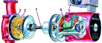
The unit consists of a pump and an electric motor mounted on a common frame. The pump is driven from the engine through an elastic coupling.
Fig. 2 – Electric motor The main parts of the pump are:
- pump housing
- lid
- bearing housing
- shaft
- angular contact ball bearings
- radial roller bearing
- shaft seal
- Working wheel
- screw wheel
- shaft nut.
Fig. 3 – internal structure of the pump The pump body is made together with support legs, inlet and outlet pipes.
Fig. 4 – pump housing
The cover is attached using studs with nuts and washers. The joint between the body and the cover is sealed with a spirally wound gasket. The housing cover at the point where the shaft exits has a stuffing box for installing a seal. The seal prevents leakage of the pumped liquid through the gap between the shaft and the housing cover.
The pump housing, pump cover and bearing housing have holes for inlet and outlet of sealing and coolant fluid from the pump.
By the way, read this article too: Vane Pump
Fig. 5 – system for supplying and discharging sealing and cooling fluid from the pump
The pump shaft rotates in two bearing supports. The support located at the coupling consists of two angular contact ball bearings. They face each other with the wide sides of the outer rings. To prevent axial movement on the shaft, the inner rings of the bearings are secured with a washer and a nut. With their help, the gear coupling half with the spacer sleeve is simultaneously attached. The second support consists of one radial roller bearing.
Bearings are lubricated by circulation and are carried out from a common oil bath.
impeller consists of rear and front disks, between which blades are installed. The blades are bent from the radial direction in the direction opposite to the direction of rotation of the impeller. The impeller and screw wheels are mounted on the cantilever part of the shaft and secured with a nut with a left-hand thread.
