Total, static and dynamic pressure. Measuring pressure in air ducts of ventilation systems
Total, static and dynamic pressure
When air moves through an explosive in any cross section, 3 types of pressure are distinguished:
Static pressure
determines the potential energy of 1 m 3 of air in the section under consideration.
It is equal to the pressure on the walls of the air duct. .
Dynamic pressure
– kinetic energy of the flow per 1 m3 of air.
– air density, – air speed, m/s.
Total pressure
equal to the sum of static and dynamic pressure.
It is customary to use the value of excess pressure, taking atmospheric pressure at the system level as a conditional zero. In discharge air ducts, total and static excess pressure is always “+”, i.e. pressure >
. In the suction air ducts, the total and static excess pressure is “-”.
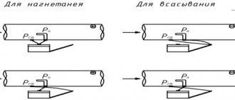
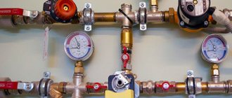
Measuring pressure in air ducts of ventilation systems
The pressure in the explosive is measured using a pneumometric tube and some measuring device: a micromanometer or other device.
For plenum duct:
static pressure – static pressure tube to the micromanometer tank;
total pressure – full pressure tube to the micromanometer tank;
dynamic pressure - the total pressure tube to the tank, and static pressure - to the capillary of the micromanometer.
For suction duct:
static pressure – static pressure tube to the pressure gauge capillary;
total pressure – total pressure tube to the capillary of the micromanometer;
dynamic pressure - the total pressure tube to the tank, and static pressure - to the capillary of the micromanometer.
Schemes for measuring pressure in air ducts.
Ticket No. 10
Pressure losses in ventilation systems
When moving along an explosive, air loses its energy to overcome various resistances, i.e. pressure loss occurs.
Friction pressure loss
– coefficient of friction resistance. Depends on the mode of movement of liquid through the air duct. — kinematic viscosity, depends on temperature.
In laminar mode:
in turbulent motion
depends on the roughness of the pipe surface. Various formulas are used and the Altschul formula is widely known: – absolute equivalent roughness of the material of the inner surface of the air duct, mm.
For sheet steel 0.1mm; silicate concrete slabs 1.5 mm; brick 4 mm, plaster on mesh 10 mm
Specific pressure loss
In engineering calculations, special tables are used in which the values are given
for round duct. For air ducts made of other materials, a correction factor is introduced and is equal to: .
Correction factor value
is given in the reference book depending on the type of material and the speed of air movement through the air duct.
For rectangular air ducts, the calculated value d is taken to be equivalent to dek, at which the pressure loss in a round air duct at the same speed will be equal to the pressure loss in a rectangular air duct:
— sides of a rectangular duct.
It should be kept in mind: the air flow of rectangular and round air ducts with
when the speeds are equal, it does not coincide.
Date added: 2018-02-18; ;
Source
Reference point: absolute and relative pressure, differential pressure
Pressure measurements in everyday life, such as measuring tire pressure, are usually carried out relative to the ambient air pressure. In other cases, pressure is measured relative to a vacuum or some other reference point. When considering pressure reference points, the following concepts are used:
- Absolute pressure
is measured relative to an ideal vacuum and is equal to the sum of relative pressure (instrument pressure) and atmospheric pressure. - Relative pressure
(instrument pressure) is measured relative to the ambient air pressure and is equal to the difference between absolute pressure and atmospheric pressure. The minus sign is usually omitted. - Pressure difference
is the difference in pressure at two points.
The pressure reference point is usually clear from the context and is stated only when clarification is necessary. Tire pressure and blood pressure are usually relative by definition, while barometric pressure, high vacuum pressure, and altimeter pressure are absolute. Differential pressure is often used in industrial installations. Differential pressure meters have two inlets, each connected to a vessel whose pressure must be controlled. In effect, such a meter performs a mathematical subtraction operation, eliminating the need for an operator or monitoring system to monitor two separate meters and determine the difference in readings. Small vacuum pressure values are often ambiguous because they can represent absolute or relative pressure without a minus sign. Thus, a relative vacuum pressure of 26 inches of mercury is equivalent to an absolute vacuum pressure of 30 (mean atmospheric pressure) inches of mercury. – 26 inches Hg. = 4 Hg
Atmospheric pressure is generally taken to be 100 kPa at sea level, but can vary with altitude and weather. If the absolute value of the pressure of a liquid remains constant, then the relative pressure of the same liquid will change depending on the change in atmospheric pressure. For example, when a car drives up the side of a mountain (atmospheric pressure drops), the relative pressure in the tires rises. Some standard values for atmospheric pressure have been defined, such as 101.325 kPa or 100 kPa. Some instruments may use one of these values as a reference point instead of the actual ambient air pressure. This reduces the accuracy of these instruments, especially when used at high altitudes.
When atmospheric pressure is used as a reference point, the unit of measurement is usually followed by the letter g, for example - 30 psi (pounds per square inch) g. This means that the measured pressure is equal to the difference between absolute and atmospheric pressure. There are two types of setting the zero (reference) value for the meter: for a ventilated device and for a hermetically sealed meter.
For a vented meter, the pressure sensor allows external air pressure to be applied to the negative side of the pressure sensing diaphragm through a vented cable or hole in the meter so that the meter always measures pressure relative to atmospheric pressure. Therefore, the pressure sensor of a ventilated appliance should always measure zero pressure so that air is allowed to enter.
For a hermetically sealed meter, the procedure is very similar, except that the negative side of the diaphragm is hermetically sealed. This is typically used for high pressure instruments, such as hydraulics, where the effect of changes in atmospheric pressure on the accuracy of the instrument is negligible, so ventilation is not necessary. This also allows some manufacturers to provide an additional containment shell as another precaution in case the burst pressure of the main sensing membrane is exceeded.
There is another way to set the zero value of a hermetically sealed meter - on the back of the sensing membrane. In this case, the output signal is shifted so that the pressure sensor readings when measuring atmospheric pressure are close to zero.
The sensor reading when setting the zero value for a hermetically sealed meter will never be exactly equal to zero, since atmospheric pressure is constantly changing and the quality of the zero value in this case is set to a pressure of 1 bar.
The measurement of absolute pressure is related to the concept of absolute vacuum. The best example of an absolute reference pressure is atmospheric or barometric pressure.
When manufacturing absolute pressure sensors, the manufacturer creates a high vacuum behind the sensing membrane. If there is air access to the MAP sensor connection, the sensor will display the current barometric pressure value.
Bernoulli's equation. Static and dynamic pressure
STATE MEDICAL UNIVERSITY OF SEMEY
Methodological guide on the topic:
Study of the rheological properties of biological fluids.
Methods for studying blood circulation.
Main questions of the topic:
- Bernoulli's equation. Static and dynamic pressure.
- Rheological properties of blood. Viscosity.
- Newton's formula.
- Reynolds number.
- Newtonian and Non-Newtonian fluid
- Laminar flow.
- Turbulent flow.
- Determination of blood viscosity using a medical viscometer.
- Poiseuille's law.
- Determination of blood flow speed.
- Total resistance of body tissues. Physical foundations of rheography. Rheoencephalography
- Physical foundations of ballistocardiography.
Bernoulli's equation. Static and dynamic pressure.
Ideal is incompressible and has no internal friction or viscosity; stationary or steady flow is a flow in which the velocities of fluid particles at each point of the flow do not change over time. Steady flow is characterized by streamlines—imaginary lines that coincide with the trajectories of particles. Part of the fluid flow, bounded on all sides by stream lines, forms a stream tube or jet. Let us select a current tube so narrow that the particle velocities V in any of its sections S, perpendicular to the tube axis, can be considered the same throughout the entire section. Then the volume
liquid flowing through any section of the tube per unit time remains constant, since the movement of particles in the liquid occurs only along the axis of the tube: .
This relationship is called the jet continuity condition
It follows that for a real liquid with steady flow through a pipe of variable cross-section, the amount Q of liquid flowing per unit time through any section of the pipe remains constant (Q = const) and the average flow velocities in different sections of the pipe are inversely proportional to the areas of these sections: and t . d.
Pressure units
| Pascal (Pa, Pa) | Bar (bar, bar) | Technical atmosphere (at, at) | Physical atmosphere (atm, atm) | Millimeter of mercury (mm Hg, mmHg, Torr, torr) | Pound-force per sq. inch (psi) | |
| 1 Pa | 1 N/m2 | 10−5 | 10,197·10−6 | 9,8692·10−6 | 7,5006·10−3 | 145,04·10−6 |
| 1 bar | 105 | 1·106 dynes/cm2 | 1,0197 | 0,98692 | 750,06 | 14,504 |
| 1 at | 98066,5 | 0,980665 | 1 kgf/cm2 | 0,96784 | 735,56 | 14,223 |
| 1 atm | 101325 | 1,01325 | 1,033 | 1 atm | 760 | 14,696 |
| 1 mmHg | 133,322 | 1,3332·10−3 | 1,3595·10−3 | 1,3158·10−3 | 1 mmHg | 19,337·10−3 |
| 1 psi | 6894,76 | 68,948·10−3 | 70,307·10−3 | 68,046·10−3 | 51,715 | 1 psi |
The SI unit of pressure is the pascal, which is equal to one newton per square meter (Nm-2 or kgm-1 s-2). The official name of this unit was adopted in 1971, and before that pressure, according to SI, was measured in N m-2. When indicating pressure values, it is indicated in parentheses after the units of measurement whether the value is relative or absolute. For example - 101 kPa (abs.). The pressure unit pound per square inch (psi) is still widely used in the United States and Canada, for example when measuring tire pressure. Often a letter is added to the designation of these units to indicate the reference point of the measurement: psia for absolute values, psig for relative values, psid for pressure drop, although this is not encouraged by the National Institute of Standards and Technology.
Because pressure has traditionally been measured by its ability to change the height of a column of liquid in a pressure gauge, pressure is often measured in units of the height of a column of a particular liquid (such as inches of water). The most commonly used are mercury (Hg) and water; water is non-toxic and widely available, and the density of mercury allows pressure to be measured using a column of smaller volume (i.e., the pressure gauge will be more compact).
The density of liquids and gravity can vary depending on local factors, so the height of the liquid column does not always allow pressure to be measured accurately enough. If pressure values are currently reported anywhere in "millimeters of mercury" or "inches of mercury", these values do not imply the existence of a real column of mercury and may be expressed in SI units. Units based on the height of the water column are related to one of the original definitions of the kilogram as the mass of one liter of water.
Despite the disapproval of modern measurement specialists, these units of pressure are still used in many fields. Blood pressure is measured in millimeters of mercury in most countries around the world, and lung pressure is measured in centimeters of water. Pressure in gas pipelines is measured in inches of water, these units are indicated as 'inch WC' ('Water Column'). Scuba divers use a simple rule of thumb: the pressure at a depth of 10 meters is approximately equal to one atmosphere. In vacuum systems, pressure is primarily measured in millimeters, micrometers, and inches of mercury. Absolute pressure is usually measured in millimeters and micrometers, and relative pressure in inches.
Atmospheric pressure is usually expressed in kilopascals (kPa) or atmospheres, however, meteorologists in the United States prefer hectopascals (hPa) and millibars (mbar). In the United States and Canada, in engineering calculations, voltage is often measured in kilopounds (kip is short for kilopound). However, voltage is not equivalent to pressure because it is not a scalar quantity. In the CGS system (centimeter-gram-second), the unit of measurement of pressure was called “barrier” (ba) and was equal to 1 dyne cm−2. In the MTS system (meter-ton-second), the unit of pressure was the pieza, equivalent to 1 wall per square meter.
Many hybrid units are also used, such as mmHg/cm² or gram-force/cm² (sometimes as kg/cm² or g/mol2 without specifying the units of force). The use of the names “kilogram-force” and “gram-force” is unacceptable in the SI system, since the SI unit of force is newton (N).
Static and dynamic pressure
Static pressure is uniform in all directions, so the choice of direction does not matter when measuring the pressure of a stationary (static fluid). The flow, however, creates additional pressure on surfaces perpendicular to the direction of flow, and has almost no effect on surfaces parallel to the direction of flow. This direction-dependent component of pressure in a moving (dynamic) fluid is called dynamic pressure. A device that determines the direction of flow measures the sum of static and dynamic pressure. This value is called total or total pressure. Since dynamic pressure is compared to static pressure, it is not absolute or relative, but, in fact, a pressure difference.
Relative static pressure is of primary importance in determining the load on the pipe walls. Dynamic pressure is used to calculate the flow of gases and liquids, as well as the speed of air flows. Dynamic pressure can be measured as the difference between the readings of instruments placed in the flow parallel and perpendicular to it. For example, pitot tubes are used for similar measurements in aircraft testing. The presence of measuring instruments will inevitably affect the flow direction and may create turbulence, so their shape is critical to the accuracy of the measurements. Their calibration characteristics are often nonlinear.
Devices measuring static and dynamic pressure
- Altimeter (altimeter)
- Barometer
- Manifold pressure sensor
- Pitot tube
- Sphygmomanometer
Pressure measuring instruments
Numerous pressure measuring instruments have different advantages and disadvantages. The pressure range, sensitivity, dynamic response, and cost of different pressure measurement instruments often differ by several orders of magnitude. The very first of these devices, the liquid pressure gauge, was invented by Evangelista Torricelli in 1643. The U-shaped tube was created by Christiaan Huygens in 1661.
Hydrostatic
The basis of hydrostatic instruments (for example, liquid pressure gauges) is to compare pressure with the hydrostatic force acting per unit area of the base of a liquid column. Pressure measurement using hydrostatic instruments does not depend on the type of fluid used; such devices have a linear measurement scale. They have a weak dynamic response.
Deadweight piston
Weight-piston devices for measuring pressure balance the pressure of a liquid or gas with a jet (for example, pressure gauges for measuring tire pressure of relatively low accuracy) or with a solid load; such instruments are called load testers and are used to check the correct calibration of other pressure gauges.
Liquid
A liquid pressure gauge consists of a vertical column of liquid in a U-shaped tube. The liquid in both legs of the tube is under pressure of varying degrees. The column rises or falls depending on the pressure difference at the two ends of the tube. The simplest version of such a pressure gauge is a U-shaped tube with liquid, one end of which is connected to the vessel in which the pressure is to be measured, and the liquid in the second is under a predetermined pressure (possibly atmospheric or vacuum). Based on the difference in fluid levels, the effective pressure can be determined. Pressure from a liquid column of height h
and density
ρ
is calculated using the hydrostatic formula
P
=
hgρ
.
It follows that the difference between the effective pressure Pa
and the predetermined pressure
P
0 in a U-shaped liquid pressure gauge can be determined by solving the equation
Pa
−
P
0 =
hgρ
.
In other words, the pressure on the liquid column at each end of the tube must be balanced (since the liquid is static), hence Pa
=
P
0 +
hgρ
. If the fluid being measured is of significant density, hydrostatic corrections may be necessary when measuring the height of the manometer fluid column and the point where the pressure is to be measured, unless measuring a differential pressure (for example, using an orifice plate or venturi). In this case, the density ρ must be corrected by subtracting the density of the liquid whose pressure is being measured.
Any liquid can be selected for use in a liquid pressure gauge, but in most cases it is mercury, which has a high density (13.534 g/cm3) and a low vapor pressure. Water is also often used ("inches of water" is a common unit of measurement for pressure). Measuring pressure with liquid pressure gauges does not depend on the type of liquid used; such devices have a linear measurement scale. They have a weak dynamic response. When measuring vacuum, the working fluid may evaporate and fill the vacuum if its vapor pressure is too high. When measuring the pressure of different liquids, a piece of tubing filled with gas or light liquid can isolate the liquids from each other to prevent them from mixing, but this may not be necessary, for example, if mercury is used as the working fluid when measuring water pressure. Simple liquid pressure gauges can measure pressures ranging from a few millimeters of mercury (about 100 Pa) to several atmospheres (1,000,000 Pa).
A single-scale liquid pressure gauge has a large reservoir instead of one of the tube elbows and a graduation scale on the narrow part (the tube itself). The tube can be tilted to enhance fluid movement. Depending on the area of use and design, there are the following types of pressure gauges:
- Simple pressure gauge
- Micromanometer
- Differential pressure gauge (differential pressure gauge)
- Inverted differential pressure gauge.
McLeod vacuum gauge
A McLeod vacuum gauge isolates a sample of gas and compresses it using a slightly modified mercury manometer until the gas pressure reaches a few millimeters of mercury. The state of the gas must be stable during compression (for example, it must not condense). The technique takes a lot of time and is inconvenient for constant observations, but at the same time it is highly accurate.
Measuring pressure range
: from more than 10-4mm Hg. (about 10-2 Pa) up to 10−6 mm Hg. (0.1 mPa), with 0.1 mPa being the lowest pressure value that can be directly measured at this stage of technology development. Other vacuum gauges can measure smaller values, but only indirectly using other pressure measurement methods. These indirect measurements are converted to SI units by direct measurements, mainly using a McLeod vacuum gauge.
Aneroid
Aneroid
measuring instruments consist of a pressure-sensitive metal element that flexes under the influence of differential pressure. "Aneroid" means "without liquid," and the term is used to distinguish this class of instruments from the hydrostatic pressure gauges described above. However, aneroids can be used to measure pressure in both liquids and gases, and are not the only type of measuring instrument that does not use liquid. Therefore, they are now often called mechanical pressure meters. The type of gas whose pressure is being measured does not affect pressure measurements using aneroids (unlike thermal conductive and ionization instruments). Also, aneroids cannot contaminate the test substance, as can happen with hydrostatic devices. The pressure sensing element can be a Bourdon tube, diaphragm or bellows; these elements change shape under the influence of pressure at the point under study. The deflection or deflection of this element can be read using a needle or other transducer. The most common transducers record changes in electrical capacitance due to mechanical bending. Capacitive devices are called baratrons.
Bourdon tube pressure gauge
The Bourdon tube pressure gauge uses the following principle: a bent tube tends to straighten and increase its diameter under the influence of internal pressure. However, the change in diameter may be almost imperceptible, so at moderate stresses within the elastic deformation range of easily processed materials, the stress in the metal from which the tube is made is increased by giving the tube a C shape or even a flat spiral so that the entire tube tends to straighten or unwind under the influence pressure.
Eugene Bourdon patented this device in France in 1849. The Bourdon pressure gauge is widely used due to its very high sensitivity, simplicity and accuracy. In 1852, Edward Ashcroft acquired a patent to manufacture the device in America and became the main manufacturer of Bourdon pressure gauges. Also, in 1849, in the German city of Magdeburg, Bernard Schaeffer successfully patented a membrane pressure gauge, which, along with the Bourdon pressure gauge, revolutionized industrial pressure measurements. But in 1875, after Bourdon's patent expired, pressure gauges with a Bourdon tube also began to be produced.
Measuring pressure using a Bourdon tube looks like this: a flattened, thin-walled tube, sealed on one side, is connected at the open end to a fixed vessel containing the liquid whose pressure is to be measured. As the pressure increases, the sealed end of the tube describes an arc, a system of levers and gears converts this movement and drives a small diameter drive gear, to which the indicator arrow is connected. The location of the dial behind the arrow, the ability to set the initial position of the arrow, the length and initial position of the connecting parts - all this allows you to calibrate the device and measure the desired pressure range. The pressure difference can be measured using an instrument with two different Bourdon tubes interlocked.
Bourdon tube pressure gauges measure pressure relative to atmospheric pressure; measuring vacuum pressure looks like moving in the opposite direction. Some aneroid barometers use Bourdon tubes sealed at both ends (but most have diaphragms or bellows). The connecting tube has a restriction hole in case the measured pressure changes quickly (for example, during pump operation), to avoid wear of parts. If the instrument is subject to vibration, the housing may be filled with oil or glycerin, including the pointer and scale.
It is not recommended to tap the meter dial as this may degrade the accuracy of the current reading. The Bourdon tube is located separately from the dial and this will not affect the actual pressure value. Modern high-quality pressure gauges provide an accuracy of ± 2%, and special high-precision instruments provide ± 0.1% of the scale range.
The following illustrations show the pressure/vacuum combination meter removed from the housing and with the clear dial cover removed. Such combined devices are used for vehicle diagnostics.
- The left side of the dial, used to measure engine manifold vacuum, has units of measurement - centimeters of mercury on the inner scale and inches of mercury on the outer scale.
- The right side of the dial, indicating fuel pump pressure, shows kilograms per square centimeter on the inner scale and pounds per square inch on the outer scale.
Device details
Fixed parts:
- A: Receiving unit. Connects the tube coming from the liquid container to the fixed end of the Bourdon tube (1) and protects the base of the dial (B). Bolts are screwed into two holes to hold the housing.
- B: Dial base. The dial is attached to it. There are holes made in it for the axles.
- C: Additional dial base. The outer ends of the axles are attached to it.
- D: Pins connecting the bases of the dial.
Moving parts:
- The fixed end of a Bourdon tube. Interacts with a tube coming from a vessel with liquid through the receiving block.
- The sealed movable end of a Bourdon tube.
- Hinge and hinge axis.
- An element connecting the hinge axis to the lever, with axes allowing their joint rotation.
- Lever arm. Part of the gear sector.
- Gear sector axis.
- Gear sector.
- Instrument arrow axis. It has a gear wheel that rotates the gear sector and, passing through the dial, rotates the arrow of the instrument. Due to the small distance between the lever arm bushing and the hinge axis, as well as the difference between the effective diameters of the gear sector and the gear wheel of the device, the effect of any movement of the Bourdon tube is increased many times over. Small movements of the tube are converted into visible movements of the instrument needle.
- A hair spring that preloads the gear train to avoid tooth lag and play.
Diaphragm gauges
The second type of aneroid measuring instruments uses flexible diaphragms to separate areas of different pressure. Under pressure, the diaphragm bends. The amount of deflection is constant for known pressures, so the pressure can be measured by calibrating the diaphragm. The deformation of a thin diaphragm depends on the difference between the pressure values on its surfaces. One of the surfaces can be open to atmospheric air, then the second will show relative pressure. The pressure difference can be measured if the pressure on one side of the diaphragm is known. If a vacuum is created on one side of the diaphragm, then absolute pressure can be measured on the other. The amount of diaphragm deflection can be measured using mechanical, optical or capacitive methods. Diaphragms are made of metal and ceramic.
Measuring pressure range
: more than 10-2 mmHg. (about 1 Pa)
To measure absolute pressure values, sealed capsules with a diaphragm on one of the surfaces are used.
Diaphragm shapes:
- flat
- corrugated
- flattened tubes
- capsules
Bellows pressure gauges
In pressure gauges designed to measure small values of absolute pressure or pressure differences, the gear and pointer of the device are driven by changes in the volume of the membrane chamber (bellows). These pressure gauges are also aneroid (“without liquid,” in contrast to previously invented liquid instruments for measuring pressure, which use a column of liquid - water or mercury in a vacuum). Bellows are part of the design of aneroid barometers (barometers with a circular dial and pointer), altimeters, barographs and altitude meters used on weather radiosondes. Such devices use the pressure of a sealed chamber as a reference point for measuring external pressure. Sensitive instruments used in aviation, such as speed indicators and variometers, have an outer shell connected to the inner volume of a bellows.
Electronic pressure sensors
Resistive strain gauges
Strain gauges, rigidly attached to the object under study, are used to determine mechanical stresses under pressure.
Capacitive
The diaphragm and pressure chamber form a variable capacitor, with which mechanical stresses under pressure can be determined.
Magnetic
The movement of the diaphragm is determined by changes in its inductance, using an LVDT sensor, by the Hall effect or eddy induction currents.
Piezoelectric
Use the piezoelectric effect of certain materials, such as quartz, to measure the voltage in a sensing mechanism under pressure.
Optical
Uses physical changes in optical fibers to measure stress under pressure.
Potentiometric
Mechanical stresses under pressure are determined using a contact moving along a resistive mechanism.
Resonant
Determine voltages or changes in the density of gases under pressure by recording changes in the resonant frequency of the sensitive mechanism.
Calibration
Pressure measuring instruments can measure pressure directly or indirectly. Hydrostatic pressure gauges and devices with an elastic element are influenced by forces arising on the surface from the movement of particles and are classified as direct measurement devices. Thermal conductivity and ionization pressure gauges are indirect measurement instruments because they measure characteristics of a gas that change predictably as the density of the gas changes. Indirect pressure measurements are subject to greater error than direct measurements.
- Cargo testers
- McLeod vacuum gauge
- Mass characteristics + ionization
Dynamic Variables
When fluid flow is unbalanced, pressures at different points may be higher or lower than the average value. These disturbances propagate from the source in the form of longitudinal pressure fluctuations in the direction of the propagation path. This phenomenon is also called sound pressure. Sound pressure is a short-term deviation of pressure from the average value caused by a sound wave. Sound pressure can be measured using a microphone in air or a hydrophone in water. The so-called effective sound pressure is equal to the root mean square effective value of the instantaneous sound pressure over a certain time interval. Sound pressure values are usually low and are recorded in microbars.
- Frequency characteristics of pressure sensors
- Resonance
Static pressure in the heating system and its calculation +Dbltj
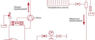
Static pressure in the heating system and its calculation.
The operating pressure in the heating system is the most important parameter, on which the operation of the entire network depends. Deviation in any direction from the values provided for in the project not only reduces the efficiency of the heating circuit, but also significantly affects the performance of the equipment, and in some cases, sometimes even damages the equipment. Please note that certain differences in the heating system are determined by the principle of the device, and this lies in the difference in pressure in the return and supply pipelines. If there are spikes that are greater than this value, immediate action should be taken.
Test pressure
Residents of apartment buildings know how utility services, together with specialists from energy companies, check the coolant pressure in the heating system. Usually, before the start of the heating season, they supply coolant into the pipes and radiators under pressure, the value of which approaches critical levels.
Pressure is used when testing a heating system in order to test the performance of all elements of the heat supply structure under extreme conditions and find out how efficiently heat will be transferred from the boiler room to a multi-story building.
When test pressure is applied to the heating system, its elements often fall into disrepair and require repairs, as worn-out pipes begin to leak and holes form in the radiators. Timely replacement of outdated heating equipment in the apartment will help to avoid such troubles.
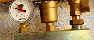
When conducting tests, parameters are monitored using special instruments installed at the lowest (usually the basement) and highest (attic) points of the high-rise building. All measurements taken are subsequently analyzed by specialists. If there are deviations, it is necessary to detect problems and correct them immediately.
General information
Questions about the term
Network pressure can be divided into two main components:
- Static pressure in the heating system. This component will depend on the height of the water column or any other coolant that is in the container and pipes. This pressure exists even if everything is at rest.
- Dynamic pressure. It represents a special force that can act on the internal surfaces of a system when water or other medium moves.
There is also a separate concept as maximum working pressure. This is the maximum permissible value, and if it is exceeded, it will be fraught with the destruction of some network elements.
What pressure in the heating system can be considered optimal?
During the design of a heating system, the water (coolant) pressure inside the system is calculated based on the number of floors of the building, the total length of the pipes and the total number of radiators. As a rule, for cottages and private houses, the optimal readings of the medium pressure in the heating circuit are located in the range of 1.5-2 atm.
For houses with many apartments and their height limited to five floors, as well as those connected to a central heating system, the network pressure ranges from 2 to 4 atm. For houses with 9-10 floors, the normal pressure is from 5 to 7 atm, and for buildings that are higher than 10 floors, the norm is a pressure from 7 to 10 atm.
Security measures
Since when designing autonomous heating systems, a small margin of safety is built in to save money, but even a small pressure surge of up to 3 atm can lead to depressurization of individual elements or their connections.
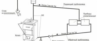
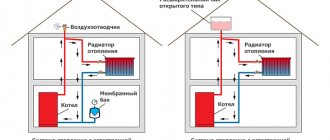
In order to smooth out pressure drops due to instability of the pump or changes in the temperature of the coolant, an expansion tank should be installed in a closed heating system. Unlike a similar device that is used in an open system, in this case there is no communication with the atmosphere. One or even several walls are made of elastic material, due to which the tank plays the role of a damper during water hammer or pressure surges. The fact that an expansion tank is installed cannot always guarantee that the optimal pressure is maintained.
In certain cases it may even exceed the maximum permissible values:
- If you select the wrong container as an expansion tank.
- During malfunctions of the circulation pump.
- When the coolant overheats, and this happens due to a malfunction of the automatic boiler box.
- Due to incomplete opening of the locking valve after maintenance or repair work.
- Due to the formation of an air lock (this can provoke an increase in pressure, or maybe a drop).
- When the throughput of the dirt filter decreases due to contamination.
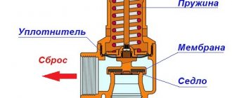
For this reason, in order to avoid emergency situations when creating closed-type heating systems, it is imperative to install a safety valve that will discharge excess coolant when the permissible pressure value is exceeded.