Operating principle of recharge
Operating principle of recharge
Makeup is needed to restore volume or pressure in the heating system. When the device adds working fluid, it automatically stops after the main indicators are equalized. Most often, the equipment is connected to a cold water supply, and liquids are drawn from there. Another option is a storage tank, where you have to manually replenish the supply, and it is usually intended for synthetic products.
Two types of heating make-up have been developed:
- Manual. Designed for small closed circuits where small pressure surges occur. A pressure gauge is used to detect leaks in a timely manner. When the pressure drops, by opening the corresponding tap, water is supplied, thereby replenishing the losses. The liquid flows between the pipes either independently or using a special pump. Budget solutions have an overflow pipe in the expansion tank; when the water reaches this mark, the liquid supply is stopped. The only disadvantage of such a device is the need for constant supervision and experience in performing the procedure.
- Automatic. The equipment independently processes data from the pressure gauge. When a critical point is reached, the working fluid supply valve opens. As with manual control, the pressure in the cold water supply is sometimes not enough, so pumps are installed. When water losses in the heating system are restored, the valve closes. The advantage over the manual method is the automation of the process. When you leave home for a few days, you don’t need to worry that the boiler will overheat or break down. The disadvantage is the increase in electricity costs.
The need for recharge does not always arise. To prevent the equipment from being idle, it can be used for other purposes. It is capable of filling the pipeline with water or synthetic coolant. The equipment will come in handy at the beginning of the heating season, when pressure testing of the entire system is carried out. The device is also suitable for flushing pipes, discharging water or filtering it from coarse particles.
Signs of lack of coolant
Water in the heating system circuit can decrease for various reasons. And this happens quite often. If the owners of the house have not yet bothered to install an automatic system for replenishing the heating network, you can determine the lack of coolant by the following signs:
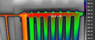
- overheating of the supply water supply and cold radiators;
- gurgling water in the riser;
- frequent starts and stops of the gas boiler burner;
- overheating of the solid fuel boiler and activation of the safety valve.
overheating of the supply water supply and cold radiators;
gurgling water in the riser;
frequent starts and stops of the gas boiler burner;
overheating of the solid fuel boiler and activation of the safety valve.
A shortage of coolant in the circuit is especially dangerous if a TT boiler is used as the main heating equipment in the network. If there is not enough water in such a unit, it will boil. After its complete evaporation, a fire will definitely start in the boiler room. Unfortunately, such situations are far from uncommon.
Also, due to a lack of coolant in the heating system, pipes may melt, radiators may fail, etc. Therefore, it is imperative to monitor the pressure in the circuits of heating systems set for private houses (1.5-2 bar).
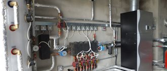
Elements of the make-up device
The recharge scheme for heating networks will depend on the hourly productivity of the standard recharge. For large main heating networks, in which the standard recharge is hundreds and sometimes thousands of cubic meters of water per hour, the complex includes: a water tank, chemical water treatment, automation, electric pump and shut-off and control valves. When performance decreases, the number of circuit elements can be significantly changed.
System recharge unit
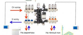
Boiler gearbox
The reducer is installed on the return pipeline in front of the boiler to supply make-up water to the network circuit. Water from the city water supply flows through the valve when the pressure in the network pipeline drops due to leaks or release of an air lock. If the diagram provides for the installation of a circulation pump, then it is installed second. Otherwise, the operation of the entire heating system may be disrupted.
The gearbox operates automatically without maintenance personnel. Sometimes this is not always convenient, since it is impossible to control the leak, and its size can reach emergency proportions. Therefore, many users prefer manual recharge mode or install systems with alarms for high leakage levels.
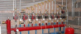
Pump group
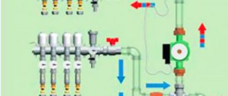
One or more pumps supply make-up water in front of the boiler units at a pressure higher than that in the return network water. The pump is activated by a pressure sensor and supplies water from the make-up water tank.
There are schemes with a submersible pump that can take water from a well or well. The pump group is calculated based on the hourly productivity of the standard make-up; the number of electric pumps must be at least 2, one of which is a reserve one.
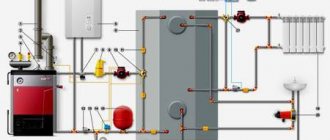
Diagram of a heating system with make-up
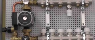
Actuating mechanism
It is installed to control the valve on the make-up line. Usually it is included in the make-up unit, consisting of a shut-off and check valve. It has electrical contacts for sending a signal to control the pump. The mechanism is adjusted to the permissible operating pressure. The actuator is usually a valve with an electric motor.
When the pressure in the return drops below the permitted value by 10%, the electric motor begins to rotate, opening the make-up valve, water from the water tank or from the municipal water supply with a pressure higher than in the return flows into the internal heating circuit.
As it is filled, the pressure reaches the operating value, the sensor gives a signal to close the valve, the electric motor of which begins to rotate in the opposite direction.
Make-up - heating network
Feeding heating networks with a mixture of boiler blowdown water and water softened using the sedimentation method (without phosphate softening) is not allowed due to the risk of silting of the heating network with the products of the additional softening reaction.
The heating network is fed with softened, deaerated water, the quality of which meets the quality requirements for network and make-up water for hot water boilers, depending on the type of heat source and heat supply system.
Heating networks must be fed continuously using booster pumps or directly from feeder tanks. The number of make-up pumps must be at least two, one of them is a reserve one.
The heating network must be fed continuously in order to maintain a given pressure on the suction side of the network pumps during the operating mode of the heating networks and when the network pumps are stopped.
Replenishment of heating networks, therefore, is the process of replenishing losses or disassembling water from heat pipelines or heat consumer systems.
Blowdown water from steam boilers and steam converters is often used to feed heating networks. In cases where the above-mentioned purge lines are directly connected to the return line of the heating installation, they are usually equipped with check valves.
To feed heating networks, as well as evaporators and steam converters, it is allowed to use part of the washing water of anion exchange filters, as well as H - cationized water after the breakthrough of N3 prl, provided that it is decarbonized and neutralized.
To feed heating networks, as well as evaporators and steam converters, it is allowed to use part of the washing water of anion exchange filters, as well as H - cationized water after breakthrough Ma, provided that it is decarbonized and neutralized.
To feed heating networks, deaerated water (natural or softened by soda-lime, cation exchange or other method) or water with stabilized hardness should be used.
It is allowed to replenish the heating network with boiler blowdown water or a mixture of it with cationized water. To protect the heating network from corrosion, the make-up water must be alkaline and must be sulfated (chapter). To save the reagent (sodium sulfite), the heated water should be sulfated.
Water for feeding heating networks with open water supply must have a carbonate hardness of no more than 700 mcg-eq/kg, and must also meet sanitary standards for drinking water. To obtain water of the specified quality, tap water is used, treated according to the following scheme: H - cationization in the starvation mode of cation exchanger regeneration - buffer cationization - decarbonization. The introduction of buffer cationization into the scheme serves to smooth out fluctuations in alkalinity and eliminate acidity if it appears in the filtrate after H - cation exchange filters.
The installation for replenishing heating networks must ensure their replenishment with chemically purified deaerated water in operating mode and emergency replenishment with untreated water from domestic or industrial water supply systems.
Water for feeding heating networks must meet the following requirements: residual hardness 0 8, oxygen content 0 1 mg/l; There should be no sludge in the make-up water.
Water for feeding heating networks with direct water supply must also meet sanitary standards for drinking water.
The installation for replenishing heating networks must ensure their replenishment with chemically purified deaerated water in operating mode and emergency replenishment.
Manual recharge scheme
The simplest option for filling the system is implemented in 90% of double-circuit wall-mounted boilers, where a cold water supply pipe is a priori connected. A manual valve is installed inside the housing, connecting this line with the heating return line. Often, a boiler feed tap is found on solid fuel heat generators with and without a water circuit (for example, heating units of the Czech brand Viadrus).
Reference. On some models of gas heaters equipped with a DHW heat exchanger (in particular, Beretta), instead of a manual tap, manufacturers install an automatic make-up valve with an electromagnetic drive. If the coolant pressure drops below 0.8 Bar, the boiler itself draws water to the required level.
In wall-mounted double-circuit heat generators, the make-up valve is located at the bottom, where the pipelines are connected
. To assemble a classic make-up unit suitable for any type of system, you will need the following parts:
- tee with side outlet DN 15-20, corresponding to the material of the heating main pipe - fitting for metal-plastic, polypropylene, and so on;
- poppet (spring) check valve;
- ball valve;
- couplings, fittings.
The purpose of the check valve is to prevent water from the heating network from flowing back into the water supply system. If we are talking about pumping antifreeze using a pump, you cannot do without a valve. The fittings are installed in the order listed:
- The tee cuts into the heating return after the circulation pump.
- A check valve is connected to the outlet pipe of the tee.
- Next is a ball valve.
Advice. If there is no fine filter at the entrance of the water supply to a private house, it is advisable to provide one on the make-up line. The element will protect the heating system from the entry of fine sand and rust particles that accumulate on the check valve plate and in the seats of three-way valves.
The operating principle of the unit is simple: when the tap is opened, water from the centralized main flows into the heating pipelines, since its pressure is higher (4-8 Bar versus 0.8-2 Bar). The filling process of a closed system is monitored by a boiler or safety group pressure gauge. If you accidentally exceed the pressure, use the Mayevsky tap on the nearest radiator and bleed off excess water.
To control the amount of coolant in the expansion tank of an open heating network located in the attic of the house, the tank must be equipped with 2 additional tubes with a diameter of ½ inch:
- The control line, ending with a tap in the boiler room, cuts into the side wall at approximately half the height of the tank. By opening this valve, you can determine the presence of water in the tank without climbing into the attic.
During the replenishment process, air bubbles escape through the tank lid, the maximum level is monitored by the flow of water from the upper fitting through the pipe - The overflow tube is inserted 10 cm below the tank lid, the end is discharged into the sewer or simply onto the street under the roof overhang. Being in the furnace room and opening the feed tap, you should see this pipe; when water flows from there, filling stops.
Comment. If you are interested in calculating the minimum volume of the expansion tank, follow the dedicated link.
The circuit with a check valve and shut-off valve is also applicable for filling solar systems (solar collectors) and geothermal circuits of heat pumps with antifreeze. How to use the boiler make-up valve is described in the video:
Operating principle and types of node control
The main task of the make-up device is to add the missing coolant to the heating system so that the operating pressure returns to normal. When the required value of this parameter is reached, the feeding flow is interrupted. In the vast majority of cases, the equipment is connected to a cold water supply, but it is also possible to recharge from a storage tank.
In addition to the convenient automatic one, the recharge unit can also have mechanical control. Mechanically controlled make-up is convenient where the system is small, and pressure surges are regulated using expansion tanks. The loss of a small volume of water here can be compensated for independently by monitoring the pressure gauge and manually opening the corresponding tap. The liquid can be supplied either by gravity or using a make-up pump. In typical gravity installations, coolant is supplied until it comes out of an overflow pipe welded to the tank.
The key disadvantage of manual recharge control is the need to have experience in performing such manipulations and to have certain knowledge and skills.
Expansion tank diagram
Automatic make-up valves are more relevant for large branched systems. Very often they are already “included” in the boiler package, being part of its automation.
Installation of such a device makes the operation of the heating system convenient and safe. The huge advantage of automatic recharge, like any other self-regulating installation, is that there is no need for human intervention. Apart from occasional preventive checks, it does not require any additional monitoring.
Installation of an automatic recharging unit can be carried out in both horizontal and vertical positions
It is worth noting that the make-up unit is used not only to add liquid to the heating system - it is multifunctional. It is used to carry out: initial filling of the heating system with water or antifreeze, complete draining of the coolant, water preparation, pressure testing and flushing of the system.
All elements of the automatic make-up valve for the heating system must be made of high-quality materials: stainless steel, brass, high-strength plastic
Automatic make-up unit
If you are firmly confident in the reliability and quality of the system, you can install an automated circuit that adds water from the cold water pipe. What you need to buy:
- pressure reducing valve (simpler - reducer);
- 3 ball valves;
- 2 tees;
- pipe for the bypass device.
Important point. The water entering the reducer must be pre-cleaned with a coarse strainer, otherwise the valve will quickly become clogged. If such a filter is not provided at the entrance to the building, install it in front of the make-up unit.
In this diagram, the pressure gauge shows the pressure on the side of the heating network; bypass and taps are needed to service the recharge module
The main executive element of the circuit - the gearbox - consists of the following parts:
- fine filter on the inlet pipe;
- spring seat valve with rubber seals;
- pressure regulator handle with a printed scale, range – 0.5…4 Bar (or higher);
- manual shut-off valve;
- check valve at the outlet.
Note. There are more expensive models of make-up reducers with a built-in pressure gauge that measures the pressure on the side of the heating system. Since this device is already in the safety group or boiler, there is no point in spending extra money and duplicating it. The exception is the situation when the make-up is installed far from the heat source (read the next section).
As you can see, the pressure reduction machine already contains all the necessary elements - a filter, a check valve and a regulator. All that remains is to assemble a simple circuit with a bypass and service taps designed for removing and servicing the gearbox.
Operating the valve is simple - use the regulator to set the minimum pressure threshold in the heating network, open the direct line taps, and close the bypass.
Advice. If you plan to install a coarse filter in front of the gearbox, provide an additional service tap in order to clean the mesh without turning off the water in the entire house.
To organize the automatic addition of antifreeze to the system, you can adapt a “hydrofor” - a water station with an electric pump designed for water supply from a well. The pressure switch of the unit must be reconfigured to a minimum pressure of 0.8 Bar, a maximum pressure of 1.2...1.5 Bar, and the suction pipe must be directed into a barrel with non-freezing coolant.
The appropriateness of this approach is highly questionable:
- If the “hydrofor” works and starts pumping up antifreeze, you will still have to look for and eliminate the cause of the problem.
- If the owners are absent for a long time, replenishment will also not save the situation in the event of an accident, since the size of the container is limited. The pumping station will extend the heating operation for some time, but then the boiler will turn off.
- Placing a large barrel is dangerous - you could flood half the house with toxic ethylene glycol. Non-toxic propylene glycol is too expensive, as is spill cleanup.
Examples of organizing automatic refueling from containers of different capacities
. Conclusion. Instead of additional pumps and automatic gearboxes, it is better to purchase an electronic unit of the Xital type. After a relatively inexpensive installation, you will be able to control the heating operation via a cell phone or computer and quickly respond to emergency situations.
Automatic make-up of the heating system - diagram of the unit and make-up valve
When air vents in a heating system are activated due to air escaping, the volume of coolant certainly decreases. Also, the number of liters of coolant becomes smaller due to the cleaning of filters from various contaminants. In addition, changes in temperature conditions, which depend on the weather outside the window, result in an increase or decrease in heat loss from the building. As a result, the operating mode of the heating unit’s burner periodically changes. This element of the boiler either intensively heats the water or operates in economical mode.
The cyclical operation of the heating system often leads to sudden changes in pressure in different components of the structure and the activation of safety valves. As a result, the collet connections may become loose and the coolant will begin to leak out.
In order to prevent emergency situations in the heating system, it is necessary to maintain a constant volume of coolant liquid and pressure in accordance with the recommendations of the boiler manufacturers (according to the technical data sheet). This can be done by an automatic replenishment unit for the heating system.
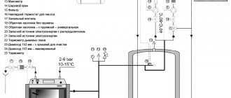
The main part in it is the pressure reducing valve shown in the photo.
The heating system make-up valve is equipped with a special membrane under coolant pressure. Thanks to the tension of the spring, the required pressure for the liquid is established, at which the membrane moves to the upper position and ultimately compresses the spring. The use of a valve makes recharging a closed heating system faster, easier and safer. After the pressure in the heating system drops (behind the valve), the coolant no longer acts on the membrane, and the spring pushes the valve stem down, opening a gap in the seat in this element. Water from the plumbing structure begins to flow through the opened hole into the pipeline of the heating system. After reaching the nominal pressure, the membrane bends upward and closes the valve seat.
It should be noted that the pressure relief valve for automatically recharging the heating system is often open. It responds to every operation of automatic air vents. Since air is removed from the heating structure on a regular basis, the automatic replenishment of the heating system operates quite often.
To prevent dirty water from entering the water supply system, a check valve is installed behind the pressure reducing valve. This element is either built into the pressure reducing valve body or used as a separate part.
Modern environmental requirements stipulate that a flow breaker or check valve should also be located in front of the pressure reducing valve.
A part such as a flow breaker performs the function of a check valve, but is an improved product consisting of two check valves and a drain pipe located between them. According to European regulations, a flow breaker must be installed. The fact is that hot water entering the water supply network from the heating structure provokes the proliferation of various bacteria in the pipes, settling on the inner surfaces of the walls.
In order to soften the water and prevent the appearance of scale, as provided for in the heating system recharge scheme, a water treatment filter is installed in front of the pressure reducing valve.
Sometimes it is replaced with ordinary mesh filters or mud filters. Mesh filters that do not have a transparent flask can be equipped with pressure gauges, which allows you to monitor the pressure of the coolant in front of them and behind these products (read: “Filter for a heating system - principle of operation and installation”). According to the pressure drop indicators, the degree of filter contamination is determined.
It is recommended to bypass the heating system make-up unit using a bypass and shut-off (ball) valves. If suddenly this unit or one of its elements fails, then replenishment is carried out through a bypass (for more details: “What is a bypass in a heating system and why is it needed - types, installation rules”). The most convenient place to connect such a unit is the point where the expansion tank is located, which serves as a “zero” reference point in the design.
The fact is that in this place the heating system is fed - the calculation confirms this - the pressure reducing valve functions most accurately. But in this case, a problem arises because this location of the make-up unit is too close to the heating boiler.
As a result, water from the water supply mixes with the return water, cools the liquid and it enters the unit too cold, which adversely affects the operation of the device.
For this reason, if the replenishment of the heating system of a private house should be located close to the heating unit, it is recommended to install the unit in the hot water supply system. If the water supply in a country house is irregular, a storage hydraulic accumulator is installed in front of the recharge unit, which comes in two types. This is either a feeding tank for the heating system in the attic, or a membrane tank similar to an expansion tank. When the water pressure in the water supply is less than in the heating system, the pressure reducing valve will not function, then it is necessary to install a hydraulic accumulator.
The heating make-up unit is connected directly to the household water supply battery.
How to connect to the heating system
With a closed circuit, there is not much difference where to connect the make-up pipeline - to the supply or return. We recommend using the classic proven method - the insertion point should be located on the return line next to the boiler, after the circulation pump and expansion tank. Causes:
- the unit is located in the combustion room, next to the equipment and instruments;
- pumping water into the return line is immediately reflected on the pressure gauge installed in the supply behind the boiler;
- the insert is located at the lowest point, the flow is distributed in 2 directions - into the boiler and radiators, the air is squeezed out evenly.
Classic scheme for inserting a recharge module
The piping of solid fuel units involves the installation of a condensation protection circuit with a three-way valve. You cannot make makeup in front of this valve - cold water will immediately close it and the boiler pressure gauge will begin to lag in readings. Cut inside the circuit, between the 3-way valve and the heat generator.
In a similar way, the make-up flows into the return line of the open system. The second option is to add coolant directly to the tank; the disadvantage of this method is to lay the supply pipe into the attic.
How to arrange a heating system make-up
The key function of the make-up unit is to compensate for the lack of coolant in the circuit. Liquid is added to the system until the operating pressure level reaches the required values. It is most convenient to feed the circuit with water through a cold water supply pipe connected to the unit. If antifreeze (non-freezing liquid) is used for heating, connect a container.
To replenish the coolant volume, one of two modes is used:
- Manual (suitable for small-volume autonomous systems). The user is required to regularly check the pressure gauge readings and, if the pressure drops, open the valves of the make-up unit. Water enters the circuit by gravity or is supplied under pressure using a pump to recharge the system. If the heating installation is gravity-based, the valve of the make-up unit is closed after waiting for a trickle of water from the overflow pipe connected to the open expansion tank.
- Auto. When the pressure in the circuit drops below operating values, the valve of the make-up unit opens (or a valve equipped with an electric drive), and coolant, pumped by a special pump, enters the system through the flow hole. After the pressure normalizes, the pump turns off and the valve closes. The make-up device may be part of the heating boiler. The advantage of automatically recharging the heating system is that there is no need to systematically check the pressure gauge readings and maintain the system. The disadvantage is the addition of volatile elements.
It is most convenient to recharge an open system not through a special unit on the return pipe, but through an expansion tank located at the top point of the circuit. In order not to go upstairs every time to assess the coolant level in the tank, three pipelines in addition to the supply one are welded to the tank.
Open expansion tank diagram
Part of the heating circuit is the supply and return pipes (indicated in the diagram). To check the liquid level in the tank, simply open the tap on the control pipe connected to the sewer drain in the boiler room. If the water flows, the level is sufficient. In the opposite situation, turn on the make-up valve from the water supply and monitor the overflow pipe - when water comes out of it, the supply tap can be turned off.
Note! If the boiler heat exchanger is made of cast iron, it is recommended to install just such a make-up circuit for an open system. Otherwise, the cast iron may crack if cooled coolant enters from the return pipe or the boiler feed unit. When feeding through the return unit, the valve should be opened only a third so that cold water is added little by little.
In a closed system, an automated unit can be provided, but its arrangement requires the use of additional fittings. Let's consider the functions of each of the elements of the unit, with the help of which the heating system is automatically recharged.
Elements of a make-up unit in a closed system
Actuating mechanism
To energize the home heating circuit manually, it is enough to install one mechanical valve that shuts off the supply of water from a cold pipeline or antifreeze from a tank. Automatic make-up requires the installation of fittings that are controlled remotely - this can be a valve or an electric tap, but most often an automatic make-up pressure reducing valve is used (it is indicated in the diagram above).
The make-up reducer is a combined device consisting of a pressure reducer, check valve and shut-off valve. The make-up valve can be mechanical or equipped with terminals for connection to an electric pump.
Make-up valve in the heating system
The principle of operation is as follows: the regulator is adjusted - the maximum and minimum permissible levels of operating pressure of the coolant are set. When it drops to the lower threshold, the valve membrane is activated, opening the flow hole. When the upper pressure level is reached, the replenishment stops, as the membrane presses on the spring, as a result of which the flow is blocked by the rod.
The pressure reducing valve for the heating system is adjusted using a screw in the upper part. A pressure gauge is provided on the valve or make-up tap, which allows you to visually monitor the pressure during adjustment.
Check valve
It is important that the heated coolant does not penetrate the pipeline through which cold water is supplied. This threatens the entry of cold water into the system and the proliferation of bacteria, including pathogens. In addition, the coolant circulating along the circuit of the autonomous heating network accumulates corrosion products and harmful substances released from various materials under heating. Their presence in drinking water is harmful to health.
Check valve with plastic core
In addition, installing a check valve in the make-up system avoids unnecessary loss of coolant. When replenishing, the reverse movement of liquid from the heating circuit occurs due to insufficient pressure in the supply pipe. Moreover, in the water supply system the pressure is, by definition, lower than in the heating circuit. Reverse movement of the coolant can also be observed during operation of the heating system if the closing valve does not ensure a hermetically sealed shutoff of the outlet.
The check valve can be built into the reducer to feed the heating system, or it can be installed behind the actuator. For reliability, today they install a check valve in front of the actuator, or use a flow breaker.
Pump and storage tank
A make-up pump is necessary to create pressure, due to which the heating circuit will be replenished with water from the water supply, which has a lower pressure. In order for the closed heating system to be automatically recharged, the pump receives a signal to turn on, which is given to it by an electromagnetic actuator.
Pump and storage tank
Attention! The recharge system design may involve the direct use of a vertical pump installed in a well or well. Or pumping equipment pumps water into a special reservoir, which is connected to the feeding system - in this case, the lost volume of coolant will be replenished regardless of the pressure level in the cold water supply. In a gravity system, the refill tank is placed above the expansion tank; in an automatic system, a membrane accumulator is used - it will always be under pressure.
Coolant filtration
Tap water often contains mechanical inclusions, and these impurities can damage the devices that ensure the functioning of the heating system. Therefore, a mesh dirt filter is installed at the entrance to the unit. It traps mechanical contaminants. Shut-off valves are installed before and after the filter so that, if necessary, you can clean or change the filter without hassle. In addition to the mesh filter, a softener can be used - it will remove calcium salts and other substances from the incoming coolant that can settle as an insoluble sediment in heating radiators.
Filtration water purification system
Make-up connection
It is recommended to place the automatic replenishment unit in an area with minimal pressure - that is, on a straight section of the return pipe, preferably at the lowest point. It is important that there is some distance between the feeding system and the heating boiler - this will avoid contact of the cold coolant with the hot heat exchanger of the boiler.
The diagram of the automated recharge unit provides for its piping using a bypass - bypass with shut-off valves will allow you to repair or adjust the unit without turning off the heating system.
Automatic water heating make-up system
Finally, about the safe addition of coolant
When filling water or partial replenishment, follow our recommendations:
- Replenish the heated system slowly by opening the valve a quarter of the lever stroke. In this way, it will be possible to avoid the formation of air locks and protect the boiler heat exchanger from temperature shock.
- Refill from scratch with the heat generator not working and the circulation pump turned off.
- Check the pressure in the expansion tank and go through all the radiators, opening the Mayevsky valves to release air.
- If your boiler is equipped with modern electronics, be sure to study the instructions regarding make-up. Often it is necessary to activate a special service mode in the unit.
- Excess pressure is easily released through the nearest air vent.
The complex system make-up module can be connected to a hydraulic separator and a comb
Reference. Cast iron heat exchangers easily crack from sudden temperature changes, and steel fireboxes become covered from the inside with condensation. The latter mixes with soot and forms a dense coating.
Injecting antifreeze with a hand pump does not have any pitfalls. Pressure testing units are equipped with their own pressure gauge, which allows you to monitor the current pressure at the insertion point.
Simple ways to recharge
The easiest way to replenish your water supply is to do it manually. To implement it, you need to lay a section of pipeline connecting the return line of the heating system to the centralized water supply. In this area you need to install a shut-off valve and a filter device. A simple recharge scheme is shown in the figure:
This scheme is suitable for any simple heating systems for small private houses. The supply pipeline is connected to the return line in front of the pump, since this section has the lowest pressure and temperature of the coolant. But along with its simplicity, this method also has a lot of disadvantages:
- The homeowner will have to constantly monitor the amount of water in the pipes by looking into the open expansion tank or monitoring the pressure gauge of a closed heating system;
- The volume of replenishment of the heating system must also be adjusted independently until water flows through the overflow pipe of the expansion tank.
Advice. To prevent the coolant from accidentally escaping into the water supply pipe when there is no pressure in it, install a spring check valve in front of the shut-off make-up tap.
The correct solution for open systems would be to add water not to the return line, but directly to the expansion tank. Then you won’t have to constantly climb into the attic or under the ceiling to assess the coolant level. The solution is implemented by welding 3 additional pipelines to the tank, as shown in the diagram:
It is assumed that one supply pipe is already welded to the container. The recharge unit shown in the diagram works as follows: coolant circulates through the supply and return pipes, its level in the tank is checked by opening the tap on the control pipe. It is lowered into the boiler room to the nearest sewer drain. If water flows after opening the tap, then the level in the container is normal. If the result is negative, the control valve is closed and the make-up valve is turned on. Filling occurs until the coolant flows through the overflow. Although here you also need to do everything yourself, cold water does not flow directly into the boiler.
Important. Often boilers, especially solid fuel ones, have a cast iron heat exchanger, which can crack due to temperature changes. Therefore, during replenishment, especially according to the first scheme, open the tap no more than a third so that cold water flows slowly.
Installation features
The direction of the water must coincide with the direction of the arrow on the body of the device.
The valve is placed on the pipe so that the direction of the liquid coincides with the direction of the arrow. The filter plug is directed downward, and the adjustment screw must be accessible for use. The pressure gauge dial rotates to make it easy to read the values.
The winding material is used rationally so that excess does not fall into the lumen of the gearbox. Boiler feed in the form of a valve should not depend on main loads (compression, torsion, bending, vibration). For this purpose, additional supports or compensators are installed.
The mismatch between the axes of the pipelines should not be more than 3 mm for a length of 1 m. For longer lengths, 1 mm is added for each linear meter. The make-up circuit is connected to the pipeline near the expansion tank.
Recharge calculation
The calculation of the required volume of added water is carried out in accordance with SNiP 41-02-2003 “Heating networks”.
In closed heating circuits, a coefficient of 0.075 is used to the total volume of energy in the networks and pipelines connected to them.
A multiplier of 0.05 is applied to the volume to calculate the make-up of areas that are more than 5 km from the boiler house, in open and closed systems.
In open pipelines, a coefficient of 0.12 is taken to the average liquid flow rate for hot water supply and the actual volume of energy carrier in the pipes is added with a multiplier of 0.075.
LitLife
Valentin Krasnik
Rules for the technical operation of thermal power plants in questions and answers: A guide for studying and preparing for the knowledge test
1. GENERAL PROVISIONS
Question 1.
What requirements do these Rules establish?
Answer.
Establishes requirements for the technical operation of the following thermal power plants:
industrial, industrial heating and heating boiler houses with an absolute steam pressure of no more than 4.0 MPa and with a water temperature of no more than 200 °C using all types of organic fuel, as well as using non-traditional renewable energy resources;
steam and water heating networks for all purposes, including pumping stations, condensate collection and return systems and other network structures;
heat consumption systems for all purposes (technological, heating, ventilation, hot water supply, air conditioning), heat-consuming units, consumer heating networks, heating points, and other structures of similar purpose (clause 1.1).[1]
Question 2.
Which thermal power plants are not covered by these Rules?
Answer.
Does not apply to thermal power plants:
thermal power plants;
sea and river vessels and floating facilities;
rolling stock of railway and road transport (clause 1.2).
Question 3.
What kind of accounting of thermal power plants is kept in the organizations that operate them?
Answer.
Records are kept in accordance with Appendix 1.
Question 4.
Which bodies supervise compliance with the requirements of these Rules, the rational and efficient use of fuel and energy resources in organizations, regardless of their form of ownership and departmental affiliation?
Answer. Carried out by state energy supervision bodies (clause 1.6).
Question 5.
Who is responsible for compliance with these Rules?
Answer.
Bears the head of the organization that is the owner of thermal power plants, or the technical manager who is entrusted with operational responsibility for thermal power plants, in accordance with the legislation of the Russian Federation (clause 1.7).
2. ORGANIZATION OF OPERATION OF THERMAL POWER INSTALLATIONS
2.1. General provisions
Question 6.
What document appoints the person responsible for the good condition and safe operation of thermal power plants and his deputy?
Answer.
Appointed by an administrative document of the head of the organization from among the management personnel and specialists of the organization (clause 2.1.2).
Question 7.
What document establishes the boundaries of responsibility of production departments for the operation of thermal power plants?
Answer. They are established by the administrative document of the head of the organization. The manager determines the responsibility of officials of structural divisions and services, based on the structure of production, transportation, distribution and consumption of thermal energy and coolant, providing for the specified responsibility in the official duties of employees and assigning it by order or regulation (clause 2.1.3).
Question 8.
Who is personally responsible for failure to comply with these Rules, which causes disruptions in the operation of a thermal power plant or heating network, a fire or an accident?
Answer. Personal responsibility is borne by:
workers directly servicing and repairing thermal power plants - for each violation that occurred through their fault, as well as for incorrect actions when eliminating violations in the operation of thermal power plants in the area they service;
operational and operational-repair personnel, dispatchers - for violations committed by them or personnel directly subordinate to them performing work on their instructions (order);
management personnel and specialists of workshops and departments of the organization, heating boiler houses and repair enterprises; chiefs, their deputies, foremen and engineers of local production services, sites and mechanical repair services; chiefs, their deputies, foremen and engineers of heating network districts - for unsatisfactory organization of work and violations committed by them or their subordinates;
heads of the organization operating thermal power plants and their deputies - for violations that occurred at the enterprises they manage, as well as as a result of unsatisfactory organization of repairs and failure to implement organizational and technical preventive measures;
managers, as well as specialists of design, engineering, repair, commissioning, research and installation organizations that carried out work on thermal power plants, for violations committed by them or their subordinate personnel (clause 2.1.4).
Question 9.
What document determines the division of responsibility for the operation of thermal power plants between an organization that is a consumer of thermal energy and an energy supplying organization?
Answer. Determined by the energy supply agreement concluded between them (clause 2.1.5).
2.2. Personnel tasks
Question 10.
What does the head of the organization provide? Answer. Provides:
maintenance of thermal power plants in working order and their operation in accordance with the requirements of these Rules, safety and labor protection requirements, compliance with industrial and fire safety during the operation of equipment and structures, as well as in accordance with other regulatory and technical documents;
timely and high-quality implementation of preventive work;
repair, modernization and reconstruction of thermal power plants;
development of job and operational instructions for personnel;
personnel training and knowledge testing of operating rules, safety precautions, job and operational instructions;
maintaining good condition, economical and safe operation of thermal power plants;
compliance with the requirements of regulatory legal acts and regulatory and technical documents regulating the relationship between producers and consumers of thermal energy and coolant;
preventing the use of technologies and work practices that have a negative impact on people and the environment;
recording and analysis of disturbances in the operation of thermal power plants, accidents and taking measures to prevent accidents and injuries;
unhindered access to power installations by representatives of state supervisory authorities in order to check their technical condition, safe operation and rational use of energy resources;
compliance with the instructions of state supervisory authorities within the established time frame (clause 2.2.1).
Question 11.
Whom does the head of the organization appoint to directly implement sanctions for the operation of thermal power plants?
Answer. Appoints a person responsible for the good condition and safe operation of the organization's thermal power plants and his deputy from among the management personnel or specialists with special heat and power education after checking the knowledge of these Rules, safety regulations and instructions (clause 2.2.2).
Question 12.
Who can be held responsible for the good condition and safe operation of thermal power plants when consuming thermal energy only for heating, ventilation and hot water supply?
Answer. It can be assigned to an employee from among management personnel and specialists who does not have a special heat and power education, but has undergone training and knowledge testing in the manner established by these Rules (clause 2.2.3).
Current advice on configuration and maintenance
Whatever power supply you choose, remember, first of all, it should be safe and easy to use, made of high-quality materials. If the heating system is small, give preference to a device with the simplest possible design. The central support with moving parts and the internal compensation piston must be made of materials with a low adhesion coefficient: the risk of lime formation in the unit must be minimized. It is no secret that they are the main reason for the poor performance of the device.
Please note whether the product has a replaceable cartridge: this will greatly facilitate and speed up the process of inspecting the unit for you.
Periodic maintenance of the make-up device will help avoid malfunctions in the entire heating system.
To clean or replace the entire cartridge, proceed as follows:
- Insulate the installation.
- Unscrew the control knob located at the bottom.
- Unscrew the adjustment screw until it stops and remove the cover.
- Remove the cartridge with pliers.
- After the necessary manipulations, reassemble the device.
All that remains is to set up the equipment again and continue to enjoy the uninterrupted operation of the heating system in your home!
Make-up in an open heating system
In heating networks of private houses with forced coolant flow, therefore, valves are used for make-up, supplying water to the circuit automatically. In open systems of small residential buildings or dachas, a slightly different, much simpler coolant addition scheme is usually used. Automatic recharging of the heating system in this case will most likely be superfluous.
Expansion tanks in networks with natural coolant flow are usually mounted in the attic. In order to be able to control the amount of water in the circuit in such systems, in addition to the return and supply, two more pipes are connected to them. One of them is called the control one and cuts into the tank below. The second (overflow pipe) is connected to the expansion tank at the top. Next, the pipes are extended, for example, to the kitchen.
Checking whether there is a sufficient amount of water in the heating system circuit when using such a design is quite simple. If the coolant does not flow from the tap embedded in the control pipe of the tank when it is opened, then there is not enough coolant in the system. In this case, before adding liquid to the circuit, open the tap on the overflow pipe. As soon as the system is filled to the required parameters, water will begin to flow from it.