Recommended air exchange rate standards
When drawing up a building project, calculations are made for each individual section.
In production these are workshops, in residential buildings - apartments, in a private house - floor blocks or separate rooms. Before installing a ventilation system, it is known what the routes and sizes of the main lines are, what geometry the ventilation ducts are needed, and what size pipes are optimal.
Do not be surprised by the overall dimensions of air ducts in catering establishments or other institutions - they are designed to remove large amounts of used air
Calculations related to the movement of air flows inside residential and industrial buildings are considered to be the most complex, so experienced, qualified specialists must deal with them.
The recommended air speed in air ducts is indicated in SNiP - regulatory state documentation, and when designing or commissioning objects they are guided precisely by it.
The table shows the parameters that should be followed when installing a ventilation system. The numbers indicate the speed of movement of air masses at the installation sites of channels and gratings in generally accepted units - m/s
It is believed that indoor air speed should not exceed 0.3 m/s.
Exceptions are temporary technical circumstances (for example, repair work, installation of construction equipment, etc.), during which the parameters can exceed the standards by a maximum of 30%.
In large premises (garages, production workshops, warehouses, hangars), instead of one ventilation system there are often two.
The load is divided in half, therefore, the air speed is selected so that it provides 50% of the total calculated volume of air movement (removal of contaminated air or supply of clean air).
If force majeure occurs, there is a need for a sharp change in air speed or a complete suspension of the ventilation system.
For example, according to fire safety requirements, the speed of air movement is reduced to a minimum in order to prevent the spread of fire and smoke into adjacent rooms during a fire.
For this purpose, cut-off valves and valves are installed in air ducts and transition areas.
Features of gas movement
As mentioned above, three parameters are involved in the calculations carried out when constructing ventilation: the flow rate and speed of air masses, as well as the cross-sectional area of the air ducts. Of these parameters, only one is normalized - this is the cross-sectional area. Apart from residential premises and children's institutions, SNiP does not regulate the permissible air speed in the air duct.
In the reference literature there are recommendations on the movement of gases flowing through ventilation networks. The values are recommended based on the purpose, specific conditions, possible pressure losses and noise levels. The table reflects the recommended data for forced ventilation systems.
For natural ventilation, gas movement is accepted with values of 0.2 - 1 m/s.
Subtleties of choosing an air duct
Knowing the results of aerodynamic calculations, you can correctly select the parameters of the air ducts, or more precisely, the diameter of the round sections and the dimensions of the rectangular sections.
In addition, in parallel, you can select a forced air supply device (fan) and determine the pressure loss during the movement of air through the channel.
Knowing the amount of air flow and the speed of its movement, you can determine what cross-section of air ducts will be required.
To do this, take the formula inverse to the formula for calculating air flow: S = L/3600*V.
Using the result, you can calculate the diameter:
D = 1000*√(4*S/π)
Where:
- D is the diameter of the air duct section;
- S – cross-sectional area of air channels (air ducts), (m²);
- π is the number “pi”, a mathematical constant equal to 3.14;.
The resulting number is compared with factory standards approved by GOST, and the products closest in diameter are selected.
If you need to choose rectangular rather than round air ducts, you should determine the length/width of the products instead of the diameter.
When choosing, they are guided by the approximate cross-section, using the principle a*b ≈ S and size tables provided by manufacturers. We remind you that according to the standards, the ratio of width (b) and length (a) should not exceed 1 to 3.
Air ducts with a rectangular or square cross-section have an ergonomic shape, which allows them to be installed flush against walls. This is used when installing home hoods and masking pipes above suspended ceiling structures or above kitchen cabinets (mezzanines)
Generally accepted standards for rectangular channels: minimum dimensions - 100 mm x 150 mm, maximum - 2000 mm x 2000 mm. Round air ducts are good because they have less resistance and, accordingly, have minimal noise levels.
Recently, convenient, safe and lightweight plastic boxes have been produced specifically for indoor use.
Calculation algorithm
When designing, adjusting or modifying an existing ventilation system, air duct calculations must be performed. This is necessary in order to correctly determine its parameters, taking into account the optimal performance and noise characteristics under current conditions.
When performing calculations, the results of measuring the flow rate and speed of air movement in the air channel are of great importance.
Air flow is the volume of air mass entering the ventilation system per unit of time. As a rule, this indicator is measured in m³/h.
Movement speed is a value that shows how quickly air moves in the ventilation system. This indicator is measured in m/s.
If these two indicators are known, the area of circular and rectangular sections, as well as the pressure required to overcome local resistance or friction, can be calculated.
When drawing up a diagram, you need to choose a viewing angle from the façade of the building, which is located at the bottom of the layout. Ducts are shown as solid thick lines
The most commonly used calculation algorithm is:
- Drawing up an axonometric diagram that lists all the elements.
- Based on this scheme, the length of each channel is calculated.
- Air flow is measured.
- The flow rate and pressure in each section of the system are determined.
- Friction losses are calculated.
- Using the required coefficient, the pressure loss when overcoming local resistance is calculated.
When performing calculations on each section of the air distribution network, different results are obtained. All data must be equalized using diaphragms with the branch of the greatest resistance.
Calculation of cross-sectional area and diameter
Correct calculation of the area of round and rectangular sections is very important. An unsuitable cross-section size will not provide the desired air balance.
A duct that is too large will take up a lot of space and reduce the effective area of the room. If the channel size is too small, drafts will appear as the flow pressure increases.
In order to calculate the required cross-sectional area ( S ) , you need to know the values of flow rate and air speed.
The following formula is used for calculations:
S = L/3600*V,
in this case L is the air flow rate (m³/h), and V is its speed (m/s);
Using the following formula, you can calculate the diameter of the duct ( D ) :
D = 1000*√(4*S/π) , where
S – cross-sectional area (m²);
π – 3,14.
If you plan to install rectangular rather than round air ducts, instead of the diameter, determine the required length/width of the air duct.
All obtained values are compared with GOST standards and products that are closest in diameter or cross-sectional area are selected
When choosing such an air duct, the approximate cross-section is taken into account. The principle is used a*b ≈ S , where a is the length, b is the width, and S is the cross-sectional area.
According to regulations, the ratio of width to length should not be higher than 1:3. You should also use the standard size chart provided by the manufacturer.
The most common sizes of rectangular ducts are: minimum dimensions - 0.1 m x 0.15 m, maximum - 2 m x 2 m. The advantage of round air ducts is that they have less resistance and, accordingly, create less noise during operation.
Calculation of pressure loss due to resistance
As air moves along the line, resistance is created. To overcome it, the fan of the air handling unit creates pressure, which is measured in Pascals (Pa).
Pressure loss can be reduced by increasing the cross-section of the air duct. In this case, approximately the same flow rate in the network can be ensured
In order to select a suitable air handling unit with a fan of the required capacity, it is necessary to calculate the pressure loss to overcome local resistance.
This formula applies:
P=R*L+Ei*V2*Y/2 , where
R – specific pressure loss due to friction in a certain section of the air duct;
L – section length (m);
Еi – total local loss coefficient;
V – air speed (m/s);
Y – air density (kg/m3).
R values are determined according to standards. This indicator can also be calculated.
If the duct cross-section is circular, the friction pressure loss ( R ) is calculated as follows:
R = ( X *D/B) * ( V * V * Y )/2 g , where
X – coefficient. friction resistance;
L – length (m);
D – diameter (m);
V is the air speed (m/s), and Y is its density (kg/m³);
g – 9.8 m/s².
If the cross-section is not round, but rectangular, it is necessary to substitute an alternative diameter into the formula, equal to D = 2AB/(A + B) , where A and B are sides.
What device measures air speed?
All devices of this type are compact and easy to use, although they have their own subtleties.
Instruments for measuring air speed:
- Vane anemometers
- Temperature anemometers
- Ultrasonic anemometers
- Pitot tube anemometers
- Differential pressure gauges
- Balometers
Vane anemometers are one of the simplest devices in design. The flow rate is determined by the rotation speed of the device impeller.
Temperature anemometers have a temperature sensor. When heated, it is placed in the air duct and as it cools, the air flow rate is determined.
Ultrasonic anemometers mainly measure wind speed. They work on the principle of determining the difference in sound frequency at selected control points of the air flow.
Pitot tube anemometers are equipped with a special small diameter tube. It is placed in the middle of the duct, thereby measuring the difference in total and static pressure. These are one of the most popular devices for measuring air in an air duct, but they have the disadvantage of being unable to be used in high dust concentrations.
Differential pressure gauges can measure not only speed, but also air flow. Complete with a pitot tube, this device can measure air flows up to 100 m/s.
Balometers are most effective when measuring air velocity at the outlet of ventilation grilles and diffusers. They have a bell that captures all the air coming out of the ventilation grille, thereby reducing measurement error to a minimum.
Section shapes
According to the cross-sectional shape, pipes for this system are divided into round and rectangular. Round ones are used mainly in large industrial enterprises. Since they require a large area of the room. Rectangular sections are well suited for residential buildings, kindergartens, schools and clinics. In terms of noise level, pipes with a round cross-section are in first place, since they emit a minimum of noise vibrations. Pipes with a rectangular cross-section produce slightly more noise vibrations.
Pipes of both sections are most often made of steel. For pipes with a round cross-section, steel is used that is less hard and elastic; for pipes with a rectangular cross-section, on the contrary, the harder the steel, the stronger the pipe.
In conclusion, I would like to say once again about the attention to the installation of air ducts and the calculations carried out. Remember, the more you do everything correctly, the more desirable the functioning of the system as a whole will be. And, of course, we must not forget about safety. Parts for the system should be selected carefully. You should remember the main rule: cheap does not mean high quality.
Calculation Rules
Noise and vibration are closely related to the speed of air masses in the ventilation duct. After all, the flow that passes through the pipes is capable of creating variable pressure that can exceed normal parameters if the number of turns and bends is greater than the optimal values. When the resistance in the channels is high, the air speed is significantly lower, and the efficiency of the fans is higher.
Many factors influence the vibration threshold, for example, pipe material
Standard noise levels
SNiP specifies certain standards that affect residential, public or industrial premises. All standards are indicated in tables. If the accepted standards are increased, it means that the ventilation system is not designed properly. In addition, exceeding the sound pressure norm is permissible, but only for a short time.
If the maximum permissible values are exceeded, it means that the channel system was created with some shortcomings that must be corrected in the near future. Fan power can also influence vibration levels exceeded. The maximum air speed in the duct should not contribute to an increase in noise.
Principles of assessment
Various materials are used to make ventilation pipes, the most common of which are plastic and metal pipes. The shapes of air ducts have different sections, ranging from round and rectangular to ellipsoidal. SNiP can only indicate the dimensions of exhaust pipes, but cannot in any way standardize the volume of air masses, since the type and purpose of the premises may differ significantly. The prescribed standards are intended for social facilities - schools, preschool institutions, hospitals, etc.
All dimensions are calculated using certain formulas. There are no specific rules for calculating air speed in air ducts, but there are recommended standards for the necessary calculation, which can be seen in SNiPs. All data is used in the form of tables.
You can supplement the given data in this way: if the hood is natural, then the air speed should not exceed 2 m/s and be less than 0.2 m/s, otherwise the air flow in the room will be poorly renewed. If the ventilation is forced, then the maximum permissible value is 8-11 m/s for main air ducts. If this standard is higher, the pressure in the ventilation will be very high, which will lead to unacceptable vibration and noise.
Rules for determining air speed
The speed of air movement is closely related to concepts such as noise level and vibration level in the ventilation system. The air passing through the channels creates a certain noise and pressure, which increases with the number of turns and bends.
The greater the resistance in the pipes, the lower the air speed and the higher the fan performance. Let's consider the norms of associated factors.
No. 1 - sanitary standards for noise levels
The standards specified in SNiP apply to residential (private and apartment buildings), public and industrial premises.
In the table below, you can compare standards for different types of premises, as well as areas adjacent to buildings.
Part of the table from No. 1 SNiP-2-77 from the paragraph “Noise Protection”. The maximum permissible norms related to night time are lower than daytime values, and the norms for adjacent areas are higher than for residential premises
One of the reasons for the increase in accepted standards may be an incorrectly designed air duct system.
Sound pressure levels are presented in another table:
When putting into operation ventilation or other equipment related to ensuring a favorable, healthy microclimate in the room, only short-term excess of the designated noise parameters is allowed
No. 2 - vibration level
The power of the fans is directly related to the level of vibration.
The maximum vibration threshold depends on several factors:
- duct sizes;
- quality of gaskets that reduce vibration levels;
- pipe manufacturing material;
- speed of air flow passing through the channels.
The standards that should be followed when choosing ventilation devices and when making calculations regarding air ducts are presented in the following table:
Maximum permissible values of local vibration. If during inspection the actual values are higher than the norms, it means that the air duct system is designed with technical flaws that need to be corrected, or the fan power is too high
The air speed in shafts and channels should not affect the increase in vibration indicators, as well as the associated parameters of sound vibrations.
No. 3 - air exchange rate
Air purification occurs through the air exchange process, which is divided into natural or forced.
In the first case, it is carried out by opening doors, transoms, vents, windows (and is called aeration) or simply by infiltration through cracks at the joints of walls, doors and windows, in the second - with the help of air conditioners and ventilation equipment.
The air in a room, utility room or workshop must be changed several times an hour in order for the degree of air pollution to be acceptable. The number of shifts is a multiplicity, a value also necessary to determine the air speed in the ventilation ducts.
The multiplicity is calculated using the following formula:
N=V/W,
Where:
- N – frequency of air exchange, once every 1 hour;
- V – volume of clean air filling the room in 1 hour, m³/h;
- W – volume of the room, m³.
In order to avoid additional calculations, the average multiplicity indicators are collected in tables.
For example, the following air exchange rate table is suitable for residential premises:
Judging by the table, frequent changes of air masses in a room are necessary if it is characterized by high humidity or air temperature - for example, in a kitchen or bathroom. Accordingly, if natural ventilation is insufficient, forced circulation devices are installed in these rooms
What happens if the air exchange rate standards are not met or are met, but to an insufficient extent?
One of two things will happen:
- The multiplicity is below normal. Fresh air stops replacing polluted air, as a result of which the concentration of harmful substances in the room increases: bacteria, pathogens, dangerous gases. The amount of oxygen, important for the human respiratory system, decreases, and carbon dioxide, on the contrary, increases. Humidity rises to a maximum, which is fraught with the appearance of mold.
- The multiplicity is higher than normal. Occurs if the speed of air movement in the channels exceeds the norm. This negatively affects the temperature: the room simply does not have time to heat up. Excessively dry air provokes diseases of the skin and respiratory system.
In order for the air exchange rate to comply with sanitary standards, ventilation devices should be installed, removed or adjusted, and, if necessary, air ducts should be replaced.
Basic formulas for aerodynamic calculations
The first step is to make an aerodynamic calculation of the highway. Let us remind you that the main air duct is considered to be the longest and most loaded section of the system. The fan is selected based on the results of these calculations.
Just don’t forget about linking the remaining branches of the system
It is important! If it is not possible to make connections on the branches of the air ducts within 10%, you need to use diaphragms. The diaphragm resistance coefficient is calculated using the formula:
If the discrepancy is more than 10%, when a horizontal air duct enters a vertical brick duct, rectangular diaphragms must be placed at the junction.
The main task of the calculation consists of finding the pressure loss. At the same time, I select the optimal size of the air ducts and control the air speed. The total pressure loss is the sum of two components - pressure loss along the length of the air ducts (due to friction) and losses in local resistance. They are calculated using the formulas
These formulas are correct for steel air ducts; for all others, an correction factor is introduced. It is taken from the table depending on the speed and roughness of the air ducts.
For rectangular air ducts, the calculated value is the equivalent diameter.
Let's consider the sequence of aerodynamic calculation of air ducts using the example of offices given in the previous article using formulas. And then we’ll show you what it looks like in Excel.
Calculation example
According to calculations, the air exchange in the office is 800 m3/hour. The task was to design air ducts in offices no more than 200 mm high. The dimensions of the room are given by the customer. Air is supplied at a temperature of 20°C, air density 1.2 kg/m3.
It will be easier if the results are entered into a table of this type
First we will do an aerodynamic calculation of the main line of the system. Now everything is in order:
We divide the main line into sections along the supply grilles. We have eight grates in the room, each with a capacity of 100 m3/hour. There were 11 sections. We enter the air flow at each section into the table.
- We record the length of each section.
- The recommended maximum speed inside the duct for office premises is up to 5 m/s. Therefore, we select the size of the air duct so that the speed increases as it approaches the ventilation equipment and does not exceed the maximum. This is done to avoid noise in ventilation. Let’s take an air duct of 150x150 for the first section, and 800x250 for the last section.
V1=L/3600F =100/(3600*0.023)=1.23 m/s.V11= 3400/3600*0.2= 4.72 m/s
We are satisfied with the result. We determine the dimensions of the air ducts and the speed using this formula in each section and enter them into the table.
- We begin calculating pressure losses. We determine the equivalent diameter for each section, for example the first dе=2*150*150/(150+150)=150. Then we fill in all the data necessary for the calculation from the reference literature or calculate: Re=1.23*0.150/(15.11*10^-6)=12210. λ=0.11(68/12210+0.1/0.15)^0.25=0.0996 The roughness of different materials is different.
- Dynamic pressure Pd=1.2*1.23*1.23/2=0.9 Pa is also recorded in the column.
- From Table 2.22 we determine the specific pressure loss or calculate R=Pd*λ/d= 0.9*0.0996/0.15=0.6 Pa/m and enter it in a column. Then at each section we determine the pressure loss due to friction: ΔРtr=R*l*n=0.6*2*1=1.2 Pa.
- We take local resistance coefficients from reference literature. In the first section we have a grille and an increase in the air duct in the sum of their CMC is 1.5.
- Pressure loss in local resistances ΔРм=1.5*0.9=1.35 Pa
- We find the amount of pressure loss in each section = 1.35+1.2=2.6 Pa. And as a result, the pressure loss in the entire line = 185.6 Pa. by that time the table will look like
Next, the remaining branches are calculated using the same method and linked. But we’ll talk about this separately.
How to choose the right air channel parameters?
Of the three parameters involved in the calculation, only one is standardized, this is the diameter of a round air duct or the overall dimensions of a rectangular duct. Appendix N of SNiP “Heating, ventilation and air conditioning” presents the standard diameters and sizes that should be followed when developing ventilation systems. The remaining two parameters (speed and flow of air masses) are not standardized; the need for the amount of fresh air for ventilation can be different, sometimes quite large, so the flow rate is determined by individual requirements and calculations. Only in residential buildings, kindergartens, schools and healthcare institutions, clear exhaust and supply standards are prescribed for premises for various purposes. These values are presented in the regulatory documentation relating to these types of buildings.
Diagram of the correct installation of a duct fan.
The speed of movement of air masses in the channels is not limited or standardized; it should be taken based on the calculation results, guided by considerations of economic feasibility. In the reference technical literature there are recommended speed values that can be accepted under certain specific conditions. Recommended air speed values, depending on the purpose of the air duct for mechanically driven ventilation systems, are shown in Table 1.
Table 1
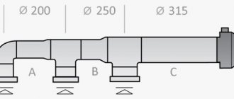
| Purpose of the duct | Main | Side branch | Distribution | Inlet grille | Exhaust grille |
| Recommended speed | From 6 to 8 m/s | From 4 to 5 m/s | From 1.5 to 2 m/s | From 1 to 3 m/s | From 1.5 to 3 m/s |
With natural impulse, the recommended flow rate in the system varies from 0.2 to 1 m/s, which also depends on the functional purpose of each air duct. In some exhaust shafts of high-rise buildings or structures, this value can reach 2 m/s.
Calculation order
Initially, the formula for calculating the speed of air flow in the channel is presented in reference books edited by I.G. Staroverova and R.V. Shchekin in the following form:
L = 3600 x F x ϑ, where:
- L – air mass flow in a given section of the pipeline, m³/h;
- F – channel cross-sectional area, m²;
- ϑ – air flow speed in the area, m/s.
Ventilation calculation table.
To determine the flow speed, the formula takes the following form:
ϑ= L / 3600 x F
It is from this that the actual air speed in the channel is calculated. This must be done precisely because of the standardized values of the diameter or dimensions of the pipe according to SNiP. First, the recommended speed for a particular purpose of the air duct is adopted and its cross-section is calculated. Next, the diameter of a circular channel is determined by reverse calculation using the formula for the area of a circle:
F = π x D2 / 4, here D is the diameter in meters.
The dimensions of a rectangular channel are determined by selecting the width and height, the product of which will give a cross-sectional area equivalent to the calculated one. After these calculations, the nearest normal dimensions of the air duct are selected (usually the larger one is accepted) and in reverse order the value of the actual flow velocity in the future duct is found. This value will be required to determine the dynamic pressure on the pipe walls and calculate pressure losses due to friction and local resistance of the ventilation system.
Do I need to rely on SNiP?
In all calculations that we carried out, the recommendations of SNiP and MGSN were used. This regulatory documentation allows you to determine the minimum permissible ventilation performance that ensures a comfortable stay for people in the room. In other words, SNiP requirements are aimed primarily at minimizing the cost of the ventilation system and the costs of its operation, which is important when designing ventilation systems for administrative and public buildings.
In apartments and cottages the situation is different, because you are designing ventilation for yourself, and not for the average resident, and no one forces you to adhere to the recommendations of SNiP. For this reason, system performance can be either higher than the design value (for greater comfort) or lower (to reduce energy consumption and system cost). In addition, everyone’s subjective feeling of comfort is different: for some, 30–40 m³/h per person is enough, but for others, 60 m³/h will not be enough.
However, if you do not know what air exchange you need to feel comfortable, it is better to follow the recommendations of SNiP. Since modern air handling units allow you to adjust the performance from the control panel, you can find a compromise between comfort and savings already during the operation of the ventilation system.
Online calculator for calculating ventilation performance
Calculation of ventilation, as a rule, begins with the selection of equipment that is suitable for such parameters as performance in terms of the volume of air pumped and measured in cubic meters per hour. An important indicator in the system is the air exchange rate. The air exchange rate shows how many times the air in the room is completely replaced within an hour. The air exchange rate is determined by SNiP and depends on:
- purpose of the premises
- quantity of equipment
- generating heat,
- number of people in the room.
In total, all values for the air exchange rate for all rooms constitute the air productivity.
Calculation of productivity by air exchange rate | Methodology for calculating ventilation by multiplicity: L = n * S * N, where: L—required productivity m3/h; n is the air exchange rate; S is the area of the room; H—room height, m. | |
Calculation of ventilation performance by number of people | ||
| Methodology for calculating ventilation performance by number of people: L = N * Lnorm, where: L—capacity m3/h; N is the number of people in the room; Lн - standard indicator of air consumption per person component: during rest - 20 m3/h; during office work - 40 m3/h; during active work - 60 m3/h. | ||
Design air exchange
The calculated value of air exchange is taken to be the maximum value from calculations of heat input, moisture input, harmful vapors and gases, sanitary standards, compensation for local exhaust hoods and the standard air exchange rate.
The air exchange of residential and public premises is usually calculated according to the air exchange rate or according to sanitary standards.
After calculating the required air exchange, an air balance of the premises is compiled, the number of air distributors is selected, and an aerodynamic calculation of the system is made. Therefore, we advise you not to neglect the calculation of air exchange if you want to create comfortable conditions for your stay in the room.
Why do they measure air speed?
For ventilation and air conditioning systems, one of the most important factors is the condition of the supplied air. That is, its characteristics.
The main air flow parameters include:
- air temperature;
- air humidity;
- air flow rate;
- flow rate;
- duct pressure;
- other factors (pollution, dust...).
SNiPs and GOSTs describe standardized indicators for each of the parameters. Depending on the project, the values of these indicators may vary within acceptable standards.
The speed in the air duct is not strictly regulated by regulatory documents, but in the designer's reference books you can find the recommended value of this parameter. You can find out how to calculate the speed in an air duct and become familiar with its permissible values by reading this article.
For example, for civil buildings the recommended speed of air movement through the main ventilation ducts is within 5-6 m/s. A correctly performed aerodynamic calculation will solve the problem of supplying air at the required speed.
But in order to constantly maintain this speed regime, you need to control the speed of air movement from time to time. Why? After some time, air ducts and ventilation channels become dirty, equipment may malfunction, and air duct connections become depressurized. Also, measurements must be carried out during routine inspections, cleanings, repairs, and in general, during ventilation maintenance. In addition, the speed of movement of flue gases, etc., is also measured.
Calculation of industrial ventilation
a) by excess sensible heat at the value of the angular coefficient of the process beam in the room ε
≥ 40000 kJ/kg
| (I.1) |
For rooms with heat and moisture release at the value of the angular coefficient of the process beam in the room ε
< 40000 kJ/kg air flow should be determined using formula (I.3) or (I.4).
The heat flow entering the room from direct and diffuse solar radiation should be taken into account when designing:
ventilation, including evaporative air cooling, for the warm season;
air conditioning - for warm and cold periods of the year and for transitional conditions;
b) by the mass of released harmful or explosive substances
| (AND 2) |
When several harmful substances that have a summation effect are simultaneously released into the room, air exchange should be determined by summing up the air flow rates calculated for each of these substances:
a) by excess moisture (water vapor)
| (I.3) |
For rooms with excess moisture, the sufficiency of air exchange should be checked to prevent the formation of condensation on the inner surface of the external enclosing structures at the design parameters B of the outside air during the cold season:
b) by excess total heat
| (I.4) |
c) according to the normalized air exchange rate
| L = Vpn ; | (I.5) |
d) according to the standardized specific flow rate of supply air:
| I.6 L = Ak ; | (I.6) |
| I.7L = | (I.7) |
In formulas (I.1) - (I.7):
Lw,z
— consumption of air removed from the serviced or working area of the premises by local suction systems and for technological needs, m3/h;
Q
,
Qh,f
- excess sensible and total heat flows in the room, assimilated by the air of central ventilation and air conditioning systems, W;
With
— heat capacity of air equal to 1.006 kJ/(kg °C);
tw,z
— temperature of air removed by local suction systems in the serviced or working area of the room, and for technological needs, °C;
t
1 - temperature of air removed from the room outside the serviced or working area, °C;
tin
— temperature of air supplied to the room, °C;
W
— excess moisture in the room assimilated by the air of central ventilation and air conditioning systems, g/h;
dw,z
— moisture content of air removed from the serviced or working area of the premises by local suction systems, and for technological needs, g/kg;
d
1 - moisture content of air removed from the premises outside the serviced or working area, g/kg;
d in
— moisture content of air supplied to the room, g/kg;
Iw,z
— specific enthalpy of air removed from the serviced or working area of the premises by local suction systems, and for technological needs, kJ/kg;
I
1 - specific enthalpy of air removed from the room outside the serviced or working area, kJ/kg;
Iin
— specific enthalpy of air supplied to the room, kJ/kg, determined taking into account the temperature increase in accordance with (I.6);
mro
— consumption of each of the harmful or explosive substances entering the air in the room, mg/h;
qw,z
,
q
1 - concentration of a harmful or explosive substance in the air removed, respectively, from the serviced or working area of the room and beyond, mg/m3;
qin
— concentration of harmful or explosive substance in the air supplied to the room, mg/m3;
Vp
— room volume, m3; for rooms with a height of 6 m or more should be taken
Vp
= 6
A
,
where A
— room area, m2;
N
— number of people (visitors), workplaces, pieces of equipment;
n
— normalized air exchange rate, h-1;
k
— standardized supply air flow per 1 m2 of room floor, m3/(h∙m2);
m
— standardized specific flow rate of supply air per person, m3/h, per workplace, per visitor or piece of equipment.
Air parameters tw,z
,
dw,z
,
Iw,z
should be taken equal to the calculated parameters in the serviced or working area of the premises according to Section 5 of this set of rules, and
qw,z
- equal to the maximum permissible concentration in the working area of the premises.
Some useful tips and notes
As can be understood from the formula (or when carrying out practical calculations on calculators), air speed increases as the pipe size decreases. A number of advantages can be derived from this fact:
- there will be no losses or the need to lay an additional ventilation pipeline to ensure the required air flow if the dimensions of the room do not allow for large ducts;
- it is possible to lay smaller pipelines, which in most cases is simpler and more convenient;
- the smaller the diameter of the channel, the cheaper its cost; the price of additional elements (dampers, valves) will also decrease;
- the smaller size of the pipes expands the installation possibilities; they can be positioned as needed, practically without adjusting to external constraining factors.
However, when laying air ducts of a smaller diameter, it must be remembered that as the air speed increases, the dynamic pressure on the pipe walls increases, and the system resistance also increases, which will require a more powerful fan and additional costs. Therefore, before installation, it is necessary to carefully carry out all calculations so that savings do not result in large costs or even losses, because a building that does not comply with SNiP standards may not be allowed to operate.
Formulas for calculation
To carry out all the necessary calculations, you need to have some data. To calculate air speed, you will need the following formula:
ϑ= L / 3600*F , where
ϑ – air flow speed in the pipeline of the ventilation device, measured in m/s;
L – air mass flow (this value is measured in m3/h) in the section of the exhaust shaft for which the calculation is being made;
F is the cross-sectional area of the pipeline, measured in m2.
Using this formula, the air speed in the duct is calculated, and its actual value is calculated.
From the same formula you can derive all other missing data. For example, to calculate air flow, the formula must be converted as follows:
L = 3600 x F x ϑ.
In some cases, such calculations are difficult to perform or there is not enough time. In this case, you can use a special calculator. There are many similar programs on the Internet. For engineering offices, it is better to install special calculators that are more accurate (they subtract the thickness of the pipe wall when calculating its cross-sectional area, put more decimal places in pi, calculate more accurate air flow, etc.).
Air flow
Knowing the speed of air movement is necessary in order to calculate not only the volume of supply of the gas mixture, but also to determine the dynamic pressure on the walls of the channels, losses due to friction and resistance, etc.
Description of the ventilation system
Air ducts are certain elements of the ventilation system that have different cross-sectional shapes and are made of different materials. To make optimal calculations, you will need to take into account all the dimensions of the individual elements, as well as two additional parameters, such as the volume of air exchange and its speed in the duct cross-section.
Violation of the ventilation system can lead to various diseases of the respiratory system and significantly reduce the resistance of the immune system. Also, excess moisture can lead to the development of pathogenic bacteria and the appearance of fungus. Therefore, when installing ventilation in homes and institutions, the following rules apply:
A ventilation system must be installed in each room. It is important to maintain air hygiene standards. Places with different functional purposes require different ventilation system equipment designs.
In this video we will look at the best combination of hood and ventilation:
This is interesting: calculating the area of air ducts.
The importance of proper air exchange
The main purpose of ventilation is to create and maintain a favorable microclimate inside residential and industrial premises.
If the air exchange with the outside atmosphere is too intense, then the air inside the building will not have time to warm up, especially in the cold season. Accordingly, the rooms will be cold and not humid enough.
Conversely, with a low rate of renewal of the air mass, we get a waterlogged, excessively warm atmosphere, which is harmful to health. In advanced cases, the appearance of fungi and mold on the walls is often observed.
We need a certain balance of air exchange that will allow us to maintain humidity levels and air temperatures that have a positive effect on people’s health. This is a major problem that needs to be solved.
Air exchange depends mainly on the speed of air passage through the ventilation ducts, the cross-section of the air ducts themselves, the number of bends in the route and the length of sections with smaller diameters of air-conducting pipes.
All these nuances are taken into account when designing and calculating the parameters of the ventilation system.
These calculations make it possible to create reliable indoor ventilation that meets all standard indicators approved in the “Building Codes and Rules”.