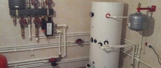
Schemes and types of designs of UTK mixing units
By default, the UTK temperature control mixing unit, version 0, without fittings, flexible hoses and thermomanometers is offered for sale. It is possible to manufacture non-standard piping units according to sketches and technical specifications of the customer.
The mixing unit is built according to a three-way control scheme
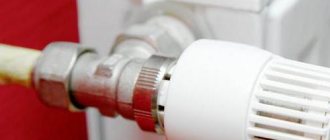
- Ball valves 1 serve to disconnect the unit from the heating network.
- There is a filter 2 for hot water on the supply line of the unit. When dirty, the filter element must be cleaned.
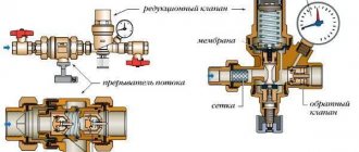
- A three-way control valve with a servo drive 3 of proportional control is installed on the supply line of the unit. Input B of the valve is connected by a bypass to the return line of the unit.
- A check valve 5 is installed on the bypass to prevent coolant from flowing from the supply line to the return line, bypassing the air heater.
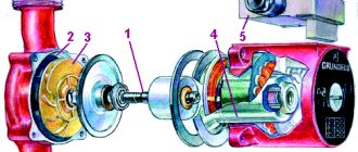
- A circulation pump 4 is installed on the supply line of the unit to ensure circulation of the coolant through the “small” circuit.
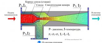
Operating principle of the mixing unit (thermal control unit) UTK
When fully open, the valve ensures circulation of the coolant along the “large” circuit (flow direction A-AB), thereby achieving the maximum thermal power of the unit. In a completely closed state, the valve ensures circulation along a “small” circuit (flow direction B-AB), thereby achieving the minimum thermal power of the unit. In intermediate positions, the valve ensures circulation through a “small” circuit with a mixture of coolant from the network.
The warranty period for thermal control units is 3 years.
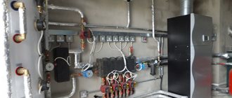
It is possible to manufacture any non-standard thermal control units according to customer designs.
Diagrams of non-standard piping units for water heaters:
Price for mixing unit depends on its size and the pump used. You can find prices for mixing units of the UTK series in our price list.
ATTENTION!
Qualified, specially trained personnel are allowed to install and assemble mixing units. When commissioning and further operation of the mixing unit, it is necessary to ensure the presence of coolant in the heating network.
Requirements for connecting and installing the mixing unit
- When installing, assembling and putting into operation, it is necessary to comply with the rules for the technical operation of consumer electrical installations (PTEEP) and inter-industry rules for labor protection (safety rules) for the operation of electrical installations (POT RM-016-2001), “Safety rules for the operation of heat-using installations and thermal networks" and SNiP 41-01-2003.
- Installation and commissioning of the mixing unit can only be carried out by a specialized installation organization.
- Before installation, it is necessary to check the condition of the components of the mixing unit, the insulation of the drive and pump wires.
- If the coolant is water, the mixing unit may only be installed inside heated rooms in which the temperature does not drop below +5 degrees. WITH.
- If the coolant is non-freezing liquids, the mixing unit may be installed inside unheated rooms.
- The mixing unit should be installed so that the axis of the circulation pump is horizontal, and the location of the pump terminal box and valve drive should prevent moisture from entering them in the event of a leak.
- The electrical connection of the pump must be made using a three-wire cable to a network with alternating current 230 V, 50 Hz. Terminals L (phase), N (zero) and PE (ground) are located in the junction box located on the pump body. They can be accessed by unscrewing the screw in the middle of the box.
- The connected electrical cable is routed through a sealing ring on the side of the box.
- Until the electrical connection is completed, the power cable must be disconnected from the power supply.
- It is prohibited to carry out maintenance work on a running mixing unit, including the coolant path under pressure.
Main technical characteristics of control valve drives
| Technical specifications | TR24-SR | LR24A-SR | NR24A-SR |
| Rated voltage | 24 V~ 50 Hz; 24 VDC | 24 V~ 50 Hz; 24 VDC | 24 V~ 50 Hz; 24 VDC |
| Power consumption | 0.5 W | 1.0 W | 1.5 W |
| Control | Control signal 0-10 V (2-10 V) | ||
| Connection, power cable | 3x0.75 mm² | ||
| Manual control | The gearbox is disengaged using a self-resetting button, or by pressing the drive handle (for the “TR” drive) | ||
| Turning time/turning angle | 90 sec / 95° | ||
| Housing protection degree, IP | 54 | ||
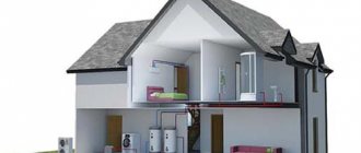
Operating principle of the mixing unit
The water boiler heats the liquid to a temperature of 95 degrees. Water at this temperature is only used in central heating radiators. For heated floors it is very hot.
When exposed to water at elevated temperatures, harmful substances can be released from floor coverings. In addition, the surface of the finishing material may rise from hot water and the coating will deteriorate. And a person feels uncomfortable on such a floor.
The coolant supplied by the supply pipe to the circuit must be no more than 55 degrees in order to heat the floor covering to 30 degrees.
Therefore, a water mixing unit is needed, which helps cool the hot liquid.
The coolant from the boiler is supplied directly to the mixing unit of the “water heated floor” heating system. The thermostat, having determined that the water temperature is very high, opens the safety valve, which allows water from the return line. The return pipe is part of the mixing unit for a heated floor, through which water flows into the circuits. Having given up heat to the circuit, it cools down and returns to it already cold. The mixing unit not only regulates the temperature of the water in the pipelines, but also promotes the circulation of water in them. In order for the water to heat up evenly throughout all the pipes, the circulation pump circulates it in a circle.
Brief overview of modern models
To get an impression of the brands and models of water heaters, let’s look at several devices from different manufacturers.
Heaters KSK-3, produced at the company T.S.T.
Specifications:
- coolant temperature at the inlet (outlet) - +150°C (+70°C);
- inlet air temperature – from -20°С;
- working pressure – 1.2 MPa;
- maximum temperature - +190°C;
- service life – 11 years;
- working resource – 13,200 hours.
External parts are made of carbon steel, heating elements are made of aluminum.
The Volcano mini water fan heater is a compact device from the Polish brand Volcano, characterized by practicality and ergonomic design. The air flow direction is adjusted using controlled blinds.
Specifications:
- power within 3-20 kW;
- maximum productivity 2000 m?/h;
- heat exchanger type – double row;
- protection class – IP 44;
- maximum coolant temperature 120°C;
- maximum working pressure 1.6 MPa;
- internal volume of the heat exchanger is 1.12 l;
- guide blinds.
Galletti AREO heater made in Italy. The models are equipped with a fan, a copper-aluminum heat exchanger and a drainage tray.
Specifications:
- power in heating mode – from 8 kW to 130 kW;
- power in cooling mode – from 3 kW to 40 kW;
- water temperature – + 7°C +95°C;
- air temperature – 10°C + 40°C;
- working pressure – 10 bar;
- number of fan speeds – 2/3;
- electrical safety class IP 55;
- motor protection.
In addition to the devices of the listed brands, on the market of heaters and water air heaters you can find models of the following brands: Teplomash, 2VV, Fraccaro, Yahtec, Tecnoclima, Kroll, Pakole, Innovent, Remko, Zilon.
Installation of a "warm floor" mixing unit
The main element of the mixing unit for heating is the valve, which is responsible for mixing the coolants. It can be two-way or three-way.
The two-way valve consists of a thermostat head that houses a fluid sensor inside. This sensor, when the coolant is supplied, records its temperature. If it exceeds the norm, then the head rotates, thereby closing the entrance to the circuit. Usually the cooled liquid from the return line is always open. The hot coolant is passed to the pipes only when the temperature of the heated floor drops. A two-way valve copes well with a system in a small room, because it passes coolant into only one circuit.
If you need to heat an apartment of more than 200 square meters, then you need to use a three-way valve (a two-way valve has a low throughput). Such a valve has three connections, i.e. it serves not one, but several circuits. It mixes hot and cold water. It also redistributes flows with liquid of different temperatures. The three-way valve is equipped with a servo drive, which regulates its operation.
The main part of this part of the system is a damper, which is placed so that water is mixed in a certain amount when the flows of cold and hot coolant intersect. It can be adjusted according to standards. You can move the damper in the other direction, thereby increasing the flow of hot water if the temperature outside has dropped. It is located at the meeting point of hot and cold flows near the boiler. Unlike a two-way valve, the hot water supply is not shut off. The amount of hot and cold coolant depends on the position of the damper: which water it lets through in a larger ratio, and which in a smaller ratio. Mixing, the flows form a coolant of a certain temperature.
A significant disadvantage of a three-way valve is the possibility of passing a whole stream of hot water into the circuit. Then the coolant pressure increases, which can damage the pipes. Hot water entering the water heated floor system can heat up the coating so much that you can get burned and damage the finishing material.
Mixing heated floors also include weather-dependent sensors .
If the air temperature has increased, the supply of cold water may increase.
When the temperature decreases in cold weather, the flow of hot water can increase its intensity.
An important part of the system is the secondary circuit balancing valve . It mixes hot water from the supply pipe and cold water from the return pipe in the proportions required for heating. The valve's capacity is indicated by the scale on it. To avoid accidentally changing the position of the balancing valve, it is secured with a clamping key. You can use a hex wrench to change the valve setting.
The balancing shut-off valve connects the mixing unit for heated floors with all elements of the system.
The bypass valve protects the circulation pump from damage due to the drop in pressure that occurs when water flow through the pump is accidentally stopped.
Its purpose is to maintain water pressure. When it falls, the valve is activated. As a result, hot water flows through the bypass (reserve path in emergency condition) to the central heating radiators.