What to do if you need a very accurate calculation
Unfortunately, not every apartment can be considered standard. This applies even more to private residential buildings. The question arises: how to calculate the number of heating radiators, taking into account the individual conditions of their operation? To do this, you will need to take into account many different factors.
When calculating the number of heating sections, you need to take into account the height of the ceiling, the number and size of windows, the presence of wall insulation, etc.
The peculiarity of this method is that when calculating the required amount of heat, a number of coefficients are used that take into account the characteristics of a particular room that can affect its ability to store or release thermal energy. The formula for calculations looks like this:
KT = 100W/sq.m. * P * K1 * K2 * K3 * K4 * K5 * K6 * K7. Where
KT - the amount of heat required for a specific room; P - room area, sq.m.; K1 - coefficient taking into account the glazing of window openings:
- for windows with conventional double glazing - 1.27;
- for windows with double glazing - 1.0;
- for windows with triple glazing - 0.85.
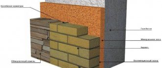
K2 - coefficient of thermal insulation of walls:
- low degree of thermal insulation - 1.27;
- good thermal insulation (two bricks or a layer of insulation) - 1.0;
- high degree of thermal insulation - 0.85.
K3 - ratio of window area to floor area in the room:
K4 is a coefficient that allows you to take into account the average air temperature in the coldest week of the year:
- for -35 degrees - 1.5;
- for -25 degrees - 1.3;
- for -20 degrees - 1.1;
- for -15 degrees - 0.9;
- for -10 degrees - 0.7.
K5 - adjusts the heat demand taking into account the number of external walls:
K6 - taking into account the type of room located above:
- cold attic - 1.0;
- heated attic - 0.9;
- heated living space - 0.8
K7 - coefficient taking into account the height of the ceilings:
This calculation of the number of heating radiators includes almost all the nuances and is based on a fairly accurate determination of the room’s need for thermal energy.
All that remains is to divide the obtained result by the heat transfer value of one section of the radiator and round the resulting result to a whole number.
Some manufacturers offer an easier way to get the answer. On their websites you can find a convenient calculator specifically designed to make these calculations. To use the program, you need to enter the required values in the appropriate fields, after which the exact result will be given. Or you can use special software.
When we got an apartment, we didn’t think about what kind of radiators we had and whether they suited our house. But over time, a replacement was required and they began to approach it from a scientific point of view. Since the power of the old radiators was clearly not enough. After all the calculations we came to the conclusion that 12 is enough. But you also need to take into account this point - if the TEC does not do its job well and the batteries are a little warm, then no amount will save you.
I liked the last formula for a more accurate calculation, but the coefficient K2 is not clear. How to determine the degree of thermal insulation of walls? For example, a 375mm thick wall made of GRAS foam block, is it low or medium? And if you add 100mm of dense construction foam to the outside of the wall, will it be high, or still medium?
Ok, the last formula seems to be good, windows are taken into account, but what if the room also has an external door? What if this is a garage with 3 windows 800*600 + door 205*85 + sectional garage doors 45mm thick with dimensions 3000*2400?
If you do it for yourself, I would increase the number of sections and install a regulator. And voila - we are already much less dependent on the whims of the thermal power plant.
Calculation of parameters for heating automation cabinets
Every year, technology development occurs more and more rapidly and very few processes in production can already be done without automation. It is very important to keep equipment that automates production processes in working order for as long as possible, so solutions for its protection are constantly being improved.
The most optimal way to preserve electrical appliances is to place them in special protective electrical cabinets, called automation and control cabinets. Such electrical panels are metal cabinets that can protect equipment from humidity, dust, water droplets and other negative factors.
However, even inside the automation cabinet itself there are a number of conditions that can also negatively affect the operation of electrical components located inside. In this article we will look at some of them in detail.
High cabinet temperature
When almost any electrical equipment operates, a certain amount of heat is generated. This is especially noticeable in the hot season, when heating of equipment can lead to overheating and failure. To avoid this situation, forced air cooling in the control cabinet is necessary. Fans for the control room can help with cooling.
Low ambient temperature
Cold can cause no less damage to electrical equipment than overheating. Most devices are not designed to operate at low air temperatures, and negative air temperatures in winter do not allow them to start at all.
Therefore, for automation cabinets located outdoors or in poorly heated rooms, it is necessary to ensure proper heating in the winter.
Not only does low air temperature itself have a bad effect on equipment, it also causes condensation to form on the interior surfaces of the cabinet when the air temperature inside reaches the dew point.
The dew point is the extreme air temperature at a certain humidity, below which water vapor begins to condense. In the table you can see dew point data for a certain humidity and ambient temperature.
| Relative humidity, % | Ambient temperature, °C | |||||||
| 20 | 25 | 30 | 35 | 40 | 45 | 50 | 55 | |
| 40 | 6 | 11 | 15 | 19 | 24 | 28 | 33 | 37 |
| 50 | 9 | 14 | 19 | 23 | 28 | 32 | 37 | 41 |
| 60 | 12 | 17 | 21 | 26 | 31 | 36 | 40 | 45 |
| 70 | 14 | 19 | 24 | 29 | 34 | 38 | 43 | 48 |
| 80 | 16 | 21 | 26 | 31 | 36 | 41 | 46 | 51 |
| 90 | 18 | 23 | 28 | 33 | 38 | 43 | 48 | 53 |
| 100 | 20 | 25 | 30 | 35 | 40 | 45 | 50 | 55 |
In order to neutralize all the negative conditions for the operation of electrical appliances in automation cabinets, it is necessary to calculate the exact power of the heating elements, which is necessary to heat the air to the optimal temperature. The calculation formula is based on many different parameters, which in turn also need to be correctly calculated and taken into account. Based on the received power, the most suitable heating equipment is selected: OSHA heaters, fans, thermostats.
Location and dimensions of the automation cabinet body
First, you need to calculate the area of the walls of the automation cabinet body based on its dimensions. Then, depending on the location of the control cabinet, you need to determine which walls of the control cabinet will dissipate heat. Obviously, the dissipation area will be larger in free-standing electrical cabinets, and control panels in the middle of a row of similar panels will not be in contact with the environment on all sides of the housing, therefore, the dissipation surface area will be smaller.
To organize cooling of the automation cabinet, it would be better if the heat dissipation area is as large as possible. For example, if you have the same set of electrical appliances, then cooling them in a larger control cabinet will be much easier than in a compact electrical panel. But for cooling it’s quite the opposite: it’s easier to heat the air in a small cabinet.
For each control cabinet placement option, you can use ready-made formulas that will help you easily and quickly calculate the dissipation area of the cabinet body surface.
| Cabinet location | Calculation formula |
| Separate accommodation | A = 1.8 H (W + D) + 1.4 W D |
| Wall location | A = 1.4 W (H + D) + 1.8 D H |
| Last place in a row of cabinets | A = 1.4 D (H + D) + 1.8 W H |
| The last place in a row on the wall | A = 1.4 H (W + D) + 1.4 W D |
| Position in the middle of the row | A = 1.8 W H + 1.4 W D + D H |
| In the middle of the row on the wall | A = 1.4 W (H + D) + D H |
| Location on the wall in the middle of the row under the canopy | A = 1.4 W H + 0.7 W D + D H |
Heat flux density
Heat flux density is an indicator of the rate of heat dissipation inside the electrical control panel. This parameter directly depends on atmospheric pressure, so it is very easy to calculate it from the table, knowing the altitude above sea level for the area.
The higher the pressure, the better the heat will dissipate, therefore, cabinets located higher above sea level in an area with lower pressure will dissipate less heat.
For the central zone of the Russian Federation, the heat flux density is 3.2 at an average height above sea level of 170 m.
Thermal conductivity of electrical cabinet housing materials
When calculating the heating power of automation cabinets, the material from which it is made is also important. A parameter such as the heat transfer coefficient depends on the type of metal.
The heat transfer coefficient is a certain amount of heat transferred per unit time through 1 m2 of effective heat exchange surface from a more heated zone to a less heated one.
Let's take as an example the three most common types of metals for control cabinets: painted sheet steel, stainless steel and aluminum. Aluminum has the highest heat transfer coefficient (12), followed by painted steel (5.5), and stainless steel has the lowest (4.5). Based on this, we see that if cooling is necessary, it is better to use aluminum cabinets, as they will dissipate heat well. Due to its good heat transfer, aluminum is used in most types of radiators, in particular in OSHA heaters from the manufacturer The thermoelement radiator is also made of aluminum.
Heat generation by equipment in the automation cabinet
The composition of the set of electrical appliances located in the control cabinet is also an important indicator in power calculations. After all, many types of electrical equipment are capable of generating large amounts of heat when heated and even require additional cooling during the hot season. Among the electrical appliances placed in automation cabinets there are many power supplies, solid-state relays, transformers, frequency converters and other elements. Each of them generates a certain amount of thermal energy and this must also be taken into account when calculating.
Calculation of temperature inside the control room
The formula for calculating the temperature inside the control cabinet is as follows:
Tvnut = Qv * k * A + Tnar
Tvnut – air temperature inside the automation panel,
Tnar – outside air temperature,
Qv – heat release from electrical appliances installed in the control room
k – heat transfer coefficient of the metal from which the automation cabinet body is made
A – effective heat exchange surface area
You can quickly calculate heat generation using the formulas presented in this table:
| Device | Formula for calculation |
| Frequency converters | Qpch = total power * 0.05 |
| Power supplies | Qbp = total power * 0.1 |
| Slot machines | Qa = total current * 0.2 |
| Starters | Qп = total current * 0.4 |
| Transformers | Qt = total power * 0.1 |
| Solid State Relays | Qр = total load current for each phase * 1.2 |
The total heat release of the components Qv is then calculated as the total value of the heat release of all electrical appliances.
Based on the results of calculating the internal temperature of the control cabinet, we can compare the calculated value with the optimal temperature for the equipment placed in it. If the temperature inside the cabinet is higher than recommended, you need to cool the air using fans.
If the temperature is not high enough, it is necessary to heat the control room using OSHA heaters. To select the most suitable heater models, you need to determine what total power of the heating elements is needed to maintain the most suitable air temperature in the cabinet.
Accurate heat load calculations
Thermal conductivity value and heat transfer resistance for building materials
But still, this calculation of the optimal heat load for heating does not provide the required calculation accuracy. It does not take into account the most important parameter - the characteristics of the building. The main one is the heat transfer resistance of the material used to manufacture individual elements of the house - walls, windows, ceilings and floors. They determine the degree of conservation of thermal energy received from the coolant of the heating system.
What is heat transfer resistance (R)? This is the reciprocal of thermal conductivity (λ) - the ability of the material structure to transmit thermal energy. Those. the higher the thermal conductivity value, the higher the heat losses. This value cannot be used to calculate the annual heating load, since it does not take into account the thickness of the material (d). Therefore, experts use the heat transfer resistance parameter, which is calculated using the following formula:
Calculation of walls and windows
Heat transfer resistance of walls of residential buildings
There are standardized values for the heat transfer resistance of walls, which directly depend on the region where the house is located.
In contrast to the enlarged calculation of the heating load, you first need to calculate the heat transfer resistance for the external walls, windows, ground floor floor and attic. Let's take the following characteristics of the house as a basis:
- Wall area – 280 m². It includes windows - 40 m²;
- The material used for making the walls is solid brick (λ=0.56). The thickness of the external walls is 0.36 m. Based on this, we calculate the TV transmission resistance - R = 0.36/0.56 = 0.64 m²*C/W;
- To improve the thermal insulation properties, external insulation was installed - polystyrene foam 100 mm thick. For him λ=0.036. Accordingly, R=0.1/0.036= 2.72 m²*C/W;
- The overall R value for external walls is 0.64 + 2.72 = 3.36 which is a very good indicator of the thermal insulation of a house;
- The heat transfer resistance of windows is 0.75 m²*C/W (double glazing filled with argon).
In fact, heat losses through the walls will be:
(1/3.36)*240+(1/0.75)*40= 124 W at a temperature difference of 1°C
We will take the same temperature indicators as for the aggregate calculation of the heating load +22°C indoors and -15°C outdoors. Further calculations must be made using the following formula:
Ventilation calculation
Then it is necessary to calculate the losses through ventilation. The total air volume in the building is 480 m³. Moreover, its density is approximately 1.24 kg/m³. Those. its mass is 595 kg. On average, air is renewed five times per day (24 hours). In this case, to calculate the maximum hourly heating load, you need to calculate the heat losses for ventilation:
(480*40*5)/24= 4000 kJ or 1.11 kW/hour
By summing up all the obtained indicators, you can find the total heat loss of the house:
This way the exact maximum heating load is determined. The resulting value directly depends on the outside temperature. Therefore, to calculate the annual load on the heating system, changing weather conditions must be taken into account. If the average temperature during the heating season is -7°C, then the total heating load will be equal to:
(124*(22+7)+((480*(22+7)*5)/24))/3600)*24*150(heating season days)=15843 kW
By changing the temperature values, you can make an accurate calculation of the heat load for any heating system.
To the results obtained, you need to add the value of heat losses through the roof and floor. This can be done by a correction factor of 1.2 - 6.07 * 1.2 = 7.3 kW/h.
The resulting value indicates the actual energy costs during system operation. There are several ways to regulate the heating load. The most effective of them is reducing the temperature in rooms where there is no constant presence of residents. This can be done using thermostats and installed temperature sensors. But at the same time, a two-pipe heating system must be installed in the building.
To calculate the exact value of heat losses, you can use the specialized Valtec program. The video shows an example of working with it.
Anatoly Konevetsky, Crimea, Yalta
Anatoly Konevetsky, Crimea, Yalta
Dear Olga! Sorry to contact you again. According to your formulas, I get an unimaginable heat load: Kir=0.01*(2*9.8*21.6*(1-0.83)+12.25)=0.84 Qot=1.626* 25600*0.37*((22-(-6))*1.84*0.000001=0.793 Gcal/hour According to the aggregated formula given above, it turns out to be only 0.149 Gcal/hour. I can’t understand what’s the matter? Please explain! Sorry for disturbing you. Anatoly.
Anatoly Konevetsky, Crimea, Yalta
Pk = Pv – Pr [Watt], where
- Pk [Watt] – power of the cooling/heating device.
- Pv [Watt] - heat loss from dissipation.
- Pr [Watt] – heat radiation/heat transfer.
Heat loss from dissipation
- thermal energy generated inside the cabinet due to heating of operating devices.
To find out this value, you should look at the technical specifications of the installed equipment; some of them give the value of heat losses. For other devices, losses should be assumed to be approximately 10% of the total power consumption (this can also be found in the technical specifications). It is necessary to know the efficiency and degree of load to more accurately calculate the heat loss of an individual electrical component.
For example, if the efficiency of a frequency converter is 95%, then roughly 5% of its power consumption is spent on heating. If during operation this converter operates at 70% of its nominal value, then the power of its heat losses will be
70 · 5 / 100 % = 3,5 %
Thus, the thermal power of the cabinet will be equal to the sum of the heat losses of all devices installed in it.
Heat radiation/body loss
— heat transfer through the body of the electrical cabinet (not taking into account the insulation coefficient). The heat output of the cabinet is calculated using the formula below and measured in Watts:
Typical calculation of air conditioner power
A typical calculation allows you to find the power of an air conditioner for a small room: a separate room in an apartment or cottage, an office with an area of up to 50 - 70 m² and other premises located in permanent buildings. Calculation of cooling capacity Q
(in kilowatts) is produced according to the following procedure:
Q = Q1 + Q2 + Q3
| Q1 heat gains from windows, walls, floors and ceilings. | Q1 = S * h * q / 1000, where S room area (m²); h room height (m); q coefficient equal to 30 - 40 W/m³: q = 30 for a shaded room; q = 35 at average illumination; q = 40 for rooms that receive a lot of sunlight. If the room receives direct sunlight, the windows should have light-colored curtains or blinds. |
| Q2 is the sum of heat inflows from people. | Heat gain from an adult: 0.1 kW in a quiet state; 0.13 kW when driving lightly; 0.2 kW during physical activity; |
| Q3 is the sum of heat inflows from household appliances. | Heat gains from household appliances: 0.3 kW from the computer; 0.2 kW from TV; For other appliances, it can be assumed that they generate 30% of the maximum power consumption as heat (that is, the average power consumption is assumed to be 30% of the maximum). |
The power of the air conditioner must be within the Qrange
from
–5%
to
+15%
of design power
Q.
Example of a typical air conditioner power calculation
Let's calculate the power of the air conditioner for a living room with an area of 26 m² with a ceiling height of 2.75 m in which one person lives, and also has a computer, TV and a small refrigerator with a maximum power consumption of 165 W. The room is located on the sunny side. The computer and TV do not work at the same time, since they are used by one person.
- First, we determine the heat inflows from the window, walls, floor and ceiling. Coefficient q
let’s choose equal to
40
, since the room is located on the sunny side:Q1 = S * h * q / 1000 = 26 m² * 2.75 m * 40 / 1000 = 2.86 kW
.
- Heat inflows from one person in a calm state will be 0.1 kW
.
Q2 = 0.1 kW - Next, let’s find heat inflows from household appliances. Since the computer and TV do not work at the same time, only one of these devices needs to be taken into account in the calculations, namely the one that generates more heat. This is a computer whose heat output is 0.3 kW
.
The refrigerator emits about 30% of the maximum power consumption as heat, that is, 0.165 kW * 30% / 100% ≈ 0.05 kW
.
Q3 = 0.3 kW + 0.05 kW = 0.35 kW - Now we can determine the design power of the air conditioner: Q = Q1 + Q2 + Q3 = 2.86 kW + 0.1 kW + 0.35 kW = 3.31 kW
- Recommended power range Qrange
(from
-5%
to
+15%
of design power
Q
):
3.14 kW range
All we have to do is choose a model of suitable power. Most manufacturers produce split systems with capacities close to the standard range: 2,0
kW;
2.6
kW;
3.5
kW;
5.3
kW;
7.0
kW.
From this range we choose a model with a power of 3.5
kW.
BTU
(
BTU
) British Thermal Unit. 1000 BTU/hour = 293 Watts.
BTU/hour
.
Heat dissipation of equipment power calculation - All about electricity
- 1 Power calculation
- 2 Calculation of heat balance in an electrical cabinet 2.1 Pk=Pv– Pr [Watt], where
- 2.2 Pr= k · A · ∆T[Watt], where
- 2.3 ∆T = Ti – Ta, where
- 2.4 Pk = Pv – k A ∆T [Watt]
- 2.5 It is necessary to establish the thermal balance of a free-standing electrical cabinet with dimensions of 2000x800x600mm, made of steel, with a protection degree of at least IP54. The thermal energy loss of all components in the cabinet is Pv = 550 W.
- 2.6 It is necessary, using calculations, to select devices for maintaining the microclimate in the cabinet installed in the room. The cabinet is made of steel, the degree of protection is not lower than IP54, its dimensions are 2000x800x600mm. The thermal energy losses of all devices are known and amount to Pv = 550 W. It is required to ensure the internal temperature in the cold period is not lower than Ti = +15оС, and in the summer – not higher than Ti = +35оС. The external temperature is: in winter Ta = 0°C, in summer Ta = +30°C.
- 2.7 V = 3.1 Pv / ∆T [m3/h]
On this page you can calculate the required air conditioner power for a standard room (apartment or office). Please fill out the calculation form to select an air conditioner. Cooling capacity calculations are approximate.
To calculate multi-split systems for 2 or more rooms, it is better to contact our staff.
For a more accurate calculation of complex premises, taking into account the specifics of your wishes, it is recommended to contact our specialists. We will make calculations and subsequently install the air conditioner on your terms.
Air conditioner selection calculator
When determining the required power of an air conditioner, for an approximate calculation, you can take: one kilowatt of cooling capacity corresponds to ten square meters of area of the air-conditioned room.
For example, in a room of twenty square meters you will need to install an air conditioner with a cold capacity of at least 2.0 kW. For the correct selection of an air conditioner, based on accurate calculations, it is necessary to additionally calculate the heat input, which must be compensated by the cooling capacity of the air conditioner.
The power of the air conditioner (Qcond) for cold must be higher than the calculated value of the total heat input for a given room (Qtotal), which is calculated by the formula:
Qcond ≥ Qtotal = Q1+Q2+Q3+Q4+Q5 (kW), where:
- Q1 – heat gain from solar radiation, and when using electric lighting - from artificial light;
- Q2 – heat gain from people in the room;
- Q3 – heat input from office equipment;
- Q4 – heat input from household appliances;
- Q5 – heat input from heating.
Heat gain from solar radiation
In most cases, this is precisely the reason for the need to air condition the room. Heat gain from solar radiation depends on the area of the windows and their orientation to the cardinal points.
To buy an air conditioner in Moscow and the Moscow region, you must take into account that the heat gain through one square meter of glazing will be:
- north side – 81 W/m2;
- south side – 198 W/m2;
- southeast side – 244 W/m2;
- northwest side – 302 W/m2;
- southwest side – 302 W/m2;
- northeast side – 337 W/m2;
- east side – 337 W/m2;
- western side – 395 W/m2.
If the glazing is horizontal - 576 W/m2.
If the window is shaded by trees or there are thick, light-colored blinds, then the heat gain will be less. Therefore, the given values are divided by a factor of 1.4.
If the heat gain into the premises through glazing is less than the heat gain from artificial lighting, then the power of the lighting devices is taken into account. Heat gains from incandescent lamps are equal to their power. For fluorescent lamps, a coefficient of 1.16 is used.
If the lighting of the room meets the requirements of established standards, then the heat gain from artificial light can be taken at the standard calculation of 25...30 W per 1 m3.
Heat gains from the walls can be ignored if their thickness and thermal insulation are sufficient.
Heat gain from people in the room
To select an air conditioner, heat flow from people is taken into account. One person, depending on his occupation, identifies:
- rest in a sitting position – 120 W;
- light work in a sitting position – 130 W;
- moderately active work in the office – 140 W;
- light work, standing – 160 W;
- light work in production – 240 W;
- moderate work in production – 290 W;
- heavy work - 440 W.
Recommendations for choosing the type of air conditioner
Air conditioner for server cabinets
Not every climate system can withstand difficult operating conditions with continuous load. It must be equipped with a dust filter, dehumidifier, and winter kit. One of the air cooling options is a server cabinet with air conditioning. The design does not require condensate drainage, the outdoor unit is compact in size. The internal module is installed vertically or horizontally inside the server cabinet.
Requirements for air conditioners
When maintaining the climate in server rooms, uninterrupted operation of air conditioners is important. Breakdown and repair will leave telecommunications equipment without cooling for a long time. The principle of rotation and redundancy allows the requirement to be met. Several climate control units are installed in the room, united into one network by a rotating device. If one air conditioner malfunctions, the backup option is automatically switched on.
Alternating switching on of the blocks allows you to distribute the load in a balanced manner and ensure optimal climate parameters. In this mode, the equipment alternately stops for rest and maintenance.
A rotation unit helps control the air conditioning of server rooms. It automatically alternates between switching on working settings and, if necessary, connects a backup device. The second control option is to install sensors, the readings of which are displayed on a computer monitor. To determine the conditions in the server room, you do not have to leave your workplace. All information in the form of tables and graphs is sent to the computer. Messages are accompanied by a sound signal.
Split systems
Diagram of a column air conditioner
To maintain the specified parameters, split systems are used in server rooms. Domestic or semi-industrial high-power systems are installed in small rooms with heat release up to 10 kW. According to the type of installation they are:
- Wall mounted – a universal and affordable option. Productivity is 2.5-5 kW; a model is selected that provides a significant length of the freon route. Recommended manufacturers: Daikin, Toshiba and Mitsubishi Electric.
- Duct - devices are placed under a suspended ceiling, save space and provide effective air exchange. Suitable for large server rooms. Ducted air conditioning supplies cold air directly to the racks.
- Columned - powerful systems in the form of cabinets are installed on the floor and do not require installation.
Precision climate systems
Precision air conditioners for server rooms are professional equipment. Climate control systems have a long service life of continuous operation and allow you to maintain optimal temperature and humidity parameters. One of the advantages of the equipment is its accuracy; climatic indicators in large areas have fluctuations of no more than 1°C and 2%. Cabinet and ceiling models are installed in server rooms. The first ones are characterized by bulky dimensions, their power is 100 kW. Ceiling systems are less efficient (20 kW) and are installed in rooms where it is not possible to place cabinet air conditioners.
Types of precision climate control devices
Climate control systems can be monoblock or separate, like split systems. The system is cooled in various ways: by evaporation of freon, water or air circuit. Popular manufacturers: UNIFLAIR, Blue box.
Advantages of installations:
- uninterrupted operation;
- high power equipment;
- precise control of climatic components;
- wide range of operating temperatures;
- combination with dispatch control.
Disadvantages of precision systems:
- high price;
- noisy monoblock design.
Chiller fan coil system
The air conditioning system uses water or a mixture of ethylene glycol as the coolant. The operating principle is similar to installations with freon. The chiller cools the liquid circulating in the fan coil heat exchanger, air passing through the radiator lowers the temperature.
- high performance;
- versatility;
- safe and accessible operation.
Heat gains from welding transformers.
Welding transformers can be placed in the room where welding work is carried out and outside this room. All electrical power supplied to transformers is converted into heat.
If welding work is carried out in the same room where the transformers are installed, the heat generation from them will be:
Qtr. = 1000 ∑Nset × Codn × Kzagr × Kisp × Kt, W
where: ∑Nset - the total installed power of transformers, in kW - is accepted according to the passport); Kodn - the simultaneity coefficient is accepted in the range of 0.5 ÷ 1 - with several units of installed equipment, some of them may not work; Kzagr - load factor in fractions of a unit accepted within the range of 0.5 ÷ 0.8 or as specified by electrician-technologists; Kisp - power utilization factor in fractions of a unit, accepted within the range 0.7 ÷ 0.9; Kt - coefficient taking into account the amount of heat supplied to the air in the room from processed parts that are in the room for a limited time.
This coefficient can be determined by calculating the heat input from cooling materials.
Qcooling = C × G ( tmat. - tv ), kJ
C is the specific heat capacity of the material of the cooling product, kJ/(kg × ºС); G is the mass of the cooling product, kg; tmat. — initial temperature of the product material, ºС; tв — initial air temperature in the room, ºС.
If welding transformers are located outside the room where welding work is carried out, heat input into the welding work room is determined by the formula:
Qmechan.arr. = 1000 ∑(ζ × Nset) Codn × Kzagr × Kisp × Kt, W
where: ζ is the efficiency of transformers in fractions of unity - taken according to the catalog or passport of the transformer.
Additional heat gains
For certain cases, additional heat inputs are added to the main heat inputs. Different for each case. For example, for a cafe this is heat gain from food and from the exhaust hood in the kitchen; for electroplating shops - heat gain from an open water surface, etc. Let's look at the formulas that are most popular.
Heat gain from food
Heat gain from food is an integral part of calculating ventilation in a cafe, and is determined by the formula:
where g is the average weight of all dishes per visitor (0.85 kg)
ccp – average heat capacity of food (3.35 kJ/kg ͦ C);
tH is the initial temperature of food (70 ͦ C);
tk is the temperature of food at the time of consumption (40 ͦ C);
n – number of seats;
τ – duration of eating, year.
Heat inflows from furnaces in the thermal shop
From the horizontal surface of the oven
where n is a coefficient that depends on the oven surface temperature, at 55 C n=1.625.
Fg - area of the horizontal surface of the furnace, m 2;
tв - internal air temperature, ;
tsurface – furnace surface temperature.
From the vertical surface of the oven
where everything is the same except Fв=a*b=(2a+2b)h, a and b are the dimensions of the furnace, h is its height
First, we find separately the heat input from the vertical part of the furnace and separately from the horizontal part and simply add them, this will be the total heat output from the furnace.
Heat gain through the walls of air ducts
Through the walls of the air ducts of local exhaust systems, part of the warm air is returned to the room. The heat entering the room through the walls of the air ducts can be found using the formula:
where k is the heat transfer coefficient of the duct wall;
F – area of air ducts;
Tav – temperature of the medium inside the air duct;
Tb – room air temperature.
Heat from heating
In a room with large glass walls, it may be necessary to turn on the air conditioner, but the heating season has not yet ended. Then the heat release from the heating system is 80-125 W/m2 of room area. In this case, it is also necessary to calculate heat loss, after which we draw up the heat balance of the room and determine the need for air conditioning.
Adjusting results
In order to obtain a more accurate calculation, you need to take into account as many factors as possible that reduce or increase heat loss. This is what the walls are made of and how well they are insulated, how large the windows are and what kind of glazing they have, how many walls in the room face the street, etc. To do this, there are coefficients by which you need to multiply the found values of heat loss in the room.
The number of radiators depends on the amount of heat loss
Windows account for 15% to 35% of heat loss. The specific figure depends on the size of the window and how well it is insulated. Therefore, there are two corresponding coefficients:
- ratio of window area to floor area: 10% - 0.8
- 20% — 0,9
- 30% — 1,0
- 40% — 1,1
- 50% — 1,2
- three-chamber double-glazed window or argon in a two-chamber double-glazed window - 0.85
Walls and roof
To account for losses, the material of the walls, the degree of thermal insulation, and the number of walls facing the street are important. Here are the coefficients for these factors.
- brick walls two bricks thick are considered the norm - 1.0
- insufficient (absent) - 1.27
- good - 0.8
Presence of external walls:
- interior space - no losses, coefficient 1.0
- one - 1.1
- two - 1.2
- three - 1.3
The amount of heat loss is influenced by whether the room is located on top or not. If there is a habitable heated room on top (the second floor of a house, another apartment, etc.), the reduction factor is 0.7, if there is a heated attic - 0.9. It is generally accepted that an unheated attic does not affect the temperature in any way (coefficient 1.0).
It is necessary to take into account the characteristics of the premises and climate in order to correctly calculate the number of radiator sections
If the calculation was carried out by area, and the ceiling height is non-standard (a height of 2.7 m is taken as the standard), then a proportional increase/decrease using a coefficient is used. It is considered easy. To do this, divide the actual ceiling height in the room by the standard 2.7 m. You get the required coefficient.
Let's do the math for example: let the ceiling height be 3.0m. We get: 3.0m/2.7m=1.1. This means that the number of radiator sections that was calculated by area for a given room must be multiplied by 1.1.
All these norms and coefficients were determined for apartments. To take into account the heat loss of a house through the roof and basement/foundation, you need to increase the result by 50%, that is, the coefficient for a private house is 1.5.
Climatic factors
Adjustments can be made depending on average winter temperatures:
Having made all the required adjustments, you will receive a more accurate number of radiators required to heat the room, taking into account the parameters of the premises. But these are not all the criteria that influence the power of thermal radiation. There are also technical subtleties, which we will discuss below.
Heat gain from solar radiation.
For glazed surfaces
where: FO is the glazing surface area, m2; qO is the amount of solar radiation in kcal/(m2 × h) through 1 m2 of the glazing surface, depending on its orientation according to the cardinal directions; 1.16 is the conversion factor from kcal/h to W.
Solar radiation qo through glazed surfaces in kcal/(m2 × h) (at Ao = 1)
| Characteristics of the glazed surface | Countries of light and latitude | |||||||||||||||
| South | Southeast and southwest | East and West | Northeast and northwest | |||||||||||||
| 35° | 45° | 55° | 65° | 35° | 45° | 55° | 65° | 35° | 45° | 55° | 65 | 35° | 45° | 55° | 65 | |
| Double glazed windows (two frames): | ||||||||||||||||
| With wooden bindings... | 110 | 125 | 125 | 145 | 85 | 110 | 125 | 145 | 125 | 125 | 145 | 145 | 65 | 65 | 65 | 60 |
| With metal bindings..... | ||||||||||||||||
| Lantern with double vertical glazing, rectangular Shed type): | 140 | 160 | 160 | 180 | 110 | 140 | 160 | 180 | 160 | 160 | 180 | 180 | 80 | 80 | 80 | 80 |
| With metal bindings..... | 130 | 160 | 160 | 170 | 110 | 140 | 170 | 170 | 160 | 160 | 180 | 180 | 85 | 85 | 85 | 80 |
| With wooden bindings... | 120 | 145 | 145 | 150 | 100 | 125 | 150 | 150 | 145 | 145 | 160 | 160 | 75 | 75 | 5 | 70 |
Note. For glazed surfaces oriented to the north qO = 0.
AO is a coefficient depending on the characteristics of the glazing.
AO coefficient value.
| Glazing characteristics | JSC |
| Single frame glazing: | |
| double | 1,15 |
| single | 1,45 |
| Glass contamination: | |
| ordinary | 0,8 |
| ordinary | 0,7 |
| Whitewashing windows | 0,6 |
| Frosted glass glazing | 0,4 |
| External window shading | 0,25 |
For coatings
where: FP is the surface area of the coating, m2; qP is the amount of solar radiation in kcal / (m2 × h) through 1 m2 of the coating surface.
The amount of solar radiation in kcal / (m2 × h) through 1 m2 of coating surface
| Coverage characteristics and breadth | qP |
| With roofless coverage for latitudes: | |
| 35° | 20 |
| 45° | 18 |
| 55° | 15 |
| 65° | 12 |
| When covered with an attic for all latitudes | 5 |
KP - the heat transfer coefficient of the coating should be no higher than 0.8 kcal / (m2 × ˚C); 1.16 - conversion factor from kcal / h to W.
How to calculate in detail the power of a split system for your room or premises.
External heat inflows.
Calculation of penetrating solar radiation through a window opening, taking into account the location of the structure relative to the cardinal directions.
Qwindows=qwindows*K,
where qwindow is the specific thermal power from solar radiation depending on the orientation of the window W/m2
| Window orientation | North East | East | South East | South | South West | West | North West | North |
| q, W/m2 | 190 | 250 | 240 | 240 | 350 | 470 | 370 | 0 |
Fwindow - window glazing area, m2
k - sun protection factor
| b> | Lack of protection | Blinds | Curtains | External canopy |
| k | 1 | 0,5 | 0,4 | 0,3 |
Heat gain from heating the protective structure:
Qзс=qpc*Fзс, where
qзс - specific thermal power of heat transfer of a protective structure, W/m2
Fзс - area of the protective structure, m2
For a constantly open door, the heat gain is taken to be 300 W
| Protective structure | q, W/m2 |
| External wall of light construction (north) | 30 |
| Lightweight external wall | 60 |
| External wall of heavy structure (north) | 20 |
| External wall of heavy structure | 30 |
| Interior wall | 30 |
| Roof without insulation | 60 |
| Roof with insulation | 25 |
| Ceiling | 10 |
| Floor | 10 |
Internal heat flows.
Thermal emissions of people
Qch=person*n, where
n - number of people depending on physical activity
qh - amount of heat generated by one person
| Physical activity | q, W |
| Rest | 80 |
| Easy job | 125 |
| Moderate work | 170 |
| Hard work, sports | 250 |
4. Heat generation from electrical equipment
Q = Ne*m*i, where
m — number of equipment units
Ne - electrical power of a unit of equipment, W
i is the coefficient of conversion of electrical energy into thermal energy
| Equipment | i |
| Incandescent lamps | 0,9 |
| Fluorescent lamps | 0,4 |
| Electric motors | 0,3 |
| Autonomous refrigerators and display cases | 1 |
For computers and office equipment, the heat input is 300 W
Features of the technique
This technique, which can be used using a heating calculation calculator, is regularly used to calculate the technical and economic efficiency of implementing various types of energy-saving programs, as well as when using new equipment and launching energy-efficient processes.
In order to calculate the heating of a room - calculation of the heat load (hourly) in the heating system of a separate building, you can use the formula:
In this formula for calculating the heating of a building:
- a is a coefficient showing a possible correction for the difference in external air temperature when calculating the operating efficiency of the heating system, where to from to = -30°C, and the required parameter q is determined;
- The indicator V (m3) in the formula is the external volume of the heated building (it can be found in the design documentation of the building);
- q(kcal/m3 h°C) is a specific characteristic when heating a building, taking into account to = -30°C;
- K.r acts as an infiltration coefficient, which takes into account additional characteristics such as wind force and heat flow. This indicator indicates the calculation of heating costs - this is the level of heat loss of the building due to infiltration, while heat transfer is carried out through the external enclosure, and the external air temperature applied to the entire project is taken into account.
In this case, the height is determined to the top point of the attic insulation. If the roof of a building is combined with an attic floor, then the heating calculation formula uses the height of the building to the midpoint of the roof. It should be noted that if there are protruding elements and niches in the building, they are not taken into account when calculating the V indicator.
House with protruding niches
After calculating the volume of heating consumption, to determine the area of the basement (basement), you should multiply its horizontal cross-sectional area by its height.
To determine the Ki.r indicator, the following formula is used:
wherein:
- g – acceleration obtained during free fall (m/s2);
- L – height of the house;
- w – according to SNiP 23-01-99 – the conditional value of the wind speed present in a given region during the heating season;
In those regions where the calculated external air temperature t £ -40 is used, when creating a heating system project, before calculating the heating of the room, a heat loss of 5% should be added. This is permissible in cases where it is planned that the house will have an unheated basement. This heat loss is caused by the fact that the floor of the premises on the 1st floor will always be cold.
Heat loss at home
For stone houses, the construction of which has already been completed, the higher heat loss during the first heating period should be taken into account and certain adjustments should be made. At the same time, heating calculations based on aggregated indicators take into account the completion date of construction:
May-June - 12%;
July-August – 20%;
September – 25%;
Heating season (October-April) – 30%.
To calculate the specific heating characteristics of a building q (kcal/m3 h) should be calculated using the following formula: