Heating based on hot water circulation is the most common option for arranging a private home. For competent development of the system, it is necessary to have preliminary analysis results, the so-called hydraulic calculation of the heating system, linking the pressure in all sections of the network with the diameters of the pipes.
The presented article describes in detail the calculation methodology. To better understand the algorithm of actions, we looked at the calculation procedure using a specific example.
By adhering to the described sequence, it will be possible to determine the optimal diameter of the pipeline, the number of heating devices, boiler power and other system parameters necessary for arranging an effective individual heat supply.
Sequence of calculation steps
Speaking about the calculation of the heating system, we note that this procedure is the most controversial and important in terms of design.
Before performing the calculation, you need to perform a preliminary analysis of the future system, for example:
- establish a thermal balance in all and specifically each room of the apartment;
- approve thermostats, valves and pressure regulators;
- select radiators, heat exchange surfaces, heat-dissipating panels;
- determine areas of the system with maximum and minimum coolant flow.
In addition, it is necessary to determine the general scheme for transporting the coolant: full and small circuit, single-pipe system or two-pipe main.
As a result of the hydraulic calculation, we obtain several important characteristics of the hydraulic system, which provide answers to the following questions:
- what should be the power of the heating source;
- what is the flow rate and speed of the coolant;
- what is the required diameter of the main heating pipeline;
- what are the possible losses of heat and the mass of the coolant itself.
Another important aspect of hydraulic calculation is the procedure for balancing (linking) all parts (branches) of the system during extreme thermal conditions using control devices.
There are several main types of heating products: cast iron and aluminum multi-section, steel panel, bimetallic radiators and covectors. But the most common are aluminum multi-section radiators
The design zone of the pipeline main is a section with a constant diameter of the main itself, as well as a constant flow of hot water, which is determined by the formula for the heat balance of rooms. The listing of design zones starts from the pump or heat source.
Where to start calculating hydraulics for a horizontal two-pipe heating system?
You need to start calculations “from the stove”, in the literal sense of the word. Hydraulic calculations of a two-pipe heating system can only be performed after it has been determined what fuel the boiler installed in your installation will operate on.
After this, you can begin the actual calculations, the main goal of which is:
- Determination of the required number of heating devices and pump power.
- Clarification of the number and total length of pipelines, their required diameters.
- Determination of probable heat losses.
All calculations are carried out according to a heating diagram previously drawn to scale, onto which all its constituent elements should be plotted, down to the last tap. In addition to it, you will need basic formulas, special calculation tables and an appropriate program (all this is easy to find on the Internet).
Example initial conditions
For a more specific explanation of all the details of the hydraulic calculation, let’s take a specific example of an ordinary living space. We have a classic 2-room apartment in a panel house with a total area of 65.54 m2, which includes two rooms, a kitchen, separate toilet and bathroom, a double corridor, a twin balcony.
After commissioning, we received the following information regarding the readiness of the apartment. The described apartment includes walls made of monolithic reinforced concrete structures treated with putty and primer, profile windows with two-chamber glass, pressed interior doors, ceramic tiles on the bathroom floor.
A typical 9-storey panel house with four entrances. There are 3 apartments on each floor: one 2-room and two 3-room. The apartment is located on the fifth floor
In addition, the presented housing is already equipped with copper wiring, distributors and a separate panel, a gas stove, a bathtub, a washbasin, a toilet, a heated towel rail, and a sink.
And most importantly, the living rooms, bathroom and kitchen already have aluminum heating radiators. The question regarding the pipes and boiler remains open.
What is hydraulic calculation and why is it needed?
Hydraulic calculation (hereinafter referred to as GR) is a mathematical algorithm, as a result of which we will obtain the required diameter of pipes in a given system (meaning the internal diameter). In addition, it will be clear which circulation pump we need to use - the pressure and flow rate of the pump are determined. All this will make it possible to make the heating system economically optimal. It is produced on the basis of the laws of hydraulics - a special branch of physics devoted to motion and equilibrium in liquids.
How data is collected
The hydraulic calculation of the system is mostly based on calculations related to the calculation of heating based on the area of the room.
Therefore, it is necessary to have the following information:
- the area of each individual room;
- dimensions of window and door connectors (internal doors have practically no effect on heat loss);
- climatic conditions, features of the region.
We will proceed from the following data. Living room area – 18.83 m2, bedroom – 14.86 m2, kitchen – 10.46 m2, balcony – 7.83 m2 (total), corridor – 9.72 m2 (total), bathroom – 3.60 m2, toilet – 1.5 m2. Entrance doors – 2.20 m2, common room window display – 8.1 m2, bedroom window – 1.96 m2, kitchen window – 1.96 m2.
The height of the apartment walls is 2 meters 70 cm. The external walls are made of class B7 concrete plus internal plaster, 300 mm thick. Internal walls and partitions - load-bearing 120 mm, ordinary - 80 mm. The floor and, accordingly, the ceiling are made of concrete floor slabs of class B15, thickness 200 mm.
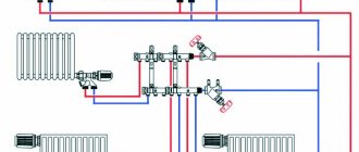
The layout of this apartment provides the opportunity to create one single heating branch passing through the kitchen, bedroom and living room, which will ensure an average temperature of 20-22⁰C in the rooms (+)
What about the environment? The apartment is located in a house located in the middle of a microdistrict of a small town. The city is located in a certain lowland, the altitude above sea level is 130-150 m. The climate is moderate continental with cool winters and fairly warm summers.
Average annual temperature is +7.6°C. The average temperature in January is -6.6°C, in July +18.7°C. Wind - 3.5 m/s, average air humidity - 74%, precipitation 569 mm.
Analyzing the climatic conditions of the region, it should be noted that we are dealing with a wide range of temperatures, which in turn affects the special requirement for adjusting the heating system of the apartment.
Calculation of local resistances
Local resistances arise in the pipe and fittings. The value of these indicators is influenced by:
- roughness of the inner surface of the pipe;
- the presence of areas of expansion or contraction of the internal diameter of the pipeline;
- turns;
- length;
- the presence of tees, ball valves, balancing devices and their number.
The resistance is calculated for each section, which is characterized by a constant diameter and constant coolant flow (in accordance with the heat balance of the room).
Initial data for calculation:
- length of the design section – l, m;
- pipe diameter – d, mm;
- specified coolant speed – u, mm;
- characteristics of control valves provided by the manufacturer;
- friction coefficient (depending on the pipe material), λ;
- friction losses – ∆Pl, Pa;
- coolant density (calculated) – ρ = 971.8 kg/m3;
- pipe wall thickness – dн x δ, mm;
- equivalent pipe roughness – ke, mm.
Hydraulic resistance - ∆P on a network section is calculated using the Darcy-Weisbach formula.
The symbol ξ in the formula means the local resistance coefficient.
If there is a stove in the house, it can only heat a small room. The installation of heating radiators in a large private house is mandatory, since otherwise the rooms distant from the stove will not be heated.
The main characteristics of the Buderus gas boiler are presented in this review.
We will tell you how to start a gas boiler in this article.
Heat generator power
One of the main components of the heating system is the boiler: electric, gas, combined – it doesn’t matter at this stage. Because its main characteristic is important to us - power, that is, the amount of energy per unit of time that will be spent on heating.
The power of the boiler itself is determined by the formula below:
Wboiler = (Sroom*Wshare) / 10,
Where:
- Sroom – the sum of the areas of all rooms that require heating;
- Wdel – specific power taking into account the climatic conditions of the location (this is why it was necessary to know the climate of the region).
Typically, for different climatic zones we have the following data:
- northern regions – 1.5 – 2 kW/m2;
- central zone – 1 – 1.5 kW/m2;
- southern regions – 0.6 – 1 kW/m2.
These figures are quite arbitrary, but nevertheless provide a clear numerical answer regarding the influence of the environment on the apartment heating system.
This map shows climate zones with different temperature regimes. The location of the housing relative to the zone determines how much energy needs to be spent on heating a square meter of kWatt of energy (+)
The amount of the apartment area that needs to be heated is equal to the total area of the apartment and is equal, that is, 65.54-1.80-6.03 = 57.71 m2 (minus the balcony). The specific boiler power for the central region with cold winters is 1.4 kW/m2. Thus, in our example, the calculated power of the heating boiler is equivalent to 8.08 kW.
Calculation of water volume and capacity of the expansion tank
The volume of the expansion tank must be equal to 1/10 of the total volume of liquid.
To calculate the performance characteristics of the expansion tank, which is mandatory for any closed-type heating system, you will need to understand the phenomenon of increasing the volume of liquid in it. This indicator is assessed taking into account changes in basic operating characteristics, including fluctuations in its temperature. In this case, it varies over a very wide range - from room temperature +20 degrees and up to operating values within 50-80 degrees.
It will be possible to calculate the volume of the expansion tank without unnecessary problems if you use a rough estimate proven in practice. It is based on equipment operating experience, according to which the volume of the expansion tank is approximately one tenth of the total amount of coolant circulating in the system
In this case, all its elements are taken into account, including heating radiators (batteries), as well as the water jacket of the boiler unit. To determine the exact value of the required indicator, you will need to take the passport of the equipment being used and find in it items relating to the capacity of the batteries and the working tank of the boiler
Once they are determined, it is not difficult to find excess coolant in the system. To do this, first calculate the cross-sectional area of polypropylene pipes, and then multiply the resulting value by the length of the pipeline. After summing up all branches of the heating system, the figures for radiators and boiler taken from the passport are added to them. One tenth is then subtracted from the total amount.
Dynamic parameters of the coolant
We move on to the next stage of calculations - analysis of coolant consumption. In most cases, the heating system of an apartment differs from other systems - this is due to the number of heating panels and the length of the pipeline. Pressure is used as an additional “driving force” for flow vertically through the system.
In private one- and multi-story buildings, old panel apartment buildings, high-pressure heating systems are used, which makes it possible to transport the heat-releasing substance to all sections of the branched, multi-ring heating system and raise water to the entire height (up to the 14th floor) of the building.
On the contrary, an ordinary 2- or 3-room apartment with autonomous heating does not have such a variety of rings and branches of the system; it includes no more than three circuits.
This means that the coolant is transported using the natural process of water flow. But you can also use circulation pumps; heating is provided by a gas/electric boiler.
We recommend using a circulation pump for heating rooms larger than 100 m2. The pump can be installed either before or after the boiler, but usually it is installed on the “return” - lower fluid temperature, less airiness, longer pump life
Specialists in the field of design and installation of heating systems define two main approaches in terms of calculating the volume of coolant:
- According to the actual capacity of the system. Without exception, all volumes of cavities where the flow of hot water will flow are summed up: the sum of individual sections of pipes, sections of radiators, etc. But this is a rather labor-intensive option.
- According to boiler power. Here the opinions of experts differ greatly, some say 10, others 15 liters per unit of boiler power.
From a pragmatic point of view, you need to take into account the fact that probably the heating system will not only supply hot water for the room, but also heat water for the bath/shower, washbasin, sink and dryer, and maybe for a hydromassage or jacuzzi. This option is simpler.
Therefore, in this case, we recommend setting 13.5 liters per unit of power. Multiplying this number by the boiler power (8.08 kW) we obtain the estimated volume of water mass - 109.08 liters.
The calculated coolant velocity in the system is precisely the parameter that allows you to select a certain pipe diameter for the heating system.
It is calculated using the following formula:
V = (0.86*W*k)/t-to,
Where:
- W – boiler power;
- t – temperature of the supplied water;
- to – water temperature in the return circuit;
- k – boiler efficiency (0.95 for a gas boiler).
Substituting the calculated data into the formula, we have: (0.86 * 8080 * 0.95)/80-60 = 6601.36/20 = 330 kg/h. Thus, in one hour, 330 liters of coolant (water) move through the system, and the system capacity is about 110 liters.
Pipe diameter calculation
Calculation of pipe cross-sections should be based on the results of thermal calculations that are economically justified:
- for a two-pipe system - the difference between tr (hot coolant) and to (cooled - return);
- for single-pipe – coolant flow G, kg/h.
In addition, the calculation must take into account the speed of movement of the working fluid (coolant) - V. Its optimal value is in the range of 0.3-0.7 m/s. The speed is inversely proportional to the internal diameter of the pipe.
When the water speed is 0.6 m/s, characteristic noise appears in the system, but if it is less than 0.2 m/s, there is a risk of air jams.
For calculations, one more speed characteristic will be required - the heat flow rate. It is designated by the letter Q, measured in watts and expressed as the amount of heat transferred per unit time
Q (W) = W (J)/t (s)
In addition to the above initial data, the calculation will require the parameters of the heating system - the length of each section, indicating the devices connected to it. For convenience, these data can be summarized in a table, an example of which is given below.
Table of plot parameters
| Site designation | Section length in meters | Number of devices in the area, pcs. |
| 1-2 | 1,8 | 1 |
| 2-3 | 3,0 | 1 |
| 3-4 | 2,8 | 2 |
| 4-5 | 2,9 | 2 |
Calculating pipe diameters is quite complex, so it’s easier to use reference tables. They can be found on the websites of pipe manufacturers, in SNiP or specialized literature.
When selecting pipe diameters, installers use a rule derived from an analysis of a large number of heating systems. True, this only applies to small private houses and apartments. Almost all heating boilers are equipped with ¾ and ½ inch supply and return pipes. This pipe is used for wiring up to the first branch. Next, at each section, the pipe size is reduced by one step.
This approach does not justify itself if the house has two or more floors. In this case, you have to make a full calculation and refer to the tables.