The use of heat accumulators for the heating system allows optimizing the combustion of solid fuels in boilers. In simple words, if there is a buffer tank - a heat accumulator - the homeowner does not need to visit the boiler room often, and the firewood will burn in an optimal manner. But for this, the container needs to be selected correctly, and then connected to the heating equipment, which will certainly cause difficulties for an ignorant person. Therefore, it is worth understanding in detail what a heat accumulator for a solid fuel boiler is, how to select it and connect it to the heating of a private house.
What is buffer capacity
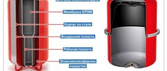
In fact, a heat accumulator intended for a heating system is an ordinary metal tank of rated capacity, covered with a thermal insulation layer. In the simplest factory-made models there are only pipes for connecting the coolant and sleeves for installing thermometers. In more expensive buffer tanks, thermometers are already built-in, and the most expensive products are equipped with heat exchangers in the form of coils. The structure of such a heat accumulator is shown in the figure:
As you can see, the design of the buffer tank is not particularly complex, which is why various craftsmen have adapted to making it with their own hands, which is discussed in a separate topic.
The purpose of the coils is to heat water to provide hot water supply and connect alternative sources of thermal energy - solar collectors. It is clear that this function is in demand only under favorable weather conditions in the region of residence. In general, the buffer tank for a heating boiler is designed to solve the following problems:
- Creating conditions for the operation of a TT boiler with maximum efficiency and minimal emissions into the atmosphere.
- Comfortable operation of the heat generator, when you do not need to add firewood to the firebox every 4-6 hours, including at night.
- Heating and supply of drinking quality water to 1-2 consumers (optional).
Most manufacturers of heating equipment operating on solid fuel indicate in the accompanying documentation that it is highly desirable to connect a heat accumulator to the TT boiler. The reason is this: the unit achieves its greatest efficiency when the operating mode is close to the maximum. And since the excess heat generated needs to be placed somewhere before being supplied to the heating system, you will need a buffer tank with water.
Without a thermal accumulator, we try in every possible way to “strangle” the thermal unit, limiting the supply of air for combustion. Not only does this reduce its efficiency to 40% (like a potbelly stove), but it also causes the release of toxic carbon monoxide into the atmosphere. Because of this, some European countries have banned the burning of wood and coal in heating boilers without a buffer tank.
With more rare visits to the furnace room, everything is clear: the heat accumulated in the tank will be spent on heating the house for a long time, provided that its volume is correctly calculated. In addition, when a solid fuel boiler works together with a heat accumulator, the likelihood of overheating and boiling of water in the unit jacket is reduced to almost zero.
In addition to interacting with wood heat generators, heat accumulators can also be used with electric boilers. This makes sense when the electricity consumed at night is calculated at a tariff that is 2-3 times lower than usual. During the period of time that this tariff is in effect, the electrical installation will be able to fully “charge” the thermal accumulator, and it will begin to release this energy to heat the house during the day.
With this option, the results of the previous calculation of the power of the electric boiler will have to be doubled so that its heat transfer is sufficient to heat the house and load the tank at the night rate.
What is a heat accumulator (buffer tank) and its purpose.
The purpose of a heat accumulator (TA) will be easier to describe using several example problems.
Task one. The heating system is based on a solid fuel boiler. There is no way to constantly monitor the temperature of the coolant in the supply and add firewood in a timely manner, as a result of which the supply temperature either exceeds what we need or drops below normal. How to ensure that the required coolant temperature is maintained?
Task two. The house is heated by an electric boiler. Electricity supply is two-tariff. How to reduce energy costs by reducing energy consumption during the day and increasing it at night?
Task three. There is a heating system in which heat is generated by heat generators running on various types of fuel and energy - e.g. gas, electricity, solar energy (solar collectors), earth energy (heat pump). How to ensure their efficient operation without loss of generated heat when there is no need for it, while at the same time providing the house with heat during periods of peak energy consumption?
Without going too much into the theory of heat engineering, for all problems a solution suggests itself in the form of installing a buffer tank in the system, which would serve as a reservoir for the coolant and in which its temperature would be maintained at a given level. The heat accumulator is precisely such a buffer capacity. To solve these problems, the heat accumulator is usually connected “into the gap” of the system to form the boiler and heating circuits. A schematic diagram for connecting a heat accumulator to a heating system is shown in the figure below.
Rice. Schematic diagram of switching on a buffer tank (heat accumulator)
Various ways to connect a buffer tank to a heating system can be found in the article “Heat accumulator connection diagrams”.
Currently, heat accumulators are most often used in heating systems with solid fuel boilers. In these systems, the use of a heat accumulator makes it possible to load fuel less frequently and provide a comfortable supply of heat regardless of fluctuations in the coolant temperature at the boiler outlet. Often, buffer tanks are installed with electric boilers to save money due to a reduced night tariff and in combined systems with the simultaneous use of solid fuel and electric boilers. A heat accumulator (TA) can be useful in systems with gas boilers, especially when the minimum thermal power of the boiler exceeds the thermal load of the facility. Due to longer periods of “loading” the heat exchanger (heating the coolant), it is possible to avoid “clocking” the boiler.
In addition to being used as a buffer tank, the TA serves as a hydraulic separator. This property of a heat accumulator is especially in demand in systems with heat generators operating on different types of energy (including alternative). As a rule, these heat sources operate on special coolants that do not allow mixing with other types and require a unique temperature and hydraulic regime, often incompatible with the heating circuit modes (radiator, heated floor). For example, the temperature range of a heat pump is usually ~5°C, but in a heat distribution circuit the temperature range can be much larger (10-20°C). To separate the circuits, the heat accumulator can be equipped with additional built-in heat exchangers.
The main functions of a buffer tank (heat accumulator): - accumulation and maintenance of a reserve of thermal energy in the form of a certain volume of coolant at a given temperature with the possibility of its use at the required period of time or when the generation of heat by its main sources ceases; — organization of a heating system using several heat generators of different types, which operate with different temperature and hydraulic conditions and using different coolants, as well as in different time periods; — hydraulic separation of the circuits of heat generators and the heating circuit, coordination of temperature conditions in various circuits and creation of favorable conditions for the operation of equipment, in particular heating boilers, with maximum efficiency.
Calculation of buffer capacity
The main criterion by which a buffer tank for a solid fuel boiler is selected is its volume, determined by calculation. Its value depends on the following factors:
- heat load on the heating system of a private house;
- heating boiler power;
- expected duration of operation without the help of a heat source.
Before calculating the capacity of the heat accumulator, you need to clarify all the listed points, starting with the average thermal power that the system consumes during the winter period. The maximum power should not be taken for calculation; this will lead to an increase in the size of the tank, and therefore to an increase in the cost of the product. It’s better to endure the inconvenience for a few days a year and load the firebox more often than to pay a crazy price for a large heat accumulator that will be used irrationally. And it will take up too much space.
Expert opinion. To provide thermal energy to a house with an area of 200 m², a buffer tank containing 1 ton of coolant, which is a volume of 1 m³, is sufficient. The statement is true for the central part of the Russian Federation; in more southern or northern regions the situation will be different.
Normal operation of a heating system with a heat accumulator is impossible when the heat source has a small power reserve. In this case, it will never be possible to “charge” the battery completely, since the heat generator must simultaneously heat the house and load the tank. Remember that the selection of a solid fuel boiler for connection with a heat accumulator assumes a double thermal power reserve.
It is proposed to study the calculation algorithm using the example of a house with an area of 200 m² with a boiler downtime of 8 hours. It is assumed that the water in the tank will heat up to 90 °C, and during heating operation it will cool down to 40 °C. To heat such an area in the coldest time, you will need 20 kW of heat, and its average consumption will be about 10 kW/h. This means that the battery must accumulate 10 kW/h x 8 hours = 80 kW of energy. Next, the volume of the heat accumulator for a solid fuel boiler is calculated using the formula for the heat capacity of water:
m = Q / 1.163 x Δt, where:
- Q is the estimated amount of thermal energy that needs to be accumulated, W;
- m – mass of water in the tank, kg;
- Δt – the difference between the initial and final temperatures of the coolant in the tank is 90 – 40 = 50 °C;
- 163 W/kg °C or 4.187 kJ/kg °C – specific heat capacity of water.
For the example under consideration, the mass of water in the heat accumulator will be:
m = 80000 / 1.163 x 50 = 1375 kg or 1.4 m³.
As you can see, as a result of calculations, the dimensions of the buffer capacity are larger than what the expert recommends. The reason is simple: inaccurate initial data were taken for the calculation. In practice, especially when the house is well insulated, the average heat consumption per area of 200 m² will be less than 10 kW/h. Hence the conclusion: in order to correctly calculate the dimensions of a heat accumulator for a solid fuel boiler, it is necessary to use more accurate initial data on heat consumption.
For reference. There is also an enlarged calculation method, according to which for each kW of boiler thermal power there is 25 liters of heat accumulator volume.
How to calculate volume without a calculator
Calculations are made based on residual energy. The basis is the boiler output per hour and energy consumption for heating. The difference between the temperature of the coolant supplied to the system and returned is also calculated.
The formula looks like this: m = Q / 1.163 x Δt,
Where:
- Q is the estimated amount of thermal energy that we can accumulate. This is the difference between the power generated by the boiler and what we need for heating;
- m – mass of water in the tank, kg. We want to calculate it;
- Δt – difference between the initial and final temperatures of the coolant, °C;
- 1.163 kW/kg – specific heat capacity of water.
Selection of heat accumulator
The remaining criteria for choosing a container are not so important and mainly relate to different options. One of them is a built-in coil that heats water for household needs. It may be useful if there are no other means of heating, but for high costs in the DHW network this method is definitely not suitable. In addition, the heat exchanger will take away part of the “charge” of the heat accumulator, reducing the autonomous operation time of the heating.
A useful option is a heating element built into the top of the tank, capable of maintaining the temperature of the coolant at a certain level. Thanks to electric heating, the system will not defrost in the event of an accident and will even be able to heat the house for some time after the battery has been “discharged” and the boiler has not yet been started.
The second coil for connecting the solar system is useful only in the southern regions, where solar activity will allow the heat accumulator to be loaded. But what you should pay attention to when selecting is the operating pressure of the tank. It should be taken into account that most solid fuel boilers are designed for pressure in the jacket up to 3 Bar, which means that the buffer tank should easily withstand the same amount.
Connection diagrams
There are many ways to connect a solid fuel boiler with a heat accumulator and a heating system. But they are all derived from the basic circuit shown below. With its help, it is easy to understand how these units work in pairs, and then install everything yourself.
A heat source running on solid fuel has a traditional boiler circuit with a mixing unit, whose task is to prevent the supply of cold coolant to the boiler. Then the supply and return pipelines are connected to the buffer tank, respectively, from above and below. In the same way, a heating system, also equipped with a mixing unit, is connected to the heat accumulator. Its purpose is to maintain the required water temperature in the system, adding part of the hot coolant if necessary.
Important point. The actual performance of the boiler circuit circulation pump should be slightly higher than that of the heating network pumping unit. Compliance with this condition will allow the flows inside the heat accumulator to move in the right direction (shown in the diagram with white arrows).
In fact, the network pump will be more powerful than the boiler pump and here's why. The resistance of the network of pipelines and radiators is higher than 3-5 m of pipe from the solid fuel boiler to the heat accumulator. The unit needs higher power and pressure to overcome this resistance. Therefore, a weaker boiler circuit pump can provide higher flow rates, you just need to configure both units correctly. There are 2 options to resolve the issue:
- When using 3-speed pumps, you can adjust their performance by switching speeds.
- Place a balancing valve at the inlet of the return from the system into the buffer tank, which can be used to make adjustments.
Simultaneous heating of heating devices and layer-by-layer loading of a heat accumulator is possible when the flows inside the tank move horizontally with a slight predominance from the side of the solid fuel boiler. The question arises - how to check this? The answer arises: thermometers must be installed at both return inlets to the tank (as in the diagram) and adjustments must be made by switching pump speeds or rotating the balancing valve. Important condition: the three-way valve of the heating network must be fully opened manually.
By adjusting it is necessary to ensure that the temperature at the inlet to the heat accumulator (T1) is less than at its outlet (T2). This means that part of the hot water goes to “charging” the battery. You can learn more about all the points from an expert by watching the video:
Alternative scheme
This scheme for connecting a buffer tank and a solid fuel boiler was proposed by one of the participants in the popular forum. Its peculiarity is that in the event of a power outage, the operability of the circuit remains, although you have to pay for this with increased diameters of steel pipes. The figure below shows the connection of a heat accumulator to a closed heating system, but during installation it is better to make it open, as the author himself says.
Briefly, the essence is this: thanks to the T-shaped input on top of the tank, the radiators are simultaneously heated and the thermal accumulator, made by hand, is “charged”. The boiler circuit pump is controlled by a clip-on sensor on the supply line, turning on the unit when it reaches a temperature of 60 °C. The circulation in the network depends on the room thermostat to which the network pump is connected.
Note. The proposed strapping scheme was tested by its creator from his own experience. All details of its installation and operation are described by the author on the forum