Characteristics of one-pipe and two-pipe systems
The water heating system can be single-pipe or double-pipe. Let's look at the features of each option.
In a single-pipe system, radiators are connected to the supply pipe in series. Its advantages include a simple design and low material consumption, since a minimum of pipes are required to be installed
. But when connected in series to heating devices remote from the boiler, the coolant enters already cooled, and in order to ensure the required level of heating of the air in the room, it is necessary to install radiators of higher power, which increases the cost of the project. Disadvantages also include:
- complexity of hydraulic calculation;
- limitation on the number of heating devices;
- the criticality of errors made at the design and installation stage;
- the inability to regulate the temperature of heating devices individually depending on the requirements for the microclimate of the premises;
- inability to shut off the flow of water to a separate radiator (for repair or replacement, etc.) without stopping the operation of the entire system;
- high heat loss.
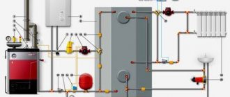
The diagram shows the difference between a one-pipe and two-pipe heating system
A 2-pipe heating system, unlike a single-pipe one, provides for a parallel arrangement of supply and return pipelines to which the radiators are connected
. This option has the following advantages:
- allows you to deliver liquid of the same temperature to all radiators (there is no need to increase the number of sections for batteries farthest from the boiler);
- a thermostat can be installed on each heating device;
- additional heating devices can be added to the installed line;
- there are no restrictions on the length of the contour.
Two-pipe heating also has some disadvantages, including the complexity of the connection diagram, increased consumption of materials and labor-intensive installation when compared with the single-pipe option.
It is also worth noting the radial (collector) connection of heating devices - separate supply and return pipes are installed for each radiator. The advantages of independently connecting heating devices include the maintainability of the system - disconnecting any of the circuits will not affect the performance of the remaining radiators. The main disadvantage is the need to lay a large number of pipes.
Typically, water heating of a private house comes down to installing a two-pipe system, since this is the most effective and cost-effective option.
List of equipment and parameters on the diagram
The heating diagram of any floor should indicate:
- Pipe distribution indicating all pipe diameters;
- Pipe insulation areas - length and thickness. Such thermal insulation is indicated graphically;
- Piping axes relative to zero level;
- Slope angles of bottlings;
- If there are gaps in the horizontal sections of the bottlings, then the dimensions of these sections are indicated;
- Supporting and hanging elements, compensators.
An example of markings on a heating diagram
- The remote shelf is used to identify shut-off valves, indicating their marking and type. Under the offset, the part designation is indicated according to the documentation (see figure above);
- Vertical horizontal piping with appropriate designations;
- All heating devices present in the circuit.
Mandatory requirement: it is necessary to indicate the type and main characteristics of these elements:
- How many sections does the heating radiator contain?
- How many sections or pipes are in the heating register, its diameter and total length;
- For other heating devices (convectors, radiators) – type of device;
- Designations of thermal installations (boilers, heating furnaces and heat exchangers, circulation and heat pumps, elevators, etc.);
- Mortgage equipment;
- Measuring instruments.
Heating diagram to scale
Heating equipment and calculations
All equipment used in the heating system is divided into auxiliary and main. The main one is a boiler or other heating device, the auxiliary one is radiators and distribution pipes with the accompanying fittings. To calculate the parameters of the required heating equipment, the specific power of the boiler is required, which varies depending on climatic zones:
- For regions of the Far North - 1.5-2.0 kW;
- For temperate climate zones and central regions - 1.2-1.5 kW;
- For southern zones - 0.7-0.9 kW.
Based on these amendments, the power of the heating device is calculated using the formula:
W boiler = S x W / 10;
Where W is the design power of the heating device (boiler, convector, etc.);
S – total area of the heated object.
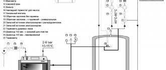
Axonometric diagram of boiler equipment with two burners
Pumps are either heat or circulation pumps. In most cases, except for low-rise buildings with natural coolant circulation, it is impossible to do without pumping equipment, so these devices are present in almost all diagrams. Pumps must meet certain technical requirements, including the following:
- Ease of installation, dismantling, ease of operation and maintenance;
- Low noise and economical device;
- Reliability and durability.
In low-rise residential buildings, three types of heating systems are used:
- The classic two-pipe scheme, according to which hot water is supplied through one pipe and returned through the second. In this scheme, the pump is mounted on the return line;
- Scheme with a vertical riser. In this scheme, hot water is also supplied to the radiators through one pipe and returned through the second, but a circulation pump is installed on the outlet pipe to supply hot coolant. Thus, hot water first passes through the upper radiators and then moves to the lower radiators of the system;
- The single-pipe scheme involves the movement of coolant sequentially from radiator to radiator with return to the boiler. This is the simplest scheme, but due to its low efficiency it is used in small one-story buildings.
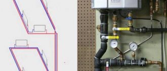
Simplified axonometric two-pipe diagram
Calculations when drawing up a heating scheme should take into account:
- Heat consumption in each room;
- Type and number of radiators;
- The number of risers, if any, as well as the total number of branches and circuits;
- Connection diagram for heating devices;
- Parameters of pipes and shut-off valves.
After completing the calculations of the heating system, they must be indicated on the diagram. The main purpose of an axonometric heating diagram is a graphical display of all parts and elements, but, in addition, the diagram must also display the technical characteristics of the heating equipment. The diagram must also include calculations for the heat supply to each room of the house, including utility rooms.
Types of two-pipe systems
Two-pipe systems are classified according to several criteria:
- direction of movement of the liquid medium (dead-end or flow);
- circuit type (open or closed);
- principle of fluid movement (natural or forced circulation).
Dead-end and flow-through
In a flow-type system, the direction of fluid movement in the supply and return pipes does not change. The dead-end circuit differs in that the coolant moves in opposite directions in the supply and discharge pipes. Radiators are mounted on the supply and return pipes after the bypass (jumper), which allows, if necessary, to turn off a separate heating device without disrupting the functioning of the entire heating circuit.
Dead-end and associated two-pipe system
Open and closed
The expansion tank (a container for compensating for thermal expansion) is an open tank or a sealed tank equipped with an elastic membrane. An open container is installed at the top point of the circuit; water must be added to it regularly. The membrane tank is designed to operate under pressure; its use reduces the risk of corrosion of metal elements, since the coolant does not come into contact with air.
Gravity and forced circulation
Gravity (with natural circulation) systems ensure the movement of coolant through pipes due to changes in the density of the liquid with increasing temperature and due to the action of gravity. To ensure effective circulation, it is necessary to correctly calculate the diameter of the pipes in all sections of the circuit and install them at a certain slope. Such a system usually includes an open expansion tank.
Forced circulation of liquid in the circuit is provided by a special pump. The energy-dependent system operates under increased pressure and requires the installation of a membrane tank and air vents. The popularity of this option is based on the high efficiency and ease of use of the system.
Forced circulation: gravity and pump
Installation algorithm
Installation of a two-pipe heating system, regardless of its characteristics, requires the use of the following tools, devices, materials and equipment
:
- tape measure, pencil/marker, building level, plumb line;
- electric drill;
- screwdriver;
- tool for pipeline installation (depending on the selected type of pipe);
- adjustable and gas wrenches;
- pipes (to choose from: metal-plastic, steel, copper, polypropylene);
- heating devices;
- air vents (manual for each battery, automatic for the entire circuit);
- expansion tank;
- boiler piping elements;
- drain valve and check valve for recharging the system, etc.
At the project preparation stage, it is necessary to perform a thermal calculation of the premises in order to determine the optimal power of heating devices. The type of radiators and pipes is also selected. Polypropylene is growing in popularity - such pipes do not corrode and do not overgrow, are suitable for hidden installation, are easy to install, and are affordable. The diameters of polypropylene pipes for a two-pipe system are determined depending on the thermal load and the length of the supply pipeline. The return line is mounted from pipes of the same section.
Definition
The term 'axonometry' comes from Greece and comes from two words: 'axis' and 'to measure'. The essence of the term is the graphic representation of three-dimensional objects by the method of projecting them onto a plane.
How to project an object:
- It is tied to three coordinate axes.
- The so-called picture plane is selected onto which the object is to be projected.
See: no coordinate axis should be parallel to it.
- All points of the object are projected onto the plane.
Because the picture plane is not parallel to any of the coordinate axes, along all axes the projection will have deviations from the actual sizes of the segments.
Depending on how the distortions are distributed along the axes, axonometry can be called:
- Isometric . In this case, the distortion on all axes is the same.
- Dimetric . The distortion is the same on both axes.
- Trimetric - all distortions have different values.
An axonometric diagram of a heating system is just its projection onto a plane that is not parallel to either the walls of the building or its floors. The projection indicates the elements of the system and their main parameters.
Rules and regulations for drawing up an axonometric diagram
Any as-built documentation, including drawings, is carried out according to a certain algorithm, using symbols and design rules. The axonometric diagram of heating, air conditioning and ventilation is no exception. Designers, if they do not use a computer program where all the data is already available, use several documents:
- GOST 21.206-93 SPDS;
- GOST 21.602-2003 SPDS.
Information for calculating the power of the ventilation system and other technical data are specified in SNiPs and GOSTs. From there such important parameters as the frequency of air exchange, standard values of temperature and humidity are taken. The composition and complexity of the axonometric diagram depend on them.
Rules
A complex version of the axonometric diagram.
The axonometric diagram is made in two types: a sketch and a full-fledged drawing. There are few requirements for the sketch; it is not an official document. A full-fledged axonometric drawing is performed according to all the rules prescribed in state standards:
- Selecting a viewing angle. The designer's primary task is to find the optimal point. A floor plan is used for this. It is positioned so that the lower part is adjacent to the designer, the left hand looks at the first axis of the building, the right hand looks at the last axis. The facade, which is closer to the designer, or rather its left corner, is the starting point for the axonometric diagram.
- Determining the orientation of duct lines. Everything is simple here. Ventilation ducts running parallel to the wall of the building closest or farthest to us are drawn as a horizontal line parallel to the walls. Bends running perpendicular to our wall are drawn at an angle of 450 to the horizontal line. Vertical sections of the ventilation system are drawn vertically.
- Scaling. An axonometric diagram, with the exception of a handwritten sketch, is carried out to a certain scale. It does not change within one drawing. If the axonometry to scale does not fit on the sheet, then breaks are allowed (this is when the duct line in the drawing is broken using a dotted line).
Requirements
The axonometric diagram, like other parts of the ventilation project, is carried out in accordance with the requirements of state standards:
- Extension lines for air ducts. With their help, the geometric characteristics, shape, and power of each channel are shown. A footnote with a shelf is set aside from each duct. Above the shelf the section size, length, width, or diameter (in the case of a round channel) is indicated. Below the shelf is the power value in cubic meters.
- Height marks are drawn on the right or left side of the drawing. This is necessary for the correct orientation of the system in the building. The first mark corresponds to the level of the clean floor; all the others “dance” from it. Heights are indicated in millimeters. If the duct has a round cross-section, then it is anchored from the center of the section; if it is square or rectangular, then from the bottom edge.
- All equipment, including fans, fittings, heaters, recuperators, is indicated by symbols or in the form of outlines.
- Often, an axonometric diagram shows the outline of equipment. This is done in the case of using local ventilation with individual suction or umbrellas. Equipment may be designated by an outline with a leader and markings.
- Inspection hatches are marked on the diagram. They are tied to dimensional lines. A callout is drawn above each hatch, similar to air ducts. The brand of the product is indicated above the shelf, under its number in the design documentation.
- All additional equipment, sensors, and metering devices are included in the drawing. Conventions are used.
- The drawing indicates sections of air ducts with insulation or treated with a fire retardant compound.
- Complex ventilation systems on large construction sites run through the entire building. Places of transition through load-bearing walls, partitions, and floor slabs are marked. Each overlap is marked. The walls are marked using the building axes.
- Air ducts are marked. The supply ones are designated by the letter - P, the exhaust ones - V. After the letter there is a number indicating the serial number of the branch. Within one drawing there can be P1 and B1, that is, the numbers for supply and exhaust are duplicated.
- Fans are marked according to the lines on which they are installed.
- Scale designation. Axonometric diagrams are scaled. This must be indicated on the drawing. For example, 1:50, 1:100. Means that one dimensional unit in the drawing corresponds to 50 or 100 units in reality.
Both simple and complex
Everything complex individually is very simple.
Without prevarication, I would like to note that for all the apparent simplicity of this event, the axonometric heating diagram is not exactly a simple thing. Here it is necessary to take into account a lot of factors, and some must be calculated. Therefore, immediately the first piece of advice.
Therefore, before drawing the entire system on paper or in a computer image, let's do some calculations.
Let's start with boilers
This is where it all begins.
It’s no secret that no matter how beautifully advertising describes all the delights of this or that heating equipment, there are main heating devices and auxiliary ones. Of course, you can’t heat a house with oil heating radiators, and heated floors are considered more in terms of comfort than heating a home, so we focus on the boiler, the heart of the home heating system.
And let's start considering the calculations with the already calculated coefficients for different climatic zones.
The specific design power of the boiler W will be:
- For regions of the far north and equivalent areas – 1.5 – 2.0 kW;
- For areas with a temperate climate and central regions – 1.2 – 1.5 kW;
- For southern regions – 0.7 – 0.9 kW.
Based on these coefficients, it is already possible to calculate the boiler power using a fairly simple formula: W boiler = S*W / 10, where W is the design power indicated above, and S is the total area of the room in your home.
A few words about pumps
We tell them about pumps, and they tell us about circuits.
In boilers and heating systems, these indispensable helpers will definitely have their say; it is with their help that all circulating fluid is pumped through the system. Is it possible to do without them? In principle, it is possible if the house is one-story, with a small total area (saving on pumps is more typical for systems of small country houses). For everyone else, pumps are required.
Moreover, modern pumps have a number of mandatory requirements, namely:
- Pumps must be easy to operate, as well as easy to install and, if necessary, dismantle;
- An important factor is noiselessness;
- These products must consume a minimum amount of electricity;
- Pumps must be reliable with a long service life.
When making calculations, pay attention
By and large, we pay attention to everything. But now the most interesting part begins, because the most painstaking
These works require very careful calculations before the entire scheme is put on paper.
But now the most interesting part begins, because it’s the most painstaking part. These works require very careful calculations before the entire scheme falls on paper.
An axonometric diagram of the heating system will be drawn up based on:
- Determining the heat demand of each heated room;
- Determining the number and types of radiators for heating and after fitting them into real conditions, and then into the diagram;
- Decisions regarding the entire heating system, which includes the presence or absence of risers, calculation of the number of required branches and circuits, the order of connecting heaters (radiator batteries);
- Carrying out calculations for pipes, namely: diameter, quantity, shut-off valves, thermostats, pressure regulators in the system (if they are not provided in the boiler);
- After all calculations have been carried out, the data is transferred to the diagram. In addition to the graphical representation, this diagram also indicates the technical characteristics of boilers, pumps, pipes, radiators, as well as all calculations for heating each room.
Heating systems
Different systems - different graphics.
In private houses there can be three heating systems:
- The heating system is two-pipe. This is a classic system in which hot water is supplied through one pipe, and waste (cooled water) is returned to the boiler through a common return. In this case, the pump is installed on the return pipe;
- Vertical heating system. This system is not much different from the previous one, the pump is installed in the outlet pipe and accelerates hot water, the heat first enters the upper levels and then passes to the lower levels;
Single pipe heating system. In this scheme, the heater passes from one battery to another and returns to the boiler; the scheme is typical for one-story buildings.
Features of drawings
When drawing up an axonometric diagram, pay attention to the following points:
- Plumbing and other fixtures connected to risers and the distribution network are reflected only when the necessary diagrams are not included in the attached documentation.
- The zero mark (first floor level) is shown on the risers by drawing a thin horizontal line. In the case of detailing the project, each of the nodes of the drawing is considered separately, reflecting it on an enlarged scale.
- If necessary, symbols of shut-off and control valves, watering taps and other system elements are added to sketches of diagrams and drawings of water supply networks and sewerage systems.
Axonometry of water supply, heating, sewerage
According to GOST 2.317-2011, all axonometric diagrams related to sanitary systems of water supply, sewerage, and heating are constructed in frontal dimetric (oblique) isometry with a left coordinate system.
Accordingly, the dimensions along the z and x axes will be without distortion, and the dimensions along the y axis will be two times smaller.
You may ask, what does this drawing have to do with pipes and plumbing installation? Now imagine that the planes along the axonometric axes are the walls of your house or apartment. Plumbing pipes, water supply routes, sewerage and heating pipes run along the walls, vertically or horizontally. This means we can draw pipe routes in axonometry without showing the walls themselves.
This will give very clear drawings of how and where the plumbing wiring needs to be installed. Moreover, plumbing fixtures are marked on the axonometric diagram with symbols, pipe diameters are marked, explanations are made, and tables on materials and equipment are compiled for the diagrams. As a result, you have in your hands a detailed guide on how to install plumbing in a house (apartment), virtually eliminating installation errors.
Heating axonometry: what to pay attention to?
After completing the proper thermal calculations of the heating system, the data is transferred to an axonometric diagram. In the process of performing axonometry, the primary circulation circuit of the hot coolant is determined - from the final heating point to the boiler unit and back.
In the axonometric heating diagram, it is necessary to pay attention and indicate the following important points:
- Perform the correct orientation of the system on the site. The main elevation starts at the floor level, from which all other elevations for multi-story building plans go.
- Extension lines for pipes are drawn, which indicate the geometric and thermal characteristics of each branch. To do this, a footnote is created with a shelf above which all required data is indicated.
- Elements of the circuit equipment with symbols are applied. A callout is drawn above each element, similar to pipelines. Above the shelf is the equipment brand and its project number.
- They indicate places where pipes pass through load-bearing walls or other structural barriers. Each crossing is marked and walls are marked using building centerlines.
- Set the scale, for example, 1:30, 1:50. It means that one dimensional unit in the sketch corresponds to 30 or 50 real units.
Axonometric diagram of a house's water supply system
For example, two axonometric diagrams of a water supply system. These are two bathrooms, with a manifold circuit and installation of a boiler in one of the bathrooms.
Other schemes in articles:
- Apartment water supply schemes using metal-polymer pipes
- Installation diagram of apartment water supply, collector wiring
Features of sketch design
Here attention is focused on the reflection of instruments. If one element climbs onto another, and this happens in most cases, then a dotted line is drawn indicating the displacement of the plumbing element for the purpose of a better visual effect.
The axonometric diagram of the water supply system must include readings of all pipe diameters. If the toilet bowl is not marked on the outlet, then take a diameter of 50 mm; if there is one, the minimum diameter should be 100 mm. These numbers are important to remember. For risers, in 90% of cases, a figure of 100 mm is used. Slopes in a similar diameter will be equal to 0.02; with an indicator of 50 mm, the slope angle is set to 0.03.
If you have already applied all the elements, mark the outlets whose diameter is larger than that of the risers; the slope is taken to be 0.02.
At the last stage of drawing up the axonometry, special notes are made based on the characteristics of the site and the construction plan. Here they note the level of soil freezing, the location of the foundation, as well as other factors that influence the corrections.
Treatment plants
Various devices can be used as treatment facilities:
- cesspool;
- septic tank;
- biological treatment station.
Each device has its own positive and negative qualities. A cesspool is better suited for small houses or cottages where people appear seasonally. Biological treatment stations are quite expensive, but demonstrate very good performance. A septic tank is an optimal design that can be made with your own hands or purchased ready-made.
Heating systems: diagrams and drawings
The drawings of the heating system will form the basis for drawing up cost estimates, selecting equipment and components, and they will also be used to carry out installation work of the heating system.
In order for the drawings to be accessible and understandable to the performers, the elements of the circuit are marked on them in accordance with the existing standard symbols and markings:
- T1 – boiler supply pipeline;
- T2 – boiler return pipeline;
- T11 - supply pipeline of the heating system;
- T21 – return pipeline of the heating system;
- St - heating system riser;
- GST - main riser of the heating system;
- B1 - cold water;
- T3 – hot water supply pipeline;
- T4 – DHW circulation pipeline;
- A- ventilation systems;
- G- gas supply systems.
Axonometric diagram of a heating system with bottom wiring
The operating principle of a heating system with bottom wiring is to supply coolant to the heating devices through a pipeline located below the level of the radiators. The heated water is supplied to the intra-house heating pipeline under pressure created by the circulation pump. Next, the hot water passes through the heating device, releases its heat into the room and returns through the return pipeline to the heat supply source for the next heating cycle. If this system operates without a pump, that is, operates on the basis of natural circulation, then in a private house it will be necessary to install a boiler below the level of the heating devices.
For an axonometric diagram of the heating system of such a system, the levels of equipment location must be indicated, as well as the minimum slopes of pipelines, installation points for air vents and Mayevsky taps, since such a system is prone to airing. In addition, the ACO must clarify the design features of the system with bottom wiring: one-pipe or two-pipe. Since these options have their own characteristics and differ in the amount of additional equipment required.
Axonometric heating diagram with top wiring
This heating system is structurally distinguished from the scheme with bottom wiring by the location of the pipes for the supply coolant. They are located in the upper part of the room under the ceiling or in the attic of a one-story building. This scheme is used in cases where it is impossible to implement lower wiring due to the actual levels of the location of the heating source and batteries.
A two-pipe scheme with top wiring is most optimal when using the natural movement of the coolant, when good water pressure is provided, created by the difference between the lower and upper heating points.
An axonometric heating diagram with top wiring should include on the graphic document:
- Adapted installation of pipeline systems: directly under the ceiling or in the attic, at the same time it is necessary to take into account the position of furnishings so that they do not cover pipelines and shut-off valves.
- A minimum number of branches and turns in order to create optimal hydrodynamic characteristics of the system.
- Take into account the increase in coolant volume, which should be ensured by choosing a boiler with high power parameters.
Legend
Heating axonometry is compiled according to estimate calculations, determined taking into account climatic features, thermal insulation characteristics of the structure, the type of equipment used and other components included in the heat supply system. Based on this data, installation occurs.
Conventions used in drawings and sketches Source pechiexpert.ru
The heating circuit is equipped with the following symbols:
- T1 – supply pipeline line to the heating boiler.
- T2 – return branch from the heating boiler.
- T11 – supply line of the heating system pipeline.
- T21 – return branch of the heating system.
- St – heating system riser.
- GST is the main riser of the heating system.
- B1 – cold water supply.
- T3 – pipeline line with hot water supply.
- T4 – hot water circulation pipeline line.
- A – ventilation system pipeline.
- G – gas supply branch of the pipeline.
Two-pipe heating system diagram Source rezkadecor.ru
What should be displayed
The axonometry of the water supply and heating system reflects all the maximum information regarding the pipeline. In particular, it displays:
- Existing pipelines and their diameter.
- Places where additional thermal insulation is required.
- The level of the axes of each pipeline, marked relative to the zero mark, the value of which is indicated in the description.
- Number and location of supports, compensators, suspensions. Information about them is written in the take-out shelf, under which you should specify the type of fragment being described. Here you will also be informed about the document corresponding to this element.
- Spill slope (if their presence is required according to technical conditions. For example, in a gravity system or cottages with top pouring).
Important! If there are one or more spills on a horizontal bottling area, their size must be indicated.
Indication of the direction of movement and slope of filling in a home heating system Source www.tproekt.com
In addition to the above, the heating axonometry should contain information about the following system components:
- Type of installed shut-off valves. Information about taps and valves is indicated in the take-out shelf, under which a clarifying entry is made. At the bottom is the element number according to the operational catalog.
- Risers and benches are indicated if there are horizontal sections. It is also indicated with detailed operational designations.
- Characteristics, location and number of radiators, convectors and other heating devices.
Types of radiators for water heating systems Source greypey.ru
In relation to the above-mentioned heating devices, it is necessary to indicate their main characteristics and their type:
- All data by sections.
- Heat transfer coefficient in sectional radiators, material.
- Data on finned radiators.
Healthy! Regarding other, non-standard heating elements, when drawing up a heating axonometry, their heat transfer coefficient and a detailed description should be indicated.
Types of boilers for heating a cottage Source www.gazekoset.ru
Required final elements:
- Any heating installations (elevator units, circulation pumps, boilers, furnaces with heat exchangers, heat pumps).
- Embedded devices, which include oil cups used to control temperature, as well as taps and control valves installed in them, used to measure pressure in the heating system.
- Devices that are entrusted with the function of measuring the value of the heat transfer coefficient of a heating system.
Important! All of the above is noted in the schematic representation strictly in the designations assigned to them.
Record order
The above-mentioned standards prescribe the order in which axonometric information about the heating system should be entered. The order of listing the elements is as follows:
- The first column indicates the heating units (boiler, radiator, stove).
- In the second - shut-off and control valves (valves, cocks, throttles, plugs, valves).
- Next - other parts of the heating system (discharges, mud storages, settling tanks, expanders).
- Next, the heating axonometry indicates structures that operate on the embedded principle. These include oil cups, as well as bends in which control valves are installed.
- Then the characteristics of the pipelines are indicated with a separate specification for each diameter. The presence of bends, flanges, crosspieces for welding and bolts is not indicated.
- The last item in the description includes information about the thermal insulation used (name, characteristics).
Real elevator unit in the basement of a typical high-rise building Source www.tproekt.com
Interesting! In fact, in apartment buildings, mortgage pockets remain empty. Thermometers and pressure gauges installed in them are removed after a trial run of the system. The reason for dismantling is related to poorly closing utility room doors and the high cost of measuring equipment.
Scaling Requirements
Depending on the complexity of an individual element, a remote diagram can be drawn up for it. For example, in relation to distribution units, the heating axonometry has a separate drawing, made on a scale of 1 to 50 or 1 to 100.
In this case, a value of 1 in 200 or 1 in 100 is used for the entire axonometric project. In order to obtain detailed images of individual fragments of the heating system, larger values are also used: 1 in 5, or 1 in 10.
Scale 1 to 10 on an axonometric drawing Source tauproekt.ru
Symbols of ventilation systems
Axonometry of ventilation must be performed in accordance with the accepted notation system. Otherwise, it will be impossible to read the drawing and understand which element the designer had in mind. This is especially true for complex branched circuits consisting of many heterogeneous elements.
Fan designation on the ventilation diagram
Fans are designated as a somewhat simplified image of the housing of a radial device - a cochlea.
Axial fans are depicted as a stylized image of an impeller (impeller) in a rectangle or circle:
It is noteworthy that the images on the inclined lines have corresponding shapes, emphasizing that the element belongs to this particular line of air channels. In different diagrams there are images with slight changes in appearance, but the general rules must be followed.
Air duct designation
Air ducts are indicated by a solid thick line. It is positioned horizontally for ducts running perpendicular to the direction of view, vertically for vertically located air ducts and at an angle of 45° for ducts parallel to the direction of view (going deep into the drawing). The dimensions of the channels - diameter for round channels or width-height for rectangular channels - are indicated by corresponding inscriptions on extension lines. Flexible ducts are depicted as a wavy (zigzag) line. Thermally insulated - a straight thick line with a thin zigzag line applied along the longitudinal axis.
Designation of the ventilation check valve in the diagram
Valves in the diagrams are indicated in the form of rectangles located vertically, with filling corresponding to the purpose of the device. The check valve has a wide diagonal stripe.
Valves for other purposes have their own types of filling. Thus, the fire arresting valve is completely filled with black, the smoke exhaust valve is designated as a rectangle, divided diagonally, with a lower black part, etc.
Diffuser designation on the diagram
Diffusers are schematically designated as a light triangle, with the tip directed in the direction of the air flow. At the same time, the designs and types of diffusers are very different, so the diagrams indicate a conventional device without reference to a specific type. The specifics of using diffusers allow this approach, since the main condition is only throughput.
Execution Rules
An example of a schematic diagram of a ventilation system.
Ventilation schemes are usually performed in a frontal isometric projection (axonometry). This design allows you to see the entire network of air ducts in three dimensions, because, unlike plans or sections of a building, a third axis appears in the axonometric coordinate system, on which height values are plotted. Modern design programs make it possible to quickly and efficiently create axonometric diagrams. But not everyone has access to these opportunities, and the result still needs to be received on paper. Therefore, such a diagram can be drawn by hand in the form of a sketch; the main thing is to follow a number of rules for making axonometric diagrams. By adhering to them, you will get a complete picture of the supply or exhaust system on paper.
You should start by choosing the direction of the viewing angle of the room or building in which the air ducts will be laid.
In accordance with the rules, you need to choose a viewing angle from the facade of the building that is located on the bottom of the layout; the outer wall of this facade is marked by the first letter axis. If you are drawing a simple sketch of one room, then you can do it as conveniently as possible, but you should remember that if the documentation is formalized, the drawing will have to be redone. The air ducts of the system are drawn in the form of solid thick lines according to the following principle:
- if the channel runs parallel to the façade selected for the viewing angle, it is drawn as a horizontal line;
- the air duct perpendicular to this facade is drawn on the diagram at an angle of 45 degrees to the horizontal while maintaining scale;
- vertical sections are made with vertical lines.
What should be visible as a result?
Figure 2, 3. Schemes of ventilation systems.
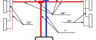
Figure 2 shows as an example an axonometric diagram of supply ventilation with mechanical stimulation. It shows at what marks the air ducts are laid and what diameters the dampers are installed to regulate the flow on each of the 4 branches. In front of them there are hatches for measuring air speed, and each branch ends with an air distribution device.
That is, this diagram contains all the necessary data for calculating or installing the system; ideally, each diagram should be drawn this way.
The second example in Figure 3 shows an exhaust ventilation system with local exhaust in the form of umbrellas and equipment for cleaning contaminated air (cyclone). From the drawings shown as examples, it is clear that the designations of the air ducts, if necessary and of high complexity, can be broken in order to move part of the diagram to the side. Then the places of breaks are marked in lowercase letters, and a thin dotted line is drawn between them. The axonometry is drawn in accordance with the scale; according to the standards, they can be taken as 1:50, 1:100; 1:200.
Axonometry of the heating system
Axonometry of heating
Schemes are drawn both for small private houses and for large industrial or public buildings. The design rules almost completely coincide with ventilation. Heating plans can be combined with ventilation and air conditioning; axonometry is performed separately. The rules are stated in GOST 21.602-2003 “Rules for the implementation of working documentation for heating, ventilation, air conditioning”:
- Drawing scale 1:50, 1:100, 1:200. If a sketch is made, it is selected individually. Individual elements and nodes are reduced by 1:10, 1:20, 1:50.
- If the length of the heating branch does not allow it to be included on the sheet at a given scale, then a break is indicated with a dotted line. The edges are marked with letters.
- All additional elements on the axonometric diagram are indicated by catchy signs. The use of contours is allowed.
Example of an axonometric diagram
Axonometry of a heating (heat supply) system includes:
- Pipelines with diameter indication and alphanumeric numbering.
- Pipeline installation height. Binding from the floor level of the first floor, basement or foundation.
- Direction and digital value of the slope.
- Dimensions of horizontal sections, only if there is a gap.
- Installation locations of shut-off valves with markings of each element.
- Pipe attachment points, indicating the type of fastener and document number.
- Vertical riser pipes. Marked as horizontal.
- Instruments for measuring pressure, temperature, counters.
- Heating radiators, their quantity, type and installation location.
This is not a complete set of requirements for axonometric diagrams of ventilation, heating and air conditioning. To avoid mistakes, calculate correctly and get a full-fledged project, high qualifications are required.
These are the kind of specialists who work here. Our organization operates in Moscow and the Moscow region, we also carry out orders from nearby regions and are considering options for remote cooperation. You will find ways to contact us on the “Contacts” page.