Tichelman loop for two floors or more
Most often, such a heating system is installed in one-story buildings with a large area. It is in such houses that it works most effectively. However, sometimes such a system is assembled in two or three-story buildings. When performing wiring in such houses, you should adhere to a certain technology. According to Tichelman’s scheme, in this case it is not each floor individually that is connected, but the entire building as a whole. That is, an equal sum of the lengths of the return and supply pipelines is maintained for each radiator in the house.
The Tichelman loop on two floors is thus assembled according to a special scheme. Experts also believe that using only one circulation pump in this case is inappropriate. If there is such a possibility, the building should install one such device on each floor. Otherwise, if a single pump breaks down, the heating will be turned off in the entire house at once.
Volume of water in the system
Of course, in order for the Tichelman loop heating system to work efficiently, before installing it, you should also calculate the required coolant flow. To determine this parameter, you must first calculate the heat loss of the building. This can be done using the formula G = S * 1 / Po * (Tv - Tn)k. Here Po is the heat transfer resistance, Tv and Tn are the air temperature outside and in the house, k is the reduction factor. The first and last indicators are determined from tables depending on the design features of the building. Actually, the coolant flow itself is calculated using the formula Q = G/(c*(T1-T2)), where:
- c is the specific heat capacity of water (4200),
- T1 is its return temperature,
- T2 - in the supply pipe.
The last two parameters are determined taking into account the nonlinearity of heat transfer from radiators. Ultimately, the difference between their values should be approximately 15-20 C.
Opinion of country house owners about the system
According to most owners of country real estate, this scheme is indeed very effective - the Tichelman loop. This system has received simply excellent reviews. If it is properly designed and assembled, a very comfortable microclimate is established in the house. At the same time, the system equipment itself rarely breaks down and lasts a long time.
Not only the owners of residential buildings, but also the owners of dachas speak well of the Tichelman loop. The heating system in such buildings is often used irregularly during the cold season. If the wiring is done according to a dead-end circuit, when the boiler is turned on, the rooms are heated extremely unevenly. With a passing system, such problems, of course, do not arise. But assembling heating according to such a scheme is really more expensive than using a dead-end one.
Installation features when balancing is needed
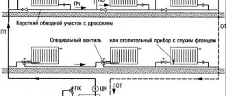
As already mentioned, the Tichelman loop does not require adjustment of the amount of coolant passing through the radiators. But only when radiators of the same power are installed in the building. However, in large houses such a heating system assembly scheme is rarely used. For example, weak radiators are usually installed in the boiler room and other utility rooms, while more powerful models are installed in living rooms. Of course, all these batteries will need different ducts. If the coolant flow is calculated for weak radiators, it will not be enough for powerful ones. With reverse circuits, hydraulic noise will begin to appear in small batteries. To prevent this from happening, balancing valves are installed.
Incidental heating scheme - device, application, how to do it
The associated heating pipeline wiring diagram is distinguished by the fact that it is self-regulating. If it is assembled correctly, then there is no need to adjust it after installation. Each radiator in this system must have the same pressure difference between supply and return. Each heating device in a parallel circuit operates under the same hydraulic conditions.
How does a ride work?
The same pressure difference on the radiators occurs because the sum of the supply and return lengths is the same for each. This can be clearly seen in the diagram. Take any battery from the system and estimate the total length of the supply and discharge pipelines to the boiler.
Those. all heating devices are in the same conditions automatically, and this is exactly what other schemes achieve through fine tuning and sometimes cannot achieve. For example, a beam circuit has a complex setup, where each battery is connected by a long pair of pipelines to one collector. The lengths of these pipelines are different, the radiators mutually influence each other, so the system must be carefully adjusted.
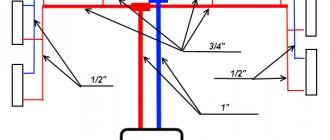
Pipe diameters
It is desirable that the diameter of the main pipeline (both supply and return) be the same throughout the entire ring, with the exception of connecting the last radiator. Where from the point of branching to the penultimate one, you can use a smaller diameter, because this will no longer be a main line, but a branch to the last heating device in the circuit. Those. the final section of both feed and return may have a smaller diameter.
Maintaining one significant diameter of the lines is necessary to ensure the same conditions for the radiators. Those. so that this “ride” would be a balanced system, where all batteries work stably under the same conditions.
If you start to “play” with savings and reduce the diameter of the line as the liquid moves (after all, less is required with each branch), then it is very easy to do, so that the group of last radiators will always be colder, i.e. The system will be difficult to configure.
Thus, for a small house with 6 - 8 radiators, a pipeline with a diameter of 26 mm is laid from the boiler (external for metal-plastic, for polypropylene and other materials - other values), then to the penultimate device - 16 mm. On the contrary, for the return line - from the first battery 16 mm, then from the second - a 26 mm ring to the boiler.
But this is just an example for a small system, and if the house is large, then the diameter of the pipelines may need to be larger, so that the pipeline does not make noise at the end sections, so that the speed in it does not exceed 0.7 m/s. The required diameter can be determined by a simple selection based on the connected power; an example of the calculation can also be found on this resource.
Do you always need a ride?
The associated heating system is more expensive than a dead-end heating system, by 20 percent. The cost overrun is associated with the use of large-diameter pipes, and especially their fittings - tees on the radiator branches and adapters to a smaller diameter to which the radiators are connected.
In a dead-end circuit, the diameters of the pipes will be smaller, since all the power is divided into 2 or more arms at the exit from the boiler.
Hiking becomes especially cumbersome when it is not possible to run pipes in a ring around the perimeter of the house - from the boiler outlet to its inlet. Then the return line has to be returned in the same way as the supply line.
The result is a complex loop of three main pipelines of great thickness. This should be avoided and the ride should be converted into a simpler dead-end scheme according to specific circumstances.
The usual transition to a dead-end system occurs when the number of radiators is reduced to 10 or less. Then it becomes possible to balance the radiators at dead ends and the shoulders themselves without significantly increasing the pump power.
With 3, 4 or even 5 radiators in an arm, there is no problem balancing all the radiators and arms in a dead-end heating circuit.
And if the same ten radiators have to be divided along the shoulders as 6 and 4, then it is better to make a self-adjusting ride, since with 6 heating devices and unequal dead ends, you will have to unnecessarily increase the pump power and “squeeze” the batteries located closer to it too much.
Complications when creating a secondary heating system and its configuration
If, as recommended, the diameter of the pipelines is the same, and the radiators are located at the same height level, and also if there is not too much difference in the power of the radiators, then there can be no problems with the operation of the system.
More precisely, any problems like “the 3rd radiator does not heat” arise only due to installation violations. For example, polypropylene was soldered with beads and overlap of the internal diameter.
But if the factors mentioned above that are negative for the operation of the system are present, then differences in the operation of the radiators may occur.
- The one located higher will take more coolant.
- Too powerful will not be able to develop it to the maximum, and when the pump flow increases, the smallest batteries will begin to make noise due to the high speed.
- Those connected with a reduced pipeline diameter (the latter does not count) most likely will not develop power, since the pressure on them will be less.
In general, the ride is a stable scheme, but “gentle” - you shouldn’t break the rules for its creation, and everything will work as expected.
The only question that remains is the combination of very powerful radiators with others, because if this is not solved, then the system will be... not applicable at all.
It is possible that in the greenhouse we will need one 5 kW heating device, and in the toilet - 0.5 kW. By adjusting the pump and pipelines for a 5-kilowatt unit, we will apply increased pressure to the battery in the toilet and increase the speed through it too much.
And the solution to the power conflict is the same as in the shoulder circuit - balancing valves. They should be placed at least on the lowest-power radiators in the driveway, protecting them from high pressure.
But if the radiators are controlled by local thermal heads, then a situation is possible when some of them turn off, and some that remain in operation begin to make noise due to the increased flow. Therefore, it is better to install balancing valves on all heating appliances at once when creating an associated heating scheme for a home.
One of the main questions remains: is it possible to assemble an associated heating system at home with your own hands? Of course you can. But you need to pay attention to mastering the following questions as well.
Selecting the type of pipes and their diameter, selecting radiators by power, boiler piping, radiator piping, correct selection of fittings, installation methods, techniques and problems with the selected pipeline, installation training. In principle, even beginners in plumbing could assemble excellent, functional heating systems from modern materials. It is likely that this will continue to be the case.
The procedure for performing installation work
The work consists of the following operations:
- Boiler installation. The required minimum room height for its placement is 2.5 m, the permissible volume of the room is 8 cubic meters. m. The required power of the equipment is determined by calculation (examples are given in special reference publications). Approximately for heating 10 square meters. m requires a power of 1 kW.
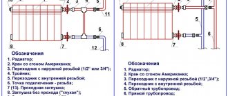
- Hangment of radiator sections. The use of biometric products in private homes is recommended. After selecting the required number of radiators, their location is marked (usually under window openings) and secured using special brackets.
- Extension of the associated heating system line. It is optimal to use metal-plastic pipes that successfully withstand high temperatures, are durable and easy to install. The main pipelines (supply and return) are from 20 to 26 mm and 16 mm for connecting radiators.
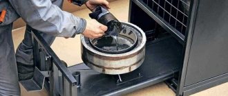
- Installation of a circulation pump. Mounted on the return pipe near the boiler. The insertion is carried out through a bypass with 3 taps. It is necessary to install a special filter in front of the pump, which will significantly increase the service life of the device.
- Installation of an expansion tank and elements ensuring the safe operation of the equipment. For a heating system with a passing coolant movement, only membrane expansion tanks are selected. Safety group elements are supplied with the boiler.
To line doorways with a main line in utility rooms and utility rooms, it is allowed to install pipes directly above the door. In this place, to prevent air accumulation, automatic air vents must be installed. In residential areas, pipes can be laid under a door in the body of the floor or bypassing an obstacle using a third pipe.
Tichelman’s scheme for two-story houses provides for a certain technology. Pipe distribution is carried out with tying the entire building, and not each floor separately. It is recommended to install one circulation pump on each floor, maintaining equal lengths of return and supply pipelines for each radiator separately in accordance with the basic conditions of the associated two-pipe heating system. If you install one pump, which is quite acceptable, then if it fails, the heating system in the entire building will shut down.
Many experts consider it expedient to install a common riser on two floors with separate piping on each floor. This will make it possible to take into account the difference in heat loss on each floor with the selection of pipe diameters and the number of required sections in radiator batteries.
A separate associated heating circuit on the floors will greatly simplify the setup of the system and allow for optimal balancing of the heating of the entire building. But to obtain the desired effect, it is necessary to insert a balancing crane into the travel circuit for each of the two floors. The taps can be placed side by side directly next to the boiler.
Associated heating system
Table of dependence of the internal diameter of the pipe on the thermal load
Table of dependence of the internal diameter of the pipe on the thermal load
The following guidelines can be taken into account:
- For heat losses of up to 15 kW (150 m² of area), pipes with a diameter of 20 mm are suitable.
- For losses from 15 to 27 kW (up to 250 m² of area), pipes with a diameter of at least 25 mm will be required.
Carrying out calculations using the given formulas or hydraulic tables is a difficult task for the homeowner, so you can rely on the recommended pipe diameters.
The following conditions must be met:
- Place pipes under the floor covering to avoid high-rise contours. If this is not possible, then you need to take into account the configuration of the house and strive as much as possible for the same height of pipe laying.
- Pipe material is metal-plastic or polypropylene reinforced with aluminum foil. Such pipes are stronger and will last a long time.
- Radiators are installed bimetallic or steel with a bottom connection system. Such batteries have higher hydraulic resistance, which balances the system. The power of the radiators should be the same throughout the entire area of the house.
- Each battery is equipped with a balancing valve on the return line. It is advisable to install thermostats.
Boiler installation
The room where the boiler is installed must have a height of at least 2.5 m. The volume of the room is recommended from 8 cubic meters. The hot water boiler must be selected depending on the area of the heated house. Boiler power for heating is 10 kW. m is equal to 1 kW. Based on this, the power for the entire system is selected.
The boiler piping consists of a set of shut-off valves; it is installed in several places:
- On the make-up pipe.
- On both sides of the pump.
- At the expansion tank.
- On the pipes coming from the boiler.
If you do the wiring yourself, without submitting it to supervisory organizations (and so far this is not required in our country), you can sculpt anything, guided, of course, by common sense.
Mainline pulling
When installing the associated heating system distribution line, the following must be taken into account:
- The outlet branch of the main line must be located below the supply branch.
- The heat supply and heat removal pipes must be parallel to each other.
- The expansion tank must be installed above the heating boiler.
- Valves for draining water must be installed on the connecting radiators. It is recommended to install a thermostatic head on each radiator to ensure a comfortable temperature.
- When laying the pipeline, right angles are excluded to avoid the occurrence of air locks in the system.
- The expansion tank must be installed in a heated room.
- All diameters of pipes, fittings and taps must match each other. You cannot install pipes of different diameters in an attempt to save money. The water pressure in the system will be disrupted.
Installing a circulation pump
It is not reasonable to rely on natural circulation, since there are 10 or more batteries in the associated heating system. Gravity will not be able to work without forced pressure. The circulation pump is installed on the return branch near the boiler. The pump is installed using a bypass and three valves. It is recommended to install a filter.
Installation of the Tichelman loop - useful tips
The layout of the rooms can complicate the assembly of such a system. For example, in any case, the highways will have to be pulled in the area of the door. In utility rooms, pipes may be laid above the opening. Indeed, in this case, special attention is usually not paid to the design of the room. In residential premises, the pipe is most often pulled under the door. To do this, you may need to perform a procedure such as punching a tie. If for some reason it is impossible to draw under the door, the return pipe returns to the same place where the supply came from. In this case, sections appear in the system where there are not two, but three pipes. This scheme is sometimes used in private homes. But assembling a heating system is expensive. Therefore, as mentioned above, in this case it is worth considering using a collector or dead-end circuit.
Do-it-yourself Tichelman loop
Piping for a Tichelman loop in a heating system
When installing such a structure yourself, you need to pay attention to the following points: the type and dimensions of the pipes used, the selection of the capacities of the components involved and their piping. It should also be taken into account that a configuration with height differences (with pipes laid above the doorway) requires air removal and drainage. Sometimes, instead of arranging such an installation, they opt for a dead-end circuit, characterized by a longer path length.
The supply contains components responsible for the safety of the system. They include a pressure gauge, a bleed valve and an automatic air release device. The open configuration involves vertical routing of the path before the start of evasion, with an expander placed at the highest point. The backbone is then routed to the remaining network components.
On the way back, a pump is installed, the power of which should be enough to neutralize the hydraulic resistance. The piping system for the boiler includes shut-off fittings mounted next to it on both pipes and near the expansion tank. They are also attached to the sides of the pump and to the feed pipe located near it.
Tichelman heating feature
The idea of changing the operating principle of the “return” was substantiated in 1901 by the German engineer Albert Tichelman, in whose honor it received its name - the “Tichelman loop”. The second name is “reversible type return system”. Since the movement of the coolant in both circuits, supply and return, is carried out in one, parallel direction, a third name is often used - “scheme with parallel movement of thermal fluids”.
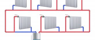
The essence of the idea is to have the same length of forward and return pipe sections connecting all radiator batteries with the boiler and pump, which creates the same hydraulic conditions in all heating devices. Circulation circuits of equal length create conditions for the hot coolant to travel the same path to the first and last radiator and receive the same thermal energy.
Tichelman loop diagram:
Associated heating system
Traditionally used diagrams of the associated heating system
Used diagrams for the associated heating system
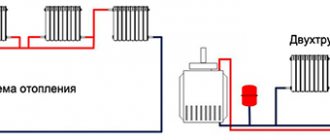
A two-pipe scheme (double-circuit) requires the installation of two circuits to circulate water from the boiler to the heating radiators. The first pipe supplies heat from the boiler to the radiators, the second is the return pipe, the cooled water moves in the opposite direction. The wiring diagrams in both cases are quite simple.
In a dual-circuit circuit, the batteries are connected in parallel; they can be selectively switched off if necessary.
Two-pipe traditional systems are also called dead-end systems. The main difference from the “Tichelman loop” is that the supply of coolant from the supply and return lines goes in different directions. Hot water goes from the boiler to the battery, gives off heat and is discharged into the “return”, moving towards the boiler. The counter movement of water has some disadvantages: radiators closest to the boiler heat up faster and the rooms are heated unevenly.
Volume of water in the system
Of course, in order for the Tichelman loop heating system to work efficiently, before installing it, you should also calculate the required coolant flow. To determine this parameter, you must first calculate the heat loss of the building. This can be done using the formula G = S * 1 / Po * (Tv - Tn)k. Here Po is the heat transfer resistance, Tv and Tn are the air temperature outside and in the house, k is the reduction factor. The first and last indicators are determined from tables depending on the design features of the building. Actually, the coolant flow itself is calculated using the formula Q = G/(c*(T1-T2)), where:
- c is the specific heat capacity of water (4200),
- T1 is its return temperature,
- T2 - in the supply pipe.
The last two parameters are determined taking into account the nonlinearity of heat transfer from radiators. Ultimately, the difference between their values should be approximately 15-20 C.
One-pipe and two-pipe system, open and closed loop
In addition to the type of wiring and location of the riser, variations in heating schemes are also divided into single-pipe and double-pipe. Single-pipe schemes are quite rare: they are used mainly when designing large premises. They are almost never found in residential buildings.
Single pipe heating system
In a single-pipe system, there is no supply and return pipeline; the coolant circulates through one single pipe, which is divided in half only mentally, considering the first part, which delivers water from the boiler, to be the supply, and the remaining half of the pipe to be the return. In a single-pipe system, hot water heated in the boiler rises, displaced by the cold return flow and enters the heating devices through the wiring, flowing from one to another, cooling and returning to the boiler for heating. Pumping circulation helps the fluid flow properly through the circuit.
The main problem of the circuit is the loss of heat by the coolant: the water reaches the last battery barely warm. This problem is solved by installing a pump and more radiators as they move away from the boiler. It helps to save heat by installing pipes in such a way that the first radiators into which still-not-cooled water from the heating element enters are batteries located in the coolest rooms, which require large energy costs for heating.
Two-pipe heating system
Although single-pipe systems are cheaper, those consisting of two pipelines are more popular. One delivers hot water from the boiler to the radiators, and the second collects the return flow of the cooled coolant and transports it back to the boiler. A two-pipe associated heating system, like a two-pipe dead-end system, is distinguished by the fact that water enters all heating radiators at the same temperature, and the problem of uneven heating does not arise. You can install a thermostat on each heating element and regulate the heat supply, which allows you to further save on heating the room. The installation pipes are thinner and look neater, fitting more neatly into the interior.
The weaknesses of a two-pipe heating system include the need to install shut-off valves and a Mayevsky tap on each heating element. Dead-end and associated circuits Heating circuits are also divided according to the principle of coolant movement in them. The associated heating system involves the movement of water in the supply and return lines in the same direction. A dead-end heating system assumes that the water in the return line moves in the opposite direction to the supply.
A dead-end circuit is characterized by unequal lengths of the contour rings of the heating radiators. The farther the radiator is located from the riser, the longer the path the water travels, moving from the boiler to the radiator and back. The further the heating element is from the heating element, the longer its circuit. Associated heating scheme is a scheme where the maximum identity of the resistance value of the material is realized, and the length of the heating pipes forming the contour rings is the same. The voltage in the circuits is also the same, which makes the distribution of resistance throughout the heating system uniform and facilitates its balancing. The disadvantage of an associated heating system with pump circulation is a more significant cost, because you need to buy a larger number of pipes. In conclusion, it is worth remembering all the positive aspects of pump circuits, because of which they are preferred:
- Such a system is launched in a short time
- The circuit with the pump operates without losses, providing effective heating of the room
- The pumps are durable and work without repair for a long time
- The pump makes no noise and consumes little electricity
WATCH THE VIDEO
Pumped circulation heating systems are very efficient. The advantages of heating systems with a pump outweigh the disadvantages.
Classically used schemes
Classically, one-pipe or two-pipe systems are used for heating houses. The single-pipe scheme involves the installation of one circuit with a coolant.
The key advantage of such a system is the short entire length of the pipeline. Of course, the cost of installing the system is lower, the installation process is faster, and the accident rate is lower. The downside of this scheme is the reduction in water temperature as it passes through the pipes; the final heating device can be very hot.
Applicable schemes for the associated heating system
The two-pipe scheme (double-circuit) requires the installation of two circuits to move water along a closed circuit from the boiler to the heating radiators. The first pipe supplies heat from the boiler to the heating devices, the second is considered the return pipe, and the cooled water moves in the opposite direction. The wiring diagrams in both cases are very simple.
With a dual-circuit circuit, the batteries are connected in parallel; they can be selectively closed if necessary.
Two-pipe classic systems are also called dead-end systems. An important difference from the “Tichelman loop” is that the supply of heat carrier to the supply and return lines goes in a wide variety of directions. Hot water goes from the boiler to the battery, returns heat and is discharged into the “return”, moving towards the boiler. The counter movement of water has certain disadvantages: heating devices closest to the boiler heat up faster and the rooms are not heated equally.
Dead-end and parallel movement of the coolant
The associated heating system for a private house has advantages when compared with a dead-end hydraulic system. The coolant moves in one direction, the water travels the same distance, and this ensures that the system is perfectly balanced. Heating devices are used of equal size and power.
Traditionally used heating schemes
- Single-pipe. The coolant circulates through one pipe without the use of pumps. On the main line, radiator batteries are connected in series; from the very last, the cooled medium (“return”) is returned to the boiler through a pipe. The system is simple to implement and economical due to the need for fewer pipes. But the parallel movement of flows leads to a gradual cooling of the water; as a result, the media arrives at the radiators located at the end of the series chain significantly cooled. This effect increases with increasing number of radiator sections. Therefore, in rooms located near the boiler it will be excessively hot, and in remote ones it will be cold. To increase heat transfer, the number of sections in the batteries is increased, different pipe diameters are installed, additional control valves are installed, and each radiator is equipped with bypasses.
- Two-pipe. Each radiator battery is connected in parallel to the direct supply of hot coolant and the “return” pipes. That is, each device is equipped with an individual return outlet. With the simultaneous discharge of cooled water into the common circuit, the coolant is returned to the boiler for heating. But at the same time, the heating of heating devices gradually decreases as they move away from the heat supply sources. The radiator, located first in the network, receives the hottest water and is the first to return the coolant to the “return” circuit, and the radiator located at the end receives the coolant last with a lower heating temperature and is also the last to return water to the return circuit. In practice, in the first device the circulation of hot water is the best, and in the last the worst. It is worth noting the increased price of such systems compared to single-pipe systems.
Both schemes are justified for small areas, but are ineffective for extended networks.
An improved two-pipe heating scheme is the Tichelman heating scheme. When choosing a specific system, the determining factors are the availability of financial capabilities and the ability to provide the heating system with equipment that has the optimal required characteristics.
Tichelman loop - reliable heating for large houses, how to make it
Gone are the days when gravity and single-pipe systems were installed using large-diameter steel pipes. Now such options would be too expensive compared to modern two-pipe ones, as well as less efficient and stable.
The Tichelman loop is one of the most widely used heating schemes in private homes. It is characterized by stable operation and uniform heating of all radiators, which ensures the main requirements for heating systems in private homes.
Tichelmann loop diagram
This diagram for connecting heating devices is also called associated. It provides the following:
- For each radiator, the sum of the feed and return lengths is the same.
- The hydraulic conditions for each radiator in the system are the same.
If the hydraulic resistances of the radiators are equal, then an equal amount of coolant with the same temperature will pass through them, respectively, their thermal power will be approximately equal.
The operating modes of radiators that are not identical, or installed at a distance from the main line, or installed higher/lower, in niches... can be adjusted using balancing valves on the bends.
The supply ends at the last radiator, the return starts from the first radiator.
Where is it used?
Another widespread heating scheme is a dead-end one. In it, the radiator closest to the boiler will warm up more strongly, and the last radiator at a dead end will receive less coolant than the others. The dead-end circuit is shown in the figure.
For a dead-end circuit, the number of radiators in each arm is limited.
A Tichelman loop can include a significantly larger number of radiators than a leg (or two arms) of a dead-end circuit. And used for heating large areas.
In fact, the Tichelman loop can also be used to heat the largest area of one floor of a private house.
As you know, a dead-end circuit can be balanced without any problems and works satisfactorily (the difference in radiator power without balancing does not exceed 10%) if the number of radiators in an arm does not exceed 5 pieces. Accordingly, for 2 shoulders - up to 10 pcs. Above this amount is the scope of application of the associated scheme.
Can the Tichelman loop be used in small houses? Can be used even for one radiator. But most likely this will be problematic and (or) not economical. This scheme has its drawbacks.
Flaws
The inclusion of a large number of radiators in the ring of the Tichelman Loop entails an increase in the diameter of the pipelines.
A large-diameter gasket along the ring entails an increase in financial costs. Trying to reduce diameters (only the end sections of the ring require maximum flow) is generally not a rewarding task. Since the hydraulic conditions for connecting radiators will be different, the system will be difficult to configure. As a rule, the same large diameter is used along the ring on both the supply and return. But in principle, a reduction in pipe diameters towards the middle is possible, provided that the length of sections with the same diameter of both the supply and return is approximately equal.
A dead-end circuit, in which the supply and return to the last radiator can be of a minimum diameter, is more profitable.
The second main disadvantage is associated with the need to go around the building with pipes along the outer walls and return to the boiler. This is not easy to do almost everywhere - doors, high windows, staircases, etc. get in the way.
Return the return with a larger diameter in the backward direction, i.e. in fact, laying three pipes is not profitable.
In large houses where the heating design was not carried out properly, it is necessary to engage in “construction”, combining various schemes, and re-pulling pipelines in order to provide all nooks and crannies with high-quality radiator heating.
In small houses, it is generally easier and more profitable to lay pipelines along the walls in a dead-end pattern. Modern projects provide special solutions...
Tichelmann loop in modern large houses
In the modern design of private houses, it is not uncommon to find additional doors to the terrace, to the garden, to unheated rooms, as well as high windows reaching to the floor. Hanging pipes on walls is considered unacceptable and an element of the interior that does not correspond to modern ideas.
Basically, it is planned to lay the heating pipeline under the floor covering in tunnels, covered in thermal insulation shells, so as not to destroy the structure due to overheating.
Floors are made either on joists, or a thick screed (warm floor) is laid. Mainly flexible piping is used, elbow fittings are not used.
In modern houses, the Tichelman loop loses its main drawback - the difficulty of laying a closed circle on the distributor. Can be easily used in small and large areas, when installed under the floor.
Recently, in-floor convectors under high windows have been increasingly used. The Tichelman loop will be a suitable circuit for connecting convectors, more economical and stable compared to the beam circuit with a large number (more than 4 pieces) of heating devices.
Pipes, pumps for associated circuits
Private houses are always of a compressed layout, there are no long lines to heating devices - increased hydraulic resistance is not found in the diagrams.
Recommendations to make calculations of the heating system are unnecessary, since it will not be possible to independently determine the exact heat loss of the building, and the equipment used is standard; all that remains is to choose the appropriate one from a couple of samples.
To determine the diameter of the pipes for the Tichelman loop, you can use tabular data depending on the diameter on the required energy.
For heat losses of up to 15 kW (150 sq. m.) of area, pipes with an internal diameter of 20 mm will be suitable. They are also used for the main lines in most cases - up to about 8 radiators in a ring.
With heat losses from 15 to 27 kW (up to 250 sq. m. area) - it is necessary to use 25 mm pipes on the main lines, so that the operation of the pump will be more economical in the future.
The diameter of the pipeline in the loop can be reduced in accordance with the calculation. And with the condition stated above. In any case, a minimum diameter of 16 mm is laid to the last radiator along the supply.
All radiators are connected by taps with an internal diameter of 16mm.
For heated area up to 180 sq. m. you can use a pump 25-40, up to an area of 250 sq. m. - pump 25-60.
New modern circulation pumps of the Alpha type are excellent for the Tichelman loop, which you can read about HERE
For a two-story house
It is advisable to make a common riser and lay a separate Tichelman loop ring for each floor. It is important to take into account that energy losses for each floor will differ significantly; in accordance with this, the selection of radiators, as well as the diameter of the pipes, is made.
Separate schemes in floors will allow one floor to be balanced relative to another and will greatly simplify system setup. It’s just important not to forget to include a balancing valve in the ride circuit for each floor. If there are 2 floors, then these taps may be located nearby in the boiler room.
How a heated floor is connected to the Tichelman Loop
The warm floor is connected in parallel to the associated circuit, within each floor. At the same time, the balancing valves of the radiator circuit on each floor should not affect the operation of the heated floor. Those. According to the diagram, the taps should be located further from the boiler than the heating floor is turned on.
The heated floor circuit with a mixing unit must be equipped with its own circulation pump. Short circuits with adjustment by flow limiters are connected without an additional pump, but are taken into account in the calculations of the overall hydraulic circuit. Since, most likely, a more powerful pump will be needed due to an increase in total flow.
Do-it-yourself Tichelman loop
When installing a heating system, you need to remember the issues of draining liquid and the possibility of airing. Therefore, in principle, it is possible to bypass the doorway with a pipeline, but you must remember to place the air vent at the highest point and ensure drainage from the bottom.
In general, it is not uncommon for longer dead-end circuits to be made so as not to deal with the height differences that the Tichelman Loop forces.
It is also worth doubting the quality of polypropylene soldering, and it is possible to take up metal-plastic, how to make a high-quality connection with metal-plastic, read HERE
When installing, you must remember the main rules:
- protecting a solid fuel boiler from cold return flow - how to do it
- installation of a hydraulic accumulator in the heating system to be selected
And also much more.
We must not forget that the Tichelman loop is, in general, a “gentle” circuit due to the inequality of the hydraulic resistance of the radiators, therefore all radiators are equipped with tuning taps on the return line. For more information about connecting radiators, you can find out how it’s done
Installation stages
The heating system is assembled according to this scheme in the usual manner. That is:
The boiler is being installed. The height of the room where it will be installed should not be less than 2.5 m. In this case, the minimum allowable volume of the room is considered to be 8 m3. The boiler is usually selected based on the fact that 10 m2 of room requires 1 kW of power.
Radiators are being hung. The most popular type of this equipment is bimetallic batteries. Before hanging radiators, markings should be made. This heating equipment is usually mounted on special brackets.
The highways themselves are stretched. Most often, metal-plastic pipes are used to assemble heating systems, including associated heating systems. Their advantages include ease of installation, ability to withstand even very high temperatures and durability.
A circulation pump is installed. This device is usually mounted in close proximity to the boiler, on the return pipe. It needs to be inserted through a bypass with three taps. A filter must be installed in front of the circulation pump. This addition will significantly extend its service life.
An expansion tank and a safety group are installed. The first one is connected to the return line through one pipe. Of course, for the Tichelman system you need to choose a membrane expansion tank. The safety group usually comes with the boiler.
Horizontal and vertical risers
If the pipes connecting all heating devices to each other are located in a horizontal plane, this is a heating scheme with a horizontal riser. This approach is more economical, because Requires fewer pipes and lower installation costs. A horizontal heating riser - a main line supplying hot water, is more often found in one-story buildings with a large length, because With such a layout, it makes more sense to connect radiators in series one after another.
Heating system with horizontal piping
This design makes it possible to set separate temperature conditions for rooms and use heat meters. The disadvantage of the design is the occurrence of air locks in the pipes. To eliminate this problem, Mayevsky taps are installed on the batteries to release the excess air that has formed.
If a heating scheme with a pump involves connecting radiators to a common line, which are located on different floors, then this is a vertical riser heating system. With this installation scheme, radiators heating one apartment are powered from different risers, which makes it difficult to account for heat consumption in a single apartment. In a vertical heating circuit, the supply line runs under the ceiling of the top floor or through the attic, and all heating devices are connected in series to the main riser, which is located vertically and runs through all floors. Schemes of this type are used in multi-storey residential buildings. Each floor can be connected to the vertical riser separately; this is useful if the house is put into operation gradually. A vertical riser solves the problem of air accumulation in pipes, but installation of such a structure is more expensive.
An example of a vertical heating scheme for a private two-story house
The riser can pass directly through the apartment: penetrating the floor and ceiling in each room or be located outside the living quarters. In the second option, it suffers large heat losses, so it is “dressed” with a heat-insulating coating or placed in an insulated shaft. It is impossible to build heated floors in a circuit with a vertical riser; it is difficult to maintain the required air temperature in different rooms. It is warmer on the upper floors than on the lower ones, and the risers that are located further from the supply main are colder than those that are closer.
If heating devices are mounted directly to the distribution manifold, and each of them has a supply pipe and a return pipe, such a scheme is called a collector or radial. This approach is more expensive than previous options, but is used in installation because makes it possible to reduce the use of shaped elements and make the coolant speed the same in all circuits.
Lower and upper wiring diagram of autonomous circulation
Based on the type of wiring, heating circuits are divided into structures with lower and upper wiring. With lower wiring, the supply line is laid at the bottom of the coolant flow diagram, like the return pipe. Both lines are located below the heating devices. This design has high hydraulic stability and is convenient in that it allows the vertical pipes of the risers to be moved outside the rooms. With this arrangement, all circuit regulators (valves, locking mechanisms) are located in one room, usually a basement or technical floor.
Bottom type of heating system pipe routing
Bottom distribution of heating pipes saves heat, because they are not installed in attics or ceiling spaces. The disadvantage of this type of heating is the need to install air bleed valves on each radiator, as well as constant air locks.
With the upper type of wiring, the pipeline with the coolant passes in the upper part of the heating circuit. Typically it is located in the attic or in the space between the ceiling and roof. Return pipes are installed below heating radiators. An expansion tank is placed at the highest point of the circuit. It regulates the pressure inside the structure and eliminates the occurrence of air congestion. This type of heating cannot be installed in a house where there is no roof slope. The disadvantage of the upper distribution is the negative gravitational pressure in the vertical pipes. This interferes with the flow of water and reduces hydraulic stability. With overhead wiring, it is impossible to drain the risers centrally.
In addition to the lower and upper wiring, there is also a mixed one: the supply line runs from above, and the return pipeline passes through the lower part of the heating structure. This approach is reasonable if a multi-storey building has its own autonomous boiler located under the roof.
Diagram of the Tichelman loop in the house
If the owner decides to use the Tichelman heating scheme for a two-story house, it is necessary to follow the recommendations of professionals:
- Choosing the right hydraulic pump is the main part of the entire system.
- Each floor has its own loop. The riser is formed common to all floors.
- Energy losses on floors are taken into account, which requires careful selection of battery material and pipeline diameter. For each floor, these elements are selected taking into account the characteristics of the coolant supply.
- A balancing valve is built into the hitch circuit. For buildings with 2 floors, the taps are installed in the boiler room.
On a note! If you arrange separation circuits, then floor-by-floor balancing and adjustment of the entire heating line in the house is simplified.
Boiler piping
Like any heating systems, 2-pipe systems with associated carrier current can be open or closed. At the outlet of the supply pipe, you need to install a safety group, which includes a safety valve, a pressure gauge and an automatic air vent.
If the system is an open type, then the outlet of the supply end of the line is a vertical channel - this is an accelerating riser, at the highest point of which a compensation tank (expansion) is installed. After the tank, a supply pipeline is formed, which sends the coolant to the heating network. The return flow pipe is complemented by a circulation pump, which must be selected taking into account the hydraulic resistance of the entire heating line.
Important! To ensure that pumping equipment operates without interruption, a coarse filter is installed in front of it.
After the pump, you need to install a tee, through which an expansion tank is connected, a pressure gauge to control the pressure level at the lowest point of the circuit, and a pipe for draining and filling the coolant into the main line.
Air-to-air heat pumps for heating a private home
Shut-off valves are represented by ball valves with full bore, they are installed:
- on both sides of the pump;
- on the water fill/drain pipe;
- at the outlet of the expansion tank;
- at the connection points of the boiler to the heating circuit.
If you plan to install a closed valve on a bypass, then the insertion point is before the pumping equipment. A closed valve on the bypass is needed to operate when the coolant circulation stops, in order to protect the system from idling. In a system where several circuits are formed with different coolant supply rates, a hydraulic arrow is installed. This could be the distribution of water from the heating device through the line with radiators and into the heated floor circuit.
Pipelines
If a heating loop is formed in a high-rise building, the total area of the heated premises and the level of heat loss are taken into account - all this affects the diameter of the pipes that will be used to equip the main line.
When the heat loss level is not higher than 15 kW and the area is 150 m2, pipes with an internal cross-section of 20 mm are used. Such parts are suitable for internal heating systems where the number of batteries does not exceed 8 units. Pump 25-40.
Provided heat losses are within 15-27 kW and the heating area is no more than 250 m2, you need to buy pipes with a cross-section of 25 mm (internal indicator). Pump 25-60. It is possible to reduce the parameters of the pipeline cross-section, but it is important to remember that for the last radiator, the diameter of the supply pipeline cannot be less than 16 mm.
Advice! In order not to select outlets for connecting batteries, parts with a cross-section of 16 mm are used. They are used to connect all radiators in the house.
Armature
To ensure the functionality of the circuit, control valves are installed. To equalize pressure drops, it is recommended to select a different number of sections in each radiator, but this will require precise calculations, which can only be made by a specialist.
To avoid errors in calculations, you can install control valves on the batteries; on the first outer radiators in a row, valves must be installed.
If there are no control valves, then the static adjustment method is used to balance the Tichelmann loop. Such a system requires the installation of inserts that reduce the nominal diameter by a certain amount. You can make seals in the form of rings of different diameters with your own hands, and the rings should be placed at the threaded connection point of the battery.
The procedure for performing installation work
The work consists of the following operations:
- Boiler installation. The required minimum room height for its placement is 2.5 m, the permissible volume of the room is 8 cubic meters. m. The required power of the equipment is determined by calculation (examples are given in special reference publications). Approximately for heating 10 square meters. m requires a power of 1 kW.
- Hangment of radiator sections. The use of biometric products in private homes is recommended. After selecting the required number of radiators, their location is marked (usually under window openings) and secured using special brackets.
- Extension of the associated heating system line. It is optimal to use metal-plastic pipes that successfully withstand high temperatures, are durable and easy to install. The main pipelines (supply and return) are from 20 to 26 mm and 16 mm for connecting radiators.
- Installation of a circulation pump. Mounted on the return pipe near the boiler. The insertion is carried out through a bypass with 3 taps. It is necessary to install a special filter in front of the pump, which will significantly increase the service life of the device.
- Installation of an expansion tank and elements ensuring the safe operation of the equipment. For a heating system with a passing coolant movement, only membrane expansion tanks are selected. Safety group elements are supplied with the boiler.
To line doorways with a main line in utility rooms and utility rooms, it is allowed to install pipes directly above the door. In this place, to prevent air accumulation, automatic air vents must be installed. In residential areas, pipes can be laid under a door in the body of the floor or bypassing an obstacle using a third pipe.
Tichelman’s scheme for two-story houses provides for a certain technology. Pipe distribution is carried out with tying the entire building, and not each floor separately. It is recommended to install one circulation pump on each floor, maintaining equal lengths of return and supply pipelines for each radiator separately in accordance with the basic conditions of the associated two-pipe heating system. If you install one pump, which is quite acceptable, then if it fails, the heating system in the entire building will shut down.
Many experts consider it expedient to install a common riser on two floors with separate piping on each floor. This will make it possible to take into account the difference in heat loss on each floor with the selection of pipe diameters and the number of required sections in radiator batteries.
A separate associated heating circuit on the floors will greatly simplify the setup of the system and allow for optimal balancing of the heating of the entire building. But to obtain the desired effect, it is necessary to insert a balancing crane into the travel circuit for each of the two floors. The taps can be placed side by side directly next to the boiler.
Installation
The installation process of the Tichelman heating system consists of the following steps:
- First, the boiler is installed. In order to place it indoors, the minimum height from floor to ceiling must be 2.5 m, the permissible volume of the room is 8 m³. In order to find out the required power of the unit, you need to perform a calculation (examples can be found in specialized reference publications). To heat 10 m² you will need approximately 1 kW of power.
- The next stage is hanging the radiator sections. Initially, you need to determine how many radiators you need, then you need to mark their location (usually they are placed under window openings) and fasten them using special brackets.
- Next, we move on to the stage of stretching the line of the associated heating system. It is best to use metal-plastic pipes, which cope well with high temperatures and will also delight owners with a long service life and ease of installation. The main pipelines (supply and return) are from 20 to 26 mm and 16 mm for connecting radiators.
- Installation of a circulation pump. It should be installed on the return pipe as close to the boiler as possible. It needs to be inserted through a bypass with three taps. There must be a special filter in front of the pump. This requirement should not be neglected, since it has a direct impact on the service life of the equipment.
- Installation of an expansion tank and elements that are responsible for the safe operation of the equipment. For a heating system with a passing coolant movement, only membrane expansion tanks are suitable. Safety group elements are included with the boiler.
If you are planning to use the Tichelman scheme for a two-story house, then there is a special technology.
Pipe routing is carried out by tying the entire building, and not each floor separately. You should also install one circulation pump on each floor and leave unchanged the equal lengths of the return and supply pipelines for each radiator separately in accordance with the basic requirements of an associated two-pipe heating system. If you install one pump, then if it breaks down, the heating system in the entire house will become inactive.
Many experts consider it expedient to install a common riser on two floors with separate piping on each floor. In this way, you can take into account the difference in heat loss on each floor and select the required pipe diameters, as well as the required number of sections in the batteries.
A separate associated heating circuit on the floors will make setting up the system much easier, and will also allow for optimal balancing of the heating of the entire building. However, here you will need to embed a balancing valve into the hitch circuit for each floor. The taps can be placed one next to the other directly next to the boiler.
The popularity and widespread use of the Tichelman heating scheme is fully justified; many positive reviews from satisfied home owners using a similar scheme are direct confirmation.
Tichelman heating scheme
In country houses, autonomous heating is most common. This is due to the lack of a centralized or non-passage of main gas pipelines in most rural areas. For heating, small boilers are used, running on solid, liquid fuel, electrical energy and natural gas supplied in cylinders. The most commonly used heating system is water heating, which is characterized by its simplicity and reliability, compactness and hygiene. The main equipment for this method includes the following elements:
- hot water boiler;
- radiator batteries;
- water pipes;
- expansion tank;
- shut-off and control valves.
Tichelman heating feature
The idea of changing the operating principle of the “return” was substantiated in 1901 by the German engineer Albert Tichelman, in whose honor it received its name - the “Tichelman loop”. The second name is “reversible type return system”. Since the movement of the coolant in both circuits, supply and return, is carried out in one, parallel direction, a third name is often used - “scheme with parallel movement of thermal fluids”.
The essence of the idea is to have the same length of forward and return pipe sections connecting all radiator batteries with the boiler and pump, which creates the same hydraulic conditions in all heating devices. Circulation circuits of equal length create conditions for the hot coolant to travel the same path to the first and last radiator and receive the same thermal energy.
Tichelman loop diagram:
Characteristics and specifics of the system
The heating system with the parallel movement of the coolant was designed in 1901 by engineer Tichelman. In such a system, the liquid moves in the same direction along two circuits: supply and return. The length of the pipes along the contours is the same, the hydraulic conditions are similar. Thanks to this, the final heating device heats up just as well as the first. This system makes it possible to heat all rooms equally and save fuel. The associated heating system has an alternative name - “Tichelman loop”, in honor of its creator. Installation of such a system is recommended for heating large rooms with 10 or more heating devices. In small houses, the use of such a system is advisable.
To install a passing system, in most cases a circular pump is required. A gravity-flow system is possible with a relatively small number of radiators (no more than 10) and single-story wiring.