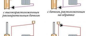
Variants of the Tichelman scheme
With the correct construction of the Tichelman scheme, the heating system assumes the creation of identical conditions for the operation of the radiator. This applies to pressure drops, despite the fact that radiators have equal surface areas, and, consequently, an equal level of heat transfer. To draw diagrams correctly, you need to practice for some time.
The door can be bypassed in several ways: the pipe can be laid on top. When choosing this option, please note that the area above the door must be equipped with an automatic air vent: this will not allow air to accumulate. The appearance of the room suffers. Also, the air vent may leak from time to time, which is quite impractical.
Variants of the Tichelman scheme:
- Option in a one-story house. The pipe can be laid below the floor level. But this can be inconvenient if the flooring has already been done.
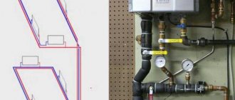
- Scheme for two floors. According to the scheme, the entire system is tied together, not individual floors. The supply and return of main pipes having a diameter of 20 mm are carried out. And radiators are already connected to them using a 16 mm tube.
- Trim for three floors. One piping is performed for all floors. The risers have a diameter of 25 mm, supply and return are 20 mm, the pipe for the outlet to the radiators is 16 mm.
If possible, it is better to connect each floor separately, while connecting an individual pump for each. It should be taken into account that the use of one pump if it breaks down can lead to the entire heating system failing at once. The Tichelman scheme can be used for heating installations in all types of premises. It involves uniform heating of the radiators, and it is quite easy to install if the circuit is drawn up correctly.
Tichelman system in a two-story house
In a private house, residents prefer to use autonomous heating systems. To obtain thermal energy, an independent heat generator is used. Typically these generators are medium-sized boilers. The most efficient and popular is the connection diagram called “Tichelman Scheme”.
Tichelman's scheme assumes that radiators operate under the same conditions, have the same resistance, and the quality of coolant flow.
The advantage of the circuit is its ability to self-balance. One branch of the circuit can be used to connect two houses. Provided that forced circulation of the coolant is used. The classic two-pipe circuit assumes that the return line starts from the last battery, and the end of the circuit is where the boiler is located. But Tichelman’s scheme has the opposite design.
Advantages of the scheme:
- System balance;
- Lack of adjustment equipment;
- Same flow throughout the entire heating system;
- Optimal operation of heat control equipment.
The scheme also has disadvantages. In order for it to work correctly and efficiently, it is necessary to use additional pipes with a large diameter. Purchasing equipment involves additional costs.
Traditionally used heating schemes
- Single-pipe. The coolant circulates through one pipe without the use of pumps. On the main line, radiator batteries are connected in series; from the very last, the cooled medium (“return”) is returned to the boiler through a pipe. The system is simple to implement and economical due to the need for fewer pipes. But the parallel movement of flows leads to a gradual cooling of the water; as a result, the media arrives at the radiators located at the end of the series chain significantly cooled. This effect increases with increasing number of radiator sections. Therefore, in rooms located near the boiler it will be excessively hot, and in remote ones it will be cold. To increase heat transfer, the number of sections in the batteries is increased, different pipe diameters are installed, additional control valves are installed, and each radiator is equipped with bypasses.
- Two-pipe. Each radiator battery is connected in parallel to the direct supply of hot coolant and the “return” pipes. That is, each device is equipped with an individual return outlet. With the simultaneous discharge of cooled water into the common circuit, the coolant is returned to the boiler for heating. But at the same time, the heating of heating devices gradually decreases as they move away from the heat supply sources. The radiator, located first in the network, receives the hottest water and is the first to return the coolant to the “return” circuit, and the radiator located at the end receives the coolant last with a lower heating temperature and is also the last to return water to the return circuit. In practice, in the first device the circulation of hot water is the best, and in the last the worst. It is worth noting the increased price of such systems compared to single-pipe systems.
Both schemes are justified for small areas, but are ineffective for extended networks.
An improved two-pipe heating scheme is the Tichelman heating scheme. When choosing a specific system, the determining factors are the availability of financial capabilities and the ability to provide the heating system with equipment that has the optimal required characteristics.
Operating principle of a single-pipe heating system
The operation of a single-pipe heating system follows fairly simple principles. There is only one closed pipeline through which the coolant circulates. Passing through the boiler, the medium heats up, and passing through the radiators imparts this heat to them, after which, cooled, it again enters the boiler.
There is also only one riser in a single-pipe system, and its location depends on the type of building. So, for one-story private houses a horizontal scheme is best suited, while for multi-story buildings - a vertical one.
Note! To pump coolant through vertical risers, a hydraulic pump may be needed.
To improve the efficiency of a single-pipe system, several improvements can be made. For example, install bypasses - special elements that are pipe sections connecting the forward and return radiator pipes.
This solution makes it possible to connect thermostats to the radiator that can control the temperature of each heating element, or completely disconnect them from the system. Another advantage of bypasses is that they allow you to replace or repair individual heating elements without shutting down the entire system.
Installation features
In order for the heating system to provide warmth to the owners of the house for many years, during the installation process it is worth adhering to the following sequence of actions:
- According to the developed project, the boiler is installed.
- The pipeline is being installed. In places where the project provides for the installation of radiators and bypasses, tees are installed.
- If the system operates on the principle of natural circulation, it is necessary to ensure a slope of 3-5 cm per meter of length. For a forced circulation circuit, a slope of 1 cm per meter of length will be sufficient.
- For systems with forced circulation, a circulation pump is installed. It is worth considering that the device is not designed for operation at high temperatures, so it would be better to install it near the entrance of the return pipe to the boiler. In addition, the pump must be connected to the electrical network.
- Installation of expansion tank. An open type tank should be located at the highest point of the system, a closed type - in any convenient place (most often it is mounted near the boiler).
- Installation of heating radiators. They weigh a lot (especially when filled with water), so they are secured using special brackets, which are usually included in the kit. Installation is most often carried out under window openings.
- Additional devices are being installed - Mayevsky taps, plugs, shut-off devices.
- The final stage is testing the finished system, for which water or air is supplied to it under pressure. If the tests do not reveal problem areas, the system is ready for operation.
Note! During installation, a large number of bends in the pipeline should be avoided if possible. This reduces the coolant circulation rate and degrades the efficiency of the heating system.
Advantages
For private houses with a small area, a single-pipe heating system looks more preferable due to its following advantages:
- Ease of drafting.
- Ease of installation of the system.
- Reducing costs for the purchase of materials and equipment.
- Steady hydrodynamics.
- Safety of coolant circulation, which occurs naturally.
Flaws
There are also a number of disadvantages that owners of single-pipe heating systems will have to put up with:
- Difficulty in correcting errors made at the design stage in a commissioned circuit.
- Uneven heating of heating elements located at different distances from the boiler.
- Close interdependence of elements.
- High hydrodynamic resistance.
- Impossibility of adjusting coolant flow.
- Relatively large heat losses.
- Limited number of radiators that can be placed on one riser.
What is Tichelman's loop
The Tichelman loop (also called a “passing circuit”) is a heating system pipe routing diagram. This scheme simultaneously combines the advantages of two common schemes: Leningrad and two-pipe, while having additional advantages.
Compared with a two-pipe scheme, when using a Tichelman loop there is no need to install expensive control systems. Heating devices work like one large radiator. The coolant flow is the same throughout the entire heating circuit. There are no narrowing pipes and dead-end radiators, where the flow is worst. The disadvantage compared to a two-pipe heating scheme is that the entire branch must be made with a large-diameter pipe, which can greatly affect the cost of the entire system as a whole.
If we compare it with the Leningrad (single-pipe) scheme, the advantage is that the coolant will not pass through the pipe past the radiator. The Leningrad circuit is very demanding in terms of circuit design and installation. If you are not highly skilled in performing either the first or the second, it will be impossible to force water to pass through the heating device; it will pass through the pipe. The radiator will remain slightly warm. In addition, in the Leningrad scheme, the first radiators in terms of water flow will be hotter than the next ones. Since the water will reach them already cooled. The disadvantage of the Tichelman loop compared to the Leningrad loop is that the pipe flow rate almost doubles.
Of the general advantages, I would like to note that such a scheme is difficult to unbalance. The conditions for coolant movement are almost ideal, which also has a positive effect on the operation of the heat generator (be it a boiler, solar systems or something else).
The main disadvantage of the associated heating scheme is certain requirements for the room. In practice, it is not always possible to organize a circular movement of the coolant. Doorways, architectural features, etc. may interfere. In addition, it can only be used for horizontal wiring; for vertical wiring, the Tichelman loop is not applicable.
Albert Tichelman's solution
The German engineer Albert Tichelman in 1901 proposed using the so-called “reverse-type return system”, changing the principle of operation of the “return”. Which later became known as heating with a Tichelman loop (accompanying scheme). According to his idea, the first radiator to receive hot coolant became the last in the “return”, and the first in the “return” (closest to the boiler) received exactly the same hot coolant last. As a result, the coolant circulation throughout the entire circuit improved, and equal heating of all radiators was ensured, the need for additional control valves and the purchase of radiators of different sizes was eliminated, the coolant received easy flow conditions, and the heating boilers were finally able to show their true efficiency.
The only problem was that in 1901 this system could only function in one-story buildings, that is, strictly horizontally. However, with the advent of circulation pumps that forcefully pump coolant through the system, the two-pipe heating system showed itself in all its glory.
Modern distribution manifolds reveal all the new advantages of this scheme, making it possible to combine in one house both the radiators familiar to everyone and a water heated floor system.
The disadvantages of Tichelman's associated heating scheme should still include the need to purchase, in addition to the main ones, additional large-diameter pipes, which is associated with additional costs, and the architectural features of a private house should also be taken into account when designing, since obstacles to the implementation of such a scheme may be, for example, doorways, as well as other architectural forms.
System Description
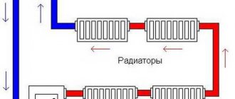
In professional circles, the Tichelman loop is called a two-pipe heating system with a parallel movement of the coolant. This name fully reflects the essence and principle of operation; the distinctive features are best seen against the background of a two-pipe system with reverse flow of coolant, which is familiar to almost everyone.
Let's imagine a radiator network deployed in a straight row. In the classical scheme, the heating unit is located at the beginning of this row, from which two pipes follow along the entire network for supplying hot and returning cold coolant, respectively. Moreover, each radiator is a kind of shunt, therefore, the greater the distance of the heating device from the thermal unit, the higher the hydraulic resistance in its connection loop.
If we roll a row of radiators into a ring, then both of its edges will be adjacent to the thermal unit. In this case, it is much more profitable to make sure that the return pipeline does not direct the coolant back to the boiler room, but continues to follow further along the chain, that is, along with the supply. In other words, the supply pipe follows from the heating unit and ends at the outer radiator, in turn, the return pipe originates from the first radiator and is directed to the boiler room. The same principle can be implemented even if the radiators are located linearly in space, simply from the point where the outermost radiator is inserted into the return line, the pipe turns around to return the cooled coolant. In this case, in a certain area the heating system will be three-pipe, as the Tichelman loop is also sometimes called.
But why do we need such complications? If you carefully study the diagram, you will find that the sum of the lengths of the supply and return pipelines for each radiator is the same. Hence the conclusion: the hydraulic resistance of each individual connection loop is equivalent to the remaining sections, that is, the system simply does not need balancing.
System installation
When installing the structure, certain rules should be followed:
- any two-pipe system includes 2 circuits: the upper one serves to supply hot coolant to the radiators, the lower one to remove cooled fluid;
- the pipeline should have a slight slope towards the final radiator;
- the pipes of both circuits must be parallel;
- the central riser must be insulated to prevent heat losses when supplying coolant;
- in reversible two-pipe systems, it is necessary to provide several taps with which it is possible to drain water from the device. This may be needed during repair work;
- when designing a pipeline, it is necessary to provide for the smallest possible number of angles;
- the expansion tank must be installed at the highest point of the system;
- the diameters of pipes, taps, pipes, connections must match;
- When installing a pipeline made of heavy steel pipes, special fasteners must be installed to support them. The maximum distance between them is 1.2 m.
How to make the correct connection of heating radiators, which will ensure the most comfortable conditions in the apartment? When installing two-pipe heating systems, you must adhere to the following sequence:
- The central riser of the heating system is diverted from the heating boiler.
- At the highest point, the central riser ends with an expansion tank.
- Pipes run from it throughout the building, supplying hot coolant to the radiators.
- To remove cooled coolant from heating radiators with a two-pipe design, a pipeline is laid parallel to the supply one. It must be connected to the bottom of the heating boiler.
- For systems with forced circulation of coolant, an electric pump must be provided. It can be installed at any convenient point. Most often it is installed near the boiler, near the entry or exit point.
Connecting a heating radiator is not such a difficult process if you approach this issue scrupulously.
Tichelman loop - reliable heating for large houses, how to make it
If such a circuit is formed as a closed ring, then both edges become as close as possible to the heating device and the return flow pipeline is not directed to the boiler compartment, but continues further along the chain. In this case, the Tichelman heating scheme requires extending the supply pipeline from the heating device to the last radiator, while the return line goes along the line from the first battery and ends in the boiler compartment.
The scheme is also implemented in the case of a linear arrangement of heating radiators. In this situation, the return flow pipe must be deployed in the insertion area of the last battery and the cooled coolant will return to the heating device. It turns out that in a certain section of the main line the system turns into a two-pipe system, which is why the Tichelman loop is also called a 2-pipe distribution.
On a note! In terms of the total length, the supply and return pipelines for each radiator are equivalent, so balancing the heating system when laying out the Tichelman circuit is not required. Due to the identical thermal power of the batteries, the design ensures uniform heat supply to the radiators at any distance from the heating device. It is not recommended to use the Tichelman loop in small houses; here it is more convenient to equip a dead-end heating system. Increased consumption of materials is not always better, so the Tichelman system is rarely used in a two-story house.
The exception is a highway with radiators placed around the perimeter of the building. We will have to lay another line to return the coolant to the heating device. If the loop is lengthened, moved away from the heater, the cross-section of the pipes is increased, or a powerful circulation pump is selected, otherwise the system will not be able to operate at full capacity.
Naturally, in the process of designing a heating system diagram in a specific architectural object, it is necessary to decide what the diameter of the pipes in the structure should be. In this case, the calculation of general heat and power indicators is assumed. This must be done first, since otherwise the installation of heating will be difficult. So, in the process of determining the diameter of the pipes, we calculate the power of the structure.
To reduce coolant costs in the area where the first batteries are connected, the diameter of the pipeline should be reduced, this will help maintain water pressure in subsequent sections. The diameter is reduced only according to preliminary calculations, otherwise radiators located at a considerable distance from the heating device will not receive a sufficient amount of coolant.
Advantages and disadvantages
The Tichelman system is gaining momentum and owners of private houses are increasingly giving preference to it, this is certainly due to a number of advantages that it has:
- The system is universal, suitable for rooms of different sizes, from the smallest to large areas. These can be both domestic and industrial premises;
- if desired, you can install several heating units at once;
- the rooms are warmed up efficiently, and the heat is distributed evenly;
- no complex balancing is required, and there is no need to install expensive adjustment equipment;
- There are no difficulties in installation, the main thing is to strictly follow the technology;
- The system has a long service life.
Despite the large number of advantages, there are some disadvantages that also need to be taken into account when installing a Tichelman heating system:
- such a system will cost a pretty penny, due to the increased length of the pipelines and the inadmissibility of using small diameters;
- Difficulties may arise with the loop, because it is not always possible to lay it around the perimeter of the house due to the peculiarities of the construction in each individual case (for example, too high window and door openings, flights of stairs, etc.);
- However, thanks to the advent of modern circulation pumps, which allow efficient pumping of coolant, the associated heating system has gained wide popularity.
Features of a dead-end heating system.
The procedure for performing installation work
The work consists of the following operations:
- Boiler installation. The required minimum room height for its placement is 2.5 m, the permissible volume of the room is 8 cubic meters. m. The required power of the equipment is determined by calculation (examples are given in special reference publications). Approximately for heating 10 square meters. m requires a power of 1 kW.
- Hangment of radiator sections. The use of biometric products in private homes is recommended. After selecting the required number of radiators, their location is marked (usually under window openings) and secured using special brackets.
- Extension of the associated heating system line. It is optimal to use metal-plastic pipes that successfully withstand high temperatures, are durable and easy to install. The main pipelines (supply and return) are from 20 to 26 mm and 16 mm for connecting radiators.
- Installation of a circulation pump. Mounted on the return pipe near the boiler. The insertion is carried out through a bypass with 3 taps. It is necessary to install a special filter in front of the pump, which will significantly increase the service life of the device.
- Installation of an expansion tank and elements ensuring the safe operation of the equipment. For a heating system with a passing coolant movement, only membrane expansion tanks are selected. Safety group elements are supplied with the boiler.
To line doorways with a main line in utility rooms and utility rooms, it is allowed to install pipes directly above the door. In this place, to prevent air accumulation, automatic air vents must be installed. In residential areas, pipes can be laid under a door in the body of the floor or bypassing an obstacle using a third pipe.
Tichelman’s scheme for two-story houses provides for a certain technology. Pipe distribution is carried out with tying the entire building, and not each floor separately. It is recommended to install one circulation pump on each floor, maintaining equal lengths of return and supply pipelines for each radiator separately in accordance with the basic conditions of the associated two-pipe heating system. If you install one pump, which is quite acceptable, then if it fails, the heating system in the entire building will shut down.
Many experts consider it expedient to install a common riser on two floors with separate piping on each floor. This will make it possible to take into account the difference in heat loss on each floor with the selection of pipe diameters and the number of required sections in radiator batteries.
A separate associated heating circuit on the floors will greatly simplify the setup of the system and allow for optimal balancing of the heating of the entire building. But to obtain the desired effect, it is necessary to insert a balancing crane into the travel circuit for each of the two floors. The taps can be placed side by side directly next to the boiler.
System installation process
Work on installing Tichelman heating begins with the installation of a boiler, which should be placed in a room no lower than 250 cm. The power of the device depends on the heated area: 1000 W are required for 10 m2 of area.
After this you need to do the following:
- Hang the radiator sections. Having determined the required number of elements, mark their future location - usually they are placed under windows. Secure the radiators with brackets.
- Stretch metal-plastic pipes through which the supply and return will go. This material is recommended due to its ease of installation and resistance to high temperatures. The diameters should be 20-25 mm (at main pipes) and 16 mm (battery connection).
- Mount the circulation pump on the return line next to the boiler. A filtration device must be placed in front of it. The pump is installed through a bypass with three taps.
- Install the expansion tank and safety parts responsible for the safety of the system.
The simplest and most inexpensive method of water preparation is the use of an indirect boiler in the Tichelman loop. Automated boilers are usually easily connected to and controlled by the heating device. Otherwise, to turn on the boiler, you will need to create a piping.
In utility and outbuildings it is considered acceptable to place a bypass pipeline directly above the doors. In this case, an air exhaust device must be placed at the highest point of the configuration, and a drain mechanism must be installed at the lower point.
Pros of the scheme
More and more owners of private houses are deciding to install heating systems according to the Tichelman scheme. This is not surprising; it has quite a number of advantages:
Probably the most important advantage of this method is that such a heating system allows all heating devices to work as efficiently as possible. For example, the supply and return lines are connected together, going in the same direction of the radiator chain, the heat transfer of each subsequent radiator decreases, the latter may generally remain cold; The pipes run along two separate circuits in the same direction, the efficiency of the radiators becomes noticeably higher, continuing to decrease; Thanks to the Tichelman loop, radiators are able to operate at 100%; The system is adaptive in nature; small and large premises for domestic or industrial purposes are suitable for installation; Each radiator provides the same amount of heat, so the room will warm up evenly; The method is simple to implement, has no complicated steps, it is only important to follow the technology; There is the possibility of installing additional heating devices; Since the radiators are already balanced, there is no need to waste time on balancing them for uniform heating; installation of the system does not require the purchase of any additional elements; Heating installed according to the Tichelman scheme will last a very long time.
Schematic diagram of Tichelman heating
Disadvantages of the scheme
- Heating according to the Tichelman scheme is not a cheap pleasure; the system requires a fairly long length of pipelines, so for the sake of convenience you will have to pay a certain amount. This is the most significant disadvantage;
- Laying a heating system according to such a scheme causes many problems due to interfering architectural features of the premises (doorways, for example). It is because of this moment that the Tichelman loop can be impossible to lay;
- This scheme is drawn horizontally. When laying the heating system vertically, you will have to use other schemes.
Algorithm for performing installation work
The installation of a two-pipe associated heating system is carried out in accordance with a certain algorithm, where the initial stage is the selection of pipe diameters, and the final stage is the installation of a circulator pump.
Calculation of pipeline diameter
There is a scientifically based method of calculation. The cross-section of the pipe is selected based on the volume of coolant passing through the pipe per unit time. The calculation starts from the distant radiator using the formula:
G=3600×Q/(c×Δt), (1)
where: G – water consumption for heating the house (kg/h);
Q is the thermal power required for heating (kW);
c – heat capacity of water (4.187 kJ/kg×°C);
Δt is the temperature difference between the hot and cold coolant, taken equal to 20 °C.
Next, calculate the cross-section of the pipes using the formula:
S=GV/(3600×v), (2)
where: S is the cross-sectional area of the pipe (m2);
GV – volumetric water flow (m3/h);
v is the speed of water movement, is in the range of 0.3−0.7 m/s.
The resulting figure is the cross-section; based on it, the internal diameter of the pipeline is selected.
This calculation is carried out for all radiators up to the boiler.
When calculating, you can also rely on the table of the dependence of the internal diameter of the pipe on the thermal load.
Table of dependence of the internal diameter of the pipe on the thermal load
The following guidelines can be taken into account:
- For heat losses of up to 15 kW (150 sq. m.) of area, pipes with a diameter of 20 mm are suitable.
- For losses from 15 to 27 kW (up to 250 square meters), pipes with a diameter of at least 25 mm will be required.
Carrying out calculations using the given formulas or hydraulic tables is a difficult task for the homeowner, so you can rely on the recommended pipe diameters.
The diameter of the pipeline must be the same throughout its entire length to ensure stable operation of the batteries. The recommended minimum internal diameter of pipes is 20 mm.
The following conditions must be met:
- Place pipes under the floor covering to avoid high-rise contours. If this is not possible, then you need to take into account the configuration of the house and strive as much as possible for the same height of pipe laying.
- Pipe material is metal-plastic or polypropylene reinforced with aluminum foil. Such pipes are stronger and will last a long time.
- Radiators are installed bimetallic or steel with a bottom connection system. Such batteries have higher hydraulic resistance, which balances the system. The power of the radiators should be the same throughout the entire area of the house.
- Each battery is equipped with a balancing valve on the return line. It is advisable to install thermostats.
Boiler installation
The room where the boiler is installed must have a height of at least 2.5 m. The volume of the room is recommended from 8 cubic meters. The hot water boiler must be selected depending on the area of the heated house. Boiler power for heating is 10 kW. m is equal to 1 kW. Based on this, the power for the entire system is selected.
The boiler piping consists of a set of shut-off valves; it is installed in several places:
- On the make-up pipe.
- On both sides of the pump.
- At the expansion tank.
- On the pipes coming from the boiler.
Mainline pulling
When installing the associated heating system distribution line, the following must be taken into account:
- The outlet branch of the main line must be located below the supply branch.
- The heat supply and heat removal pipes must be parallel to each other.
- The expansion tank must be installed above the heating boiler.
- Valves for draining water must be installed on the connecting radiators. It is recommended to install a thermostatic head on each radiator to ensure a comfortable temperature.
- When laying the pipeline, right angles are excluded to avoid the occurrence of air locks in the system.
- The expansion tank must be installed in a heated room.
- All diameters of pipes, fittings and taps must match each other. You cannot install pipes of different diameters in an attempt to save money. The water pressure in the system will be disrupted.
Installing a circulation pump
It is unreasonable to rely on natural circulation, since there are 10 or more batteries in the associated heating system. Gravity will not be able to work without forced pressure. The circulation pump is installed on the return branch near the boiler. The pump is installed using a bypass and three valves. It is recommended to install a filter.
The associated heating system is installed in one-story and two-story buildings. In two-story buildings, during installation you need to take into account some nuances:
- A circulation pump is installed on each floor. If a breakdown occurs on one floor, the heating will work fully on the other.
- For each floor it is recommended to install according to a separate scheme.
The diameters in the Tichelman loop are selected in the same way as in a two-pipe dead-end heating system. Where the flow rate is greater, the diameter is larger. The farther from the boiler, the lower the consumption may be.
If you choose the wrong diameters, then medium radiators will not heat well.
More about the program
If you do not create artificial hydraulic resistance to the radiator branches in the pressure heating system, then the average radiators will not heat badly either.
What conditions must be observed in the Tichelman loop in order for medium radiators to heat well?
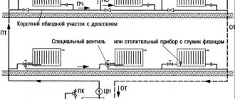
Each radiator branch must have a hydraulic resistance of 0.5-1 Kvs. This resistance can be produced by a thermostatic or balancing valve, which is placed on the radiator line. As a rule, when savings are made on thermostatic and balancing valves (that is, they are not installed), then each radiator branch begins to have low hydraulic resistance, which is comparable to what would happen if you simply connected the supply and return with a pipe (Roughly made a bypass).
Note:
For gravity heating systems with natural circulation, radiator branches do not need to create artificial resistance. Because due to the natural pressure of the coolant, the radiator branch itself influences its flow rate.
The Tichelman loop can be used without a pump, but only with large diameters, as is done for gravity heating systems with natural circulation. And to calculate the diameters, the heating system simulator program will help you: Read more about the program
What diameters to choose in the Tichelman loop?
The diameters in the Tichelman loop are not an easy task, as is the choice of diameters in a two-pipe dead-end heating system. The principle for choosing diameters depends on flow rates and pressure losses in the pipeline.
Below you will see how diameters are selected.
Bad Tichelmann loop circuits
Medium radiators will work poorly if there is no artificial hydraulic resistance on the radiator branches. Artificial resistance is created by balancing or thermostatic valves. Which have a throughput of 0.5 - 1.1 Kvs.
Pressure heating system with ball valves and 20 mm polypropylene pipe.
You cannot do this on ball valves:
This radiator branch has low hydraulic resistance. It will consume a lot of fuel and there will be little left for other radiators.
A circuit for 5 radiators with a 25mm PP main pipe was tested.
Radiator costs are not the same. The third radiator has the lowest flow rate. This is due to the fact that there are ball valves on the radiator branches.
If you add thermostatic valves to the circuit, the costs become more equally divided:
The picture is already better! But the diameters can be reduced in some places and save on this. For example, there are up to 4 radiators in the supply line and 2 radiators in the return line.
If we try to leave PP20mm on the entire highway, we will get the following costs.
If we used a thermal valve or any regulating device at 2 Kvs, then a change in diameters would have to be done!
Because if someone opens the tap completely, it will prevent other radiators from working normally. There are control valves for radiators at 5 Kvs. Well, if you are going to tighten the bottom valve to reduce the throughput, then do this kind of adjustment. Of course, it would be better to use closed balancing valves that cannot be adjusted by unauthorized people.
In order to improve the distribution of costs among 5 radiators using control valves with higher throughput, it is necessary to use PP32, PP25 and PP20 pipes.
Good Tichelmann loop chains
Diameter selection criteria:
The choice of diameters for the Tichelman loop was selected based on a chain drop of a maximum of 1 m.v.st. The temperature difference of the radiators is 20 degrees. The inlet temperature is 90 degrees. The difference in output power between radiators does not exceed 200 W. The difference in temperature differences between radiators does not exceed 5 degrees.
Note:
The indicated diameters do not apply to low temperature heating systems. For low-temperature systems, it is necessary to reduce the temperature difference to 10 degrees and this requires a doubling of the flow rate.
I prepared Tichelman loop chains for 5 and 7 radiators for metal-plastic and polypropylene pipes.
5 radiators polypropylene pipe, Kvs = 0.5.
5 radiators metal-plastic pipe, Kvs = 0.5.
7 radiators polypropylene pipe, Kvs = 0.5.
This chain uses 32mm PP. If you install a balancing valve on radiators 1 and 7, you can change the pipe from PP32 to PP26 mm. It is necessary to tighten the balancing valves on radiators 1 and 7.
7 radiators metal-plastic pipe, Kvs = 0.5.
Tests on the selection of diameters were carried out in the heating system simulator program.
More information about the simulator program
The program is used to test heating systems before installation on site. It is also possible to test existing heating systems to improve the performance of the existing heating system.
If you need diameter calculations for your heating system for 10 radiators, then apply for calculation services here: Order a calculation service
Calculation of the Tichelmann loop
As in a two-pipe dead-end heating system, the diameters also have to be selected based on the flow rate and pressure loss of the coolant. The Tichelman loop is a complex circuit, and the mathematical calculation becomes very complicated.
If in a two-pipe dead-end circuit the equation looks simpler, then for a Tichelman loop the circuit equation looks like this:
More details about this calculation are described in the video course on heating calculations here: Video course on heating calculations
How to set up a Tichelman loop? How to set up a secondary heating system?
As a rule, the Tichelman loop has conditions when the middle radiators do not heat well; in this case, as in a dead-end pipe, we clamp the balancing valves on the radiators located closer to the boiler. The closer the radiators are to the boiler, the tighter we clamp them.
| Like |
| Share |
| Comments (+) [ Read / Add ] |
A series of video tutorials on a private house
Part 1. Where to drill a well?
Part 2. Construction of a water well Part 3. Laying a pipeline from the well to the house Part 4. Automatic water supply Water supply Water
supply for a private house.
Principle of operation. Connection diagram Self-priming surface pumps. Principle of operation. Connection diagram Calculation of a self-priming pump Calculation of diameters from a central water supply Water supply pumping station How to choose a pump for a well? Setting up a pressure switch Pressure switch electrical diagram Operating principle of a hydraulic accumulator Sewage slope of 1 meter SNIP Connecting a heated towel rail Heating diagrams
Hydraulic calculation of a two-pipe heating system Hydraulic calculation of a two-pipe associated heating system Tichelman loop Hydraulic calculation of a single-pipe heating system Hydraulic calculation of radial distribution of a heating system Scheme with a heat pump and solid fuel boiler - logic of operation Three-way valve from Valtec + thermal head with remote sensor Why the heating radiator in an apartment building does not heat well How to connect the boiler to the boiler?
Options and connection diagrams DHW recirculation. Principle of operation and calculation You are not correctly calculating the hydraulic needle and collectors. Manual hydraulic calculation of heating. Calculation of a warm water floor and mixing units. Three-way valve with a servo drive for DHW. Calculation of DHW, BKN. We find the volume, power of the snake, warm-up time, etc. Water supply and heating designer
Bernoulli's equation Calculation of water supply for apartment buildings
Automation
How servos and three-way valves work Three-way valve to redirect the movement of coolant
Heating
Calculation of the thermal power of heating radiators Radiator section Overgrowth and deposits in pipes worsen the performance of the water supply and heating system New pumps work differently... Calculation infiltration Calculation of temperature in an unheated room Calculation of a floor based on the ground Calculation of a heat accumulator Calculation of a heat accumulator for a solid fuel boiler Calculation of a heat accumulator for storing thermal energy Where to connect the expansion tank in the heating system?
Boiler resistance Tichelman loop pipe diameter How to choose the diameter of a pipe for heating Heat transfer of a pipe Gravity heating from a polypropylene pipe Why don’t they like single-pipe heating? How to love her? Smart selection of diameters in a heating system Balancing heating radiators - a step-by-step guide Top 5 problems in designing heating systems Heat regulators
Room thermostat - operating principle
Mixing unit
What is a mixing unit?
Types of mixing units for heating Characteristics and parameters of systems
Local hydraulic resistance.
What is KMS? Bandwidth Kvs. What it is? Boiling water under pressure - what will happen? What is hysteresis in temperatures and pressures? What is infiltration? What are DN, Du and PN? Plumbers and engineers must know these parameters! Hydraulic meanings, concepts and calculation of heating system circuits. Flow coefficient in a single-pipe heating system. Hydraulic paradox in a heating system. Riddle No. 4 Video
Heating Automatic temperature control Simple replenishment of the heating system Heat engineering.
Walling. Warm water floor Combimix pump mixing unit Why choose underfloor heating? Water heated floor VALTEC. Video seminar Pipe for heated floors - what to choose? Warm water floor - theory, advantages and disadvantages Laying warm water floor - theory and rules Warm floors in a wooden house. Dry heated floor. Warm water floor cake - theory and calculation News for plumbers and engineers Plumbers Are you still doing hack work? The first results of the development of a new program with realistic three-dimensional graphics Thermal calculation program. The second result of the development of Teplo-Raschet 3D Program for thermal calculation of a house through enclosing structures Results of the development of a new program for hydraulic calculation Primary secondary rings of the heating system One pump for radiators and underfloor heating Calculation of heat loss at home - wall orientation? Regulatory documents
Regulatory requirements for the design of boiler houses Abbreviations
Terms and definitions
Basement, basement, floor Boiler houses
Documentary water supply
Sources of water supply Physical properties of natural water Chemical composition of natural water Bacterial contamination of water Requirements for water quality
Collection of questions
Is it possible to place a gas boiler room in the basement of a residential building ?
Is it possible to attach a boiler room to a residential building? Is it possible to place a gas boiler room on the roof of a residential building? How are boiler rooms classified according to their location? Personal experiences in hydraulics and heating engineering
Introduction and introduction.
Part 1 Hydraulic resistance of a thermostatic valve Hydraulic resistance of a filter flask Video course Calculation programs
Technotronic8 - Program for hydraulic and thermal calculations Auto-Snab 3D - Hydraulic calculation in three-dimensional space
Useful materials Useful literature
Hydrostatics and hydrodynamics
Problems in hydraulic calculations
Pressure loss along a straight section of a pipe How does head loss affect flow?
Miscellaneous
Do-it-yourself water supply for a private house Autonomous water supply Scheme of autonomous water supply Scheme of automatic water supply Scheme of water supply for a private house
Privacy Policy
Heating two-pipe floor-by-floor system: features of arranging a private house
As the name implies, the two-pipe heating system of a two-story house consists of two main pipelines supplying batteries and other heaters from the boiler.
One pipeline contains hot water, which heats the radiators, and the second contains cold water from the radiators, which flows back into the gas boiler to heat a private house.
A single-pipe heating system for a two-story house is just as effective as a two-pipe one.
You can give several examples to understand how effective the use of a hot water line without return is:
- Heating speed and high coolant efficiency.
- Economical. When using a two-pipe heating system, it is possible to easily control the air temperature in the building, achieving the required level of comfort.
- Possibility of choosing the most optimal heating device scheme.
Diagrams of a two-pipe heating system for a two-story house
Scheme of a horizontal two-pipe manifold heating system.
A one-pipe heating system for a two-story house, like a two-pipe one, provides for the installation of radiators and pipelines according to several main schemes.
Each of these schemes, naturally, has its own advantages and features, which would be worth considering:
- Beam circuit with distributor. This diagram of a two-pipe heating system for a two-story house is widespread, and its popularity lies in the personal installation of the coolant outlet and supply. Pipe installation is often done directly into the floor.
- Among the advantages of this scheme: preservation of the composition of the interior style, the most effective heating control, adjustment of the coolant supply.
- The sequential scheme for supplying coolant is very popular among owners of small two-story country houses due to its low material consumption.
- This scheme involves sequentially connecting return and supply pipes to each heating battery (the usual one-pipe heating scheme of a two-story house is very similar to it).
- Thanks to the use of a sequential two-pipe heating circuit, the price of the device is reduced, and it becomes possible to install an individual thermal regulator on each radiator.
Two-pipe heating systems of a two-story private house: modernization of wiring
Heating diagram for a two-story house.
- Due to the characteristics of each individual two-story house, property owners often modify the installed heating themselves.
- This is very practical and convenient, since installation instructions are not always standardized and sometimes do not make it possible to achieve high operating efficiency of heating equipment.
- It should be noted that many videos and photos on the Internet show that the greatest demand among country home owners is to install a pump and expansion tank in a two-pipe heating system.
Scheme of a two-pipe water heating system with natural circulation.
Thanks to such upgrades, it is possible to increase work productivity, efficiency, and also reduce the cost of heating the coolant:
- Installation of the expansion tank. This device must be placed almost at the highest point of the house - for example, in the attic of cottages.
- Thanks to such a tank, the coolant will circulate freely in the heating main without creating excess pressure;
- Recommendation: it is advisable to install a large volume tank “with a reserve”, as this will help ensure constant circulation of the required volume of coolant.
- Pump installation. Heating for a modern three- or two-story country house with natural circulation (gravity heating) is a rather outdated option.
- Today, installing a special pump helps increase productivity.
Inserting the return line directly into the pipeline of a special pump makes it possible to significantly speed up heating to the optimal temperature, saving money on the purchase of fuel.
The coolant, moreover, circulates much faster with the pump, accordingly, thanks to this there will always be an optimal temperature in the house, including on the second floor.
Types of two-pipe heating systems
There are several criteria by which such heating structures can be classified.
Open and closed
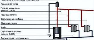
Closed systems require the use of an expansion tank with a membrane. They can operate at elevated pressure. Instead of ordinary water in closed systems, you can use ethylene glycol-based coolants, which do not freeze at low temperatures (up to 40 °C below zero). Motorists know such liquids as “antifreeze.”
1. Heating boiler; 2. Security group; 3. Excess pressure relief valve; 4. Radiator; 5. Return pipe; 6. Expansion tank; 7. Valve; 8. Drain valve; 9. Circulation pump; 10. Pressure gauge; 11. Make-up valve.
An open system is characterized by the fact that the expansion tank must be installed strictly at the highest point of the device. It must be equipped with an air pipe and a drain pipe through which excess water is drained from the system. You can also take warm water for household needs through it. However, such use of the tank requires automatic replenishment of the structure and eliminates the possibility of using additives and additives.
1. Heating boiler; 2. Circulation pump; 3. Heating devices; 4. Differential valve; 5. Gate valves; 6. Expansion tank.
Horizontal and vertical
These types differ in the location of the main pipeline. It serves to connect all structural elements. Both horizontal and vertical systems have their own advantages and disadvantages. However, both of them demonstrate good heat transfer and hydraulic stability.
A two-pipe horizontal heating design is found in one-story buildings, and a vertical in high-rise buildings. It is more complex and, accordingly, more expensive. Here vertical risers are used, to which heating elements are connected on each floor. The advantage of vertical systems is that, as a rule, air locks do not occur in them, since the air flows through the pipes up to the expansion tank.
Systems with forced and natural circulation
These types differ in that, firstly, there is an electric pump that forces the coolant to move, and secondly, circulation occurs on its own, obeying physical laws. The disadvantage of pump designs is that they depend on the availability of electricity. For small rooms there is no particular point in forced systems, except that the house will heat up faster. For large areas, such designs will be justified.
To choose the right type of circulation, it is necessary to consider what type of pipe distribution is used: upper or lower.
A system with overhead distribution involves laying a main pipeline under the ceiling of the building. This ensures high coolant pressure, due to which it flows well through the radiators, which means that the use of a pump will be unnecessary. Such devices look more aesthetically pleasing; the pipes at the top can be hidden with decorative elements. However, a membrane tank must be installed in this system, which entails additional costs. It is possible to install an open tank, but it must be at the highest point of the system, that is, in the attic. In this case, the tank must be insulated.
Boiler room piping
A two-pipe system with a parallel movement of coolant can be either open or closed. As we have already said, the main functioning element is the pump, so its installation cannot be avoided. You should not count on natural circulation even with properly organized upper pipe distribution. As we have already said, a typical Tichelman loop contains 10 or more radiators; it is unlikely to push through such an arm only by gravitational movement.
At the boiler supply outlet, a traditional safety “troika” is installed: an automatic air vent, a bleed valve and a pressure gauge. For open systems, the supply outlet must be organized in a vertical channel up to the height of the slope; an open expansion tank is installed at the highest point. Next, the supply pipe is sent directly to the distribution network.
One circulation pump is installed on the boiler return, the performance of which is determined by the hydraulic resistance of the entire system. Directly in front of the pump there is a strainer, and immediately after the pump there is a tee for connecting the expansion tank and a pressure gauge for the lower point. The filling pipe is also located in this place.
The shut-off valves of the boiler room are represented by full bore ball valves, which are installed:
- on both sides of the pump
- at the outlet of the expansion tank
- on the filling pipe
- at the points where the boiler is connected to the mains
Additionally, a connecting bypass tube can be installed in the boiler room, into the gap of which an electric normally closed valve is mounted, which is activated when the circulation stops. The bypass must be inserted before the circulation pump: the bypass is designed to protect against temperature shock and it bypasses the boiler heat exchanger from the main line, and not vice versa.
The Tichelman system is also good because, with a relatively high power radiator network, it is possible to operate from a boiler with a built-in set of hydraulic equipment. However, if it is necessary to coordinate the operation of the radiator network and the heated floor, each arm of the system is equipped with its own circulation pump. If the performance in the shoulders differs significantly, it is necessary to install a hydraulic arrow.
Inverter heating
Heating systems powered by electricity have many positive characteristics. The ease of installation of such equipment is that electricity is available in any building. In order to install inverter heating at home, you do not need to obtain permits. Also, the hyperinverter heating system saves space. Pay attention to the price. The cost of inverter heating equipment is significantly lower than other heating systems. The boiler can be replaced with an inverter, it is much cheaper.
How does DIY inverter heating work? Electricity enters the boiler through the heating element. Take care to protect equipment from damage and insulate the building to minimize heat loss. The operating principle of an inverter boiler is such that it constantly produces an induction current. In the event of a power outage, the boiler can operate on battery power. The boiler consists of two parts - the magnetic part and the heat exchanger.
Components of an inverter boiler
Why is an inverter boiler so good? Due to the fact that it does not have a heating element in its structure, this makes it more practical to use. Due to the fact that a pump is built into the system, the energy carrier warms up faster. There are no great requirements for fuel selection.
The operating principle is the same as that of an open dependent heating system, since the heating elements do not come into contact with various media.
However, do not forget that with all the positive characteristics, you can also find disadvantages. An inverter boiler costs much more than a heating element. Also, the boiler itself is quite large and is not suitable for rooms with a small area. To set the set temperature or reduce the indicators, you need to build an automatic control system into the boiler.
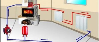
Gravity option
Gravity heating scheme. Click on photo to enlarge.
It is the simplest and most primitive. Consequently, such a system is cheap and not too difficult to implement, since it depends on the layout of the home. But this is where its disadvantages lie. It is a large metal pipe connected to the boiler and passing throughout the house (this is a prerequisite), through which the coolant flows.
The disadvantage of this scheme is the need for massive pipes with a large cross-section in diameter, since installing thinner ones or adding batteries to the system leads to a decrease in heating efficiency due to a decrease in the water flow rate. In order to increase the efficiency of this heating system, not one, but two pipes are installed in the house, which causes even greater inconvenience to the residents.
Technology for installing a Tichelman loop in a private home
The rules for forming a Tichelman heating scheme for a two-story house are simple:
- the main structural element is a hydraulic pump;
- a common heating riser is formed;
- each floor has its own loop;
- the diameter of pipes and batteries is selected separately for each floor;
- Install a balancing valve into the hitch circuit - on each individual floor.
Boiler piping
There is a distinction between open and closed two-pipe networks with associated coolant circulation. Since more than 10 radiators are connected, it is impossible to push the shoulder through gravitational forces, therefore a safety system consisting of an automatic air vent, a bleed valve and a water meter is installed at the outlet through the supply pipeline.
Scheme of a single-pipe heating system for a private house
The following are cut into the return circulation line:
- circulation pump, the power of which is determined in accordance with the hydraulic resistance of the network;
- a mesh dirt filter is integrated in front of the pump;
- after the pumping equipment, a tee is inserted to connect the expansion tank and the lower point pressure gauge;
- a drain or filling pipe is cut into the installation area of the safety group.
Pipeline piping
PPR pipes are selected for the upper and lower distribution. If the installation is hidden, a PEX pipeline with push-on fittings is purchased. If pipes are laid in dense foundations, a thermal insulation shell must be used.
Selection of pipeline cross-section:
- The heat loss of a house of 150 m2 is no more than 15 kW - the cross-section of the internal tunnel is no more than 20 mm. Such pipes are used for internal mains of the network with batteries of up to 8 units. The pump is selected 25-40.
- The heat loss of a house with an area of 250 m2 is in the range of 15-27 kW - pipe cross-section up to 25 mm, pump 25-60.
Armature
In order for the Tichelman system to work properly in a two-story house, it is equipped with shut-off valves, which allow you to set the temperature in each room.
A statistical adjustment method using inserts instead of control valves will help balance the loop. Inserts reduce the nominal diameter by a specified amount. Install o-ring seals at the threaded connection point of the radiator. It is easy to make seals in the form of rings from a piece of dense rubber.
How to calculate the required pipe diameter?
Naturally, in the process of designing a heating system diagram in a specific architectural object, it is necessary to decide what the diameter of the pipes in the structure should be. In this case, the calculation of general heat and power indicators is assumed. This must be done first, since otherwise the installation of heating will be difficult. So, in the process of determining the diameter of the pipes, we calculate the power of the structure. It is necessary to determine the following parameters in advance:
- volume of the house;
- temperature difference indoors and in the environment;
- standard heat loss coefficient, which in turn directly depends on how insulated the architectural volume as a whole is.
Scheme of a two-pipe system
Regarding the coefficient, there are already predetermined numbers that depend on the degree of thermal insulation of the architectural object. So, if there is minimal thermal insulation or it is completely absent, then the coefficient is 3 or 4. In the case of facing a building with brick, this indicator varies in the range from 2 to 2.9. Assuming an average level of heat insulation in the premises, a coefficient with a value of about 1.8 is proposed. In conclusion, it is worth saying that if the house is insulated with high-quality building materials, and also provided that double-glazed windows and modern doors have been installed at all entrances to the building, the heat loss coefficient is minimal - no more than 0.9.
After the calculations described above, it is necessary to determine at what speed the coolant will move through the pipes. The traditional range of values for this parameter is from 0.36 to 0.7 meters per second. Experts call these frameworks optimal. As a rule, pipe diameters around 26 millimeters are most suitable for both the return and supply lines. To connect radiators to the system, experts recommend using 16-millimeter pipes.
Pipe system
Both the upper and lower wiring of the Tichelman loop are usually performed with PPR pipes. If concealed piping is required, a PEX system with push-on fittings is recommended. If pipes are laid in dense foundations, a thermal insulation shell should be used.
The Tichelman heating system for a one-story house is extremely simple. The coolant supply pipeline runs from the heating unit along the entire radiator network. The nominal diameter of the pipe is maintained until the penultimate radiator in the row, after which a transition is made to the radiator connection diameter, usually 20 mm polypropylene or 16 mm PEX. The return current pipeline is laid in the same order, but towards the supply, that is, the first radiator in the direction of the hot coolant flow is connected with a reduced diameter.
If the Tichelman system is installed on several floors, installation of a vertical riser is required. The main supply pipe follows to the highest point, from where a branch is made to supply the upper floor. After this, the main turns downwards, and in this section the supply is inserted for all lower floors. The common return current pipeline is made by analogy with a two-pipe system with counter-movement of the coolant, that is, it simply acts as a collection line.
The diameter of the pipes for the Tichelman loop is calculated using general methods of thermal engineering calculations, based on the selection of the optimal Kvs value of the main pipes. In this case, it is desirable that as the coolant moves, there is no stepwise reduction in the nominal flow rate, otherwise the natural balancing of the system will not be as good. In systems with a length of distribution pipelines of up to 120 m, the optimal nominal diameter of the main pipes is at least 270 mm2, and for radiator connection pipes - about 130 mm2.
How does a dead-end heating system work?
A dead-end circuit is a two-pipe space heating device in which, as can be seen from the figure above, the hot coolant is supplied to each radiator through one pipe (supply), and leaves the radiators and goes to the boiler through another pipe (return). Moreover, in this scheme, the movement of the coolant through the supply and return pipes occurs in the opposite direction, while in other (not single-pipe) schemes the liquid moves in one direction. This is a very common option for connecting heating devices, and not only radiators - these can be cast iron or bimetallic batteries, or homemade registers.
Although single-pipe heating can be implemented using a dead-end scheme, this solution is unpopular due to its low heat transfer efficiency and complexity of implementation. The implementation of a dead-end single-pipe scheme is shown below - if the house is designed for 2 or three floors, then, in addition to the standard safety group, you will have to install risers and install an air vent or Mayevsky valve on each radiator. This is an expensive scheme, so it is not often accepted for execution.
An indirect advantage of the dead-end circuit is that it can be used both for heating with forced circulation of coolant, and for solutions with gravitational movement of liquid in pipes. For energy-independent heating of a private house, a system with natural circulation is becoming increasingly popular, so do not forget about the dead-end scheme with top pipe routing in this case.
In any case, with a single-circuit or double-circuit scheme, the following is obvious for the dead-end option: the more radiators connected to the pipe, the slower all subsequent heating devices will warm up. Therefore, it is advisable to divide the entire system into several branches so that each branch has no more than 5-6 radiators. This solution is relevant for both natural and forced coolant movement schemes.
In practice, the advantage of a dead-end scheme is obvious: simple calculations, a simple level of installation, a minimum number of shut-off valves and fittings, and the low cost of the entire project. If we compare with such popular solutions as a two-pipe system with a parallel movement of liquid and with a beam circuit (with a collector), then in terms of compliance with the laws of hydraulics, they are clearly better than a dead-end system - the coolant moves faster, there is no oncoming movement, the radiators warm up evenly and at the same speed. But often it is the efficiency of the dead-end option that wins, especially for heating a house with a small total heated area.
The horizontal scheme with dead-end wiring has a variation where a central highway is used. This scheme can be implemented as a pipeline hidden in the floor or wall, which appeals to all homeowners without exception, since a hidden pipeline does not require redesign, remodeling or changing the interior of the premises.
When installing a hidden pipeline, for example, when embedding pipes in a concrete floor screed or in grooves in walls, pipes should not be steel, but metal-plastic without joints or polymer with a connection using a fixed sleeve or welding to prevent the possibility of leakage. The only problem when laying a hidden pipeline is its correct and beautiful exit from the wall or from under the floor. You should also avoid any intersections of pipes in a hidden installation option. To avoid intersections, use a cross. When connecting a pipe to a radiator using a crosspiece, you can bend the pipes of the central line without protruding beyond the installation plane.
Also, the implementation of a dead-end system with a central mainline opens up the possibility of connecting other schemes to heating: a “warm floor” system or heated towel rails. Such units are connected using a special mixing module, which includes a circulation pump, mixing taps and temperature sensors. The mixing module makes the operation of the connected modules independent of the main heating circuit, and any number of new connected circuits will not affect the operation of the main circuit.