In Russia, the first effective devices for water heating of buildings were developed by the Russian scientist P.G. Sobolevsky in 1834–1841. He was the first to calculate the diameter of a heating pipe.
Nowadays, to create the most favorable living and working conditions for people, the most advanced methods of heating premises are being developed and implemented. At the same time, methods for calculating pipe diameters are being improved and simplified.
How does pipe diameter affect the efficiency of a heating system?
Calculating the diameter of the pipes will help to avoid unnecessary heat loss and energy costs for heating the room. The process allows you to determine the dimensions that should be taken into account when planning the design of the premises.
Even if during the construction of a residential building, industrial building, or structure the most modern thermal insulation materials are used, but miscalculations are made in choosing the diameter of the pipes, then maintaining the required temperature in the premises will become unprofitable for the developer. In some cases, the entire system may fail or fail.
To achieve the highest possible system efficiency, design must be approached holistically. The selection of each link - boiler, pipes, radiators, circulation pump - is carried out taking into account all the features of each individual project.
Two-pipe circuit in a high-rise apartment
To properly install heating in an apartment in a multi-story building, you need to plan everything from the beginning. One of the key points when planning is calculating the diameter of the heating pipe.
The technical part of the matter is called hydraulic calculation. In this case, the choice of the diameter of heating pipes is influenced by the following factors:
- length of the system;
- supply coolant temperature;
- return coolant temperature;
- materials and accessories;
- room area;
- degree of fatigue in the room.
In other words, before calculating the diameter of the heating pipe, you need to determine the hydraulic parameters of the system. You can only make approximate calculations on your own, which can also be used in practice.
The diameter of the pipes for a two-pipe heating system directly determines how quickly the heat from the boiler will reach the end point of the circuit. The smaller the nominal diameter, the higher the coolant velocity.
Based on this, we can conclude that if the diameter of the heating pipe in the apartment is chosen incorrectly, the speed of the coolant will drop, and along with it the temperature in the last radiator will be lower.
After all, water will have time to give off more heat over a longer period of time.
The simplest solution for calculating the diameter of a heating pipe is to adhere to the same nominal passage as in the pipe extending into your apartment from the central riser.
This will save you time and nerves, because it is no coincidence that the developer installed a contour with exactly this cross-section. Before the construction of the facility began, all calculations were carried out, including hydraulic ones.
If you want to calculate everything using the formula, then use the information from the next block.
The optimal pipe diameter for heating in an apartment and in a private house up to 100 sq. m is 25 mm. This applies to products made of polypropylene.
What data do you need to take into account for the calculation?
The calculation will be considered using the example of a system with forced circulation, which is ensured by the operation of a pump.
For the calculation the following data is required:
- Delta temperature of the coolant at the entrance to the system and at the return;
- coolant speed;
- heating system power;
- general heat loss of the room (house, apartment);
- pipeline length;
- radiator power in each room;
- wiring method;
- pipe material.
Formula for determining pipe diameter
Professional calculation of pipe diameter is quite complex and is only accessible to heating specialists. Nowadays, a wealth of experience has been accumulated in using certain pipes in one case or another. The result was the systematization of data and its entry into standard tables.
Diameter correspondence table for the most common types of pipes.
| Nominal diameter (Dy) of the pipe, mm | Thread diameter (G), in inches | Outer diameter (Dh), mm | ||
| Steel seam, water and gas pipes | Seamless steel | Polymer | ||
| 10 | 3/8″ | 17 | 16 | 16 |
| 15 | 1/2″ | 21,3 | 20 | 20 |
| 20 | 3/4″ | 26,8 | 26 | 25 |
| 25 | 1″ | 33,5 | 32 | 32 |
| 32 | 1 1/4″ | 42,3 | 42 | 40 |
| 40 | 1 1/2″ | 48 | 45 | 50 |
| 50 | 2″ | 60 | 57 | 63 |
| 65 | 2 1/2″ | 75,5 | 76 | 75 |
| 80 | 3″ | 88,5 | 89 | 90 |
| 90 | 3 1/2″ | 101,3 | 102 | 110 |
| 100 | 4″ | 114 | 108 | 125 |
| 125 | 5″ | 140 | 133 | 140 |
| 150 | 6″ | 165 | 159 | 160 |
For those situations when you need to independently calculate the diameter of a heating pipe, there is a simplified calculation formula:
D = √ ((314 × Q) / (V × ∆t))
Where:
- D is the required pipeline diameter, mm;
- ∆t—temperature delta (difference between inlet and return), C°;
- Q is the required thermal power, kW. A certain (formula below) amount of heat required to heat the room;
- V—coolant speed, m/s. Selected from a specific range.
Temperature delta calculation
At the supply, the standard water temperature should not be less than 90°C, and at the outlet the coolant cools down to 65–70°C. As a result, the value of ∆t is 20–25°С.
Coolant velocity threshold:
- The minimum level is 0.2–0.25 m/sec. At lower speeds, air begins to be released from the coolant. This leads to the formation of air pockets. The consequence is a partial or complete loss of functionality of the heating system.
- The upper level can reach 0.6–1.5 m/sec. As it approaches the maximum value, hydraulic noise increases.
Calculation of the minimum required thermal power
To determine the minimum required power of the heating system, you can use the following simplified formula:
Qt = V × ∆t × K: 860
The symbols represent:
- Qt is the required thermal power, in kW/hour;
- V is the volume of the heated room, in m²;
- ∆t—temperature difference between outside and inside the room, °C;
- K is the heat loss coefficient of the building;
- 860 - conversion to kW/hour.
Simplified values of heat loss coefficient for various types of buildings
Calculating the heat loss of a house is the most important factor for the effective design of a heating system. It will help predict the estimate for installation and heating costs in the planned building.
Heat loss in any room depends on three basic parameters:
- Volume of the room - you need to find out the amount of air that needs to be heated.
- The temperature difference between inside and outside: the greater this parameter, the faster the heat exchange occurs and the faster the room cools.
- Thermal conductivity of enclosing structures is the ability of walls, windows, roofs to retain heat.
In this case, you can use the following values of the coefficient (K) for various types of buildings:
- 3–4 - a building that does not have additional insulating protection (a simplified structure made of wood or metal sheets).
- 2–2.9 - low degree of thermal insulation (buildings with single brick masonry, uninsulated log house).
- 1–1.9 - average level (classic building design: double brickwork, log house with single insulation, a small number of windows, standard roofing).
- 0.6–0.9 - high degree (the structure of the building is improved, the brick walls have double thermal insulation, a small number of windows have double frames, the base of the floor and the roof are insulated).
Sometimes there is a possibility that the diameter will be narrowed against the calculated or tabulated value. This is highly undesirable. When wiring around the house, it is recommended to use the same size pipes. An increase or decrease in diameter can cause a malfunction of the entire heating system.
In this video, a specialist gives practical advice on calculating pipe diameters.
Prices for different types of heating pipes
heating pipes
Nuances of determining the diameter of metal pipes
When designing large heat supply systems that use metal pipes, heat loss through the walls should be taken into account. The size of the losses is small, but given the significant length of the circuit, they lead to the fact that the coolant temperature on the last radiators in the row will become low if the diameter is chosen incorrectly.
As an example, a calculation is given for a 40 mm steel pipe with a wall thickness of 1.4 mm; for this we use the formula:
q = kh3.14x (tв – tп), where:
q – heat loss per meter of pipe;
k is the linear heat transfer coefficient, in this calculation it is equal to 0.272 Wm/s);
tв – temperature of the working medium in the pipe – 80 degrees;
tп - air temperature in the room - 22 degrees.
Substituting the values into the formula, we get:
q = 0.272x3.15x(80-22)= 49 W/s
The calculation result suggests that for each meter of pipeline the heat loss is about 50 W of heat. When the length of the heating circuit is large, this value can become critical. It should be remembered that the larger the cross-section, the greater the losses.
If there is a need to take them into account, then when calculating heat losses, you need to add the losses in the pipeline to reduce the heat load on the heating device and, according to the resulting amount, determine the required diameter.
Typically, for autonomous heating systems, these values are not critical. By the way, when calculating heat losses and the performance of heating equipment, the resulting figures are rounded up.
Thanks to this, a certain reserve is created, which allows you not to think about how to calculate the diameter of the heating pipes of a private house and perform complex calculations, but to use already existing tables.
What should you do if the tables you need cannot be found? You can use the diameter selection method described below or act differently. It is known that when marking pipe products, manufacturers indicate different internal or external dimensions, and it is permissible to equate them with some degree of error.
There is a table according to which you can find the type and marking when the internal diameter is known. It also contains information regarding the appropriate size of the product made from other materials.
For example, you need to calculate the diameter of MP pipes. It was not possible to find a table for metal-plastic pipe products, but it is available for polypropylene. They do this: they select sizes for products made from PPR and look for analogues for MP in the table. Of course, there will be an error, but for heating structures with forced circulation this is allowed.
Pipes for private and apartment buildings
There are various heating systems, and in each specific case the pipes must correspond to the individual characteristics of the designed structure.
Individual construction
In Russia and the CIS countries, three types of heating systems are used, each of which has its own characteristics.
Leningradka
With its help, you can perfectly organize the heating of any home, significantly save on the purchase of materials and reduce the cost of installation work. This scheme allows you to regulate the temperature in each individual room, creating optimal living conditions.
The Leningradka heating system uses the following pipe diameters:
- Trunk: 20–25 mm (one-story house) and 30–40 mm (two-story house and above).
- For radiator connection: 13–16 mm.
To regulate the heat supply to each radiator, you can install a valve on the connection pipe.
Tichelman loop
This system is characterized by the following positive features: stability during operation and uniform heating of all radiators. This diagram for connecting heating devices is also called associated. The coolant supply ends at the last radiator. The return starts immediately from the first battery. The Tichelman loop can be used with equal effectiveness on large and small areas.
Dead end
In this system, the radiator closest to the boiler heats up more, and the latter receives less coolant than the others. For a dead-end circuit, the number of radiators in each arm is limited. The pipes used are the same as in Leningradka.
Heating system of an apartment building
Nowadays, a central heating system is usually used for an apartment building. Water comes into it from thermal power plants (or other suppliers). The system is designed in such a way as to ensure the same coolant pressure in the main pipes on all floors of the house .
Diameters of heating pipes in an apartment building:
- At the entrance, in the basement - 100 mm.
- Loungers that distribute the coolant along the entrances - 50–76 mm. The parameter depends on the size of the building, the distance to which the coolant is transported and how many branches the pipeline will have.
- The diameter of the risers is 20 mm.
The return is performed in increasing order - 20–50–76–100 mm. Various water circuits are used: single-pipe and double-pipe.
According to SNIPs and GOSTs, the heating system of an apartment building must ensure that the air inside all residential premises is heated to 20-22 degrees Celsius in winter.
Two-pipe circuit in a private house
First, let's generalize a little. Let’s take, for example, calculating the diameter of polypropylene pipes for heating in a private house. Basically, products with a cross section of 25 mm are used for the circuit, and bends to radiators are set to 20 mm.
Due to the fact that the size of the heating pipes in a private house, used as pipes to the batteries, is smaller, the following processes occur:
- the coolant speed increases;
- circulation in the radiator improves;
- The battery warms up evenly, which is important when connected at the bottom.
Combinations of a main circuit diameter of 20 mm and branches of 16 mm are also possible.
To verify the above data, you can calculate the diameter of pipes for heating a private house yourself. This will require the following values:
- square footage of the room.
Knowing the number of heated square meters, we can calculate the boiler power and what pipe diameter to choose for heating. The more powerful the heater, the larger the cross-section of the product that can be used in tandem with it.
To heat one square meter of space, 0.1 kW of boiler power is required. The data is valid if the ceilings are standard 2.5 m;
- heat loss
The indicator depends on the region and wall insulation. The bottom line is that the greater the heat loss, the more powerful the heater should be. To get around the complex calculations that are not appropriate in the approximate calculation, simply add 20% to the boiler power calculated above;
- water speed in the circuit.
Allowed coolant speed is in the range from 0.2 to 1.5 m/s. Moreover, in most calculations of the diameter of pipes for heating with forced circulation, it is customary to take an average value of 0.6 m/s.
At this speed, noise from friction of the coolant against the walls is eliminated;
- how much the coolant cools down.
To do this, subtract the return temperature from the supply temperature. Naturally, you cannot know the exact data, especially since you are at the design stage.
Therefore, operate with average data, which are 80 and 60 degrees, respectively. Based on this, heat loss is 20 degrees.
Now the calculation itself is how to choose the diameter of the pipe for heating. To do this, let's take a formula that initially contains two constant values, the sum of which is 304.44.
Conditional flow of the circuit, squared = 304.44 x (area of the room x 0.1 kW + 20%) / heat loss of the coolant / flow rate.
The last step is to extract the square root of the result. For clarity, let’s calculate what pipe diameter to use for heating a private house with one floor with an area of 120 m2:
304.44 x (120 x 0.1 + 20%) / 20 / 0.6 = 368.328
Now let's calculate the square root of 368.328, which is equal to 19.11 mm. Before choosing the diameter of the heating pipe, we once again emphasize that this is the so-called conditional diameter.
Products made from different materials have different wall thicknesses. For example, polypropylene has thicker walls than metal-plastic. Since we have knitted a polypropylene circuit as a sample, we will continue to consider this material.
The marking of these products indicates the outer cross-section and wall thickness. Using the subtraction method, we find out the size we need and select it in the store.
For convenience, we will use the table.
Based on the results of the table, we can conclude:
- if a nominal pressure of 10 atmospheres is sufficient, then an outer section of the heating pipe of 25 mm is suitable;
- if a nominal pressure of 20 or 25 atmospheres is required, then 32 mm.
Heating manifold calculation
To ensure balance and stable operation of the heating system, all its elements must match each other in their throughput. The latter depends on the correctly selected pipe cross-section.
The reservoir calculation is based on this principle. It must have a cross-sectional value equal to or permissibly larger than the sum of the cross-sectional areas of all outlet branches. The cross-sectional size of the prefabricated comb must be no less than the sum of the areas of the supply pipelines.
This condition is described by this formula:
S = S, + S,, + S,,, + … + Sn
Where:
- S is the cross-sectional area of the collector or comb;
- S, ... - Sn - cross-sectional areas of outgoing or incoming branches.
Formula for calculating cross-sectional area
The basis is the formula for calculating the area of a circle, and in this case, the cross-section of the collector (comb). The sum of the cross-sectional areas of the outgoing pipes gives the desired result - the size of the heating collector.
Scall = π × Dcall²/4, then the calculation formula takes the form:
π × Dcol²/4 = π × d,²/4 + π × d,,²/4 + π × d,,,²/4 + …+ π × dn²/4,
Where:
- Dcol — collector diameter;
- π—pi number;
- d, — dn – internal diameters of outlet branches.
To simplify the formula, you need to reduce the number pi and take everything to the square root:
Dcall = 2 × √ (d,²/4 + d,,²/4 + d,,,²/4 +…+dn²/4).
Using this formula, you can calculate a reservoir of any complexity and configuration. If all outgoing heating branches have the same diameter, the formula takes the following form:
Dcall = 2 × √ (dtotal²/4 × N),
Where:
- N is the number of pipes leaving the comb;
- dtotal – diameter of each outlet pipe.
If the calculation results in a fractional number, it should be rounded up. This is necessary to avoid narrowing the cross-section of the collector and reducing the power of the system.
Additional requirements for collector design
When calculating all parameters of the collector, two conditions must be met: the distance between the input and output groups of branches is equal to six diameters, and the heating circuit outlets are three sizes apart from each other.
Scheme for connecting the collector to the cottage heating system.
What parameters are needed?
In the description of the characteristics of a specific pipe, the following parameters may appear:
- The internal diameter is the main factor affecting system performance and is taken into account in the calculation.
- External - measured along the outer circumference of the pipeline, affects which holes will need to be drilled in walls and ceilings.
- Nominal, or conditional - approximately coincides with the internal cross-section of the pipe, is selected from a fixed series of numbers according to GOST , designated as DN 100. For common values, it is sometimes also designated as thread diameter in inches, for example: 1/2″, 3/4″.
Calculation procedure to choose the size
Let's consider an example of a typical calculation of the cross-section of a pipeline for heating a room of 40 m 2 .
- Let's calculate the optimal amount of energy to heat the room. For the middle zone, an insulated house and ceilings no higher than 3 meters, 1 kW is required per 10 m 2 of area . Or for 40 m 2 - 4 kW.
- We take a 20% reserve (in case of unexpected heat loss in the form of open windows and other factors): 4 * 1.2 = 4.8 kW, or 4800 W. There should be a heating radiator under each window in the room. there are 3 windows in our room , then these are 3 radiators, each
1.6 kW.
Attention! The thermal power is indicated in the data sheet for the heating battery. You can use a more powerful radiator, but not vice versa, otherwise the room will not warm up effectively enough.
- Now we turn to the table and find in the cells the closest power value to the calculated one , rounding up.
According to the table, this is 5518 W and you need to use a pipeline with a cross-section equal to 12 mm , and the speed of the coolant will be 0.6 m/s.
Despite the presence of other close values in the cells, the values from the zone limited by blue color are used, which contains acceptable values of the fluid velocity in the pipeline.
A suitable coolant flow rate through the pipes is from 0.3 to 0.7 m/s . A smaller one will lead to slow heating of the room and uneven heating of the radiators, and with a larger one, the liquid simply will not have time to warm up to the set temperature in the boiler heat exchanger and create noticeable noise.
Features of choice in a private house
If there is a central heating main, the selection of diameter is carried out similarly to apartment heating systems . However, if you are designing autonomous heating in a private house, then you need to take into account the type of coolant circulation: natural or forced.
Mounting sleeves
Installation of the heating system is impossible without the use of mounting sleeves. When laying a pipeline through walls and ceilings, the walls of the products come into contact with an aggressive environment.
Due to physical laws, pipes during operation will undergo periodic contraction and expansion. This will lead to mechanical stress on the surface, guaranteeing faster wear at the contact points. To avoid this, SNIP building codes provide for the supply of pipelines with additional structural parts called sleeves.
The sleeves are designed to:
- prevent the leakage of liquids from adjacent rooms or the street;
- prevent the passage of unnecessary gaseous substances;
- maintain sound insulation;
- ensure the integrity of the structure when dismantling or replacing the pipeline;
- prevent unwanted insects from entering the premises.
The pipeline can pass through any building in two planes: vertical (floors, floors, ceilings) and horizontal (internal and external walls, ceilings).
The sleeve consists of:
- Covers (standard or cut from steel or polymer pipes).
- Packings (filling the cavity between the pipeline and the cover), which can be a soft, non-combustible material. It is possible to use special cement or clay mixtures.
The size of the sleeve assembly is determined by the outer diameter of the pipeline and the thickness of the wall or ceiling: the size of the sleeve and the length of the product should be 10–20 mm larger.
This video will briefly introduce you to the installation of a heating system in an apartment.
General information about heating pipes
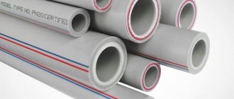
All pipes for heating systems can be divided into two types: metal and polymer.
Metal:
- copper;
- metal-plastic;
- bronze;
- metal corrugated;
- steel.
Copper pipes are superior to all others in the following parameters: long service life, smoothness, which increases the speed of coolant movement, and resistance to ultraviolet radiation.
Polymer:
- polyvinyl chloride (PVC);
- polyethylene terephthalate (PET);
- metal-plastic;
- polyurethane;
- propylene;
- polypropylene.
The cross-sectional diameter in which propylene and polypropylene pipes are offered can be in the range of 16-110 mm. The advantages of this material include: relatively low weight, ease of processing and installation work, low price. Long-burning wood stoves for home heating you will find the answer in the link.
The influence of diameter on heating performance
The heating system installation instructions are unlikely to address the issues of pipeline calculation (also find out how to calculate the diameter of a heating pipe).
Meanwhile, when moving through a pipe, the coolant encounters several types of resistance and this must be taken into account when selecting the standard size:
- friction against the walls . Due to this, part of the speed is lost;
- loss of speed when turning . It is impossible to route around the apartment without turning (in addition, there are turns at an angle of 90ᵒ);
- change in diameters . If you try to use different standard sizes when wiring around the apartment, then resistance to flow will also be observed at the junctions of different standard sizes.
Note! Narrowing the diameter of the heating pipe is undesirable. When wiring around the house you need to use the same standard size. An exception is allowed in the case of a large length of the circulation circuit; in this case, it is possible to increase the speed of the coolant by reducing D.
The diagram shows the nature of fluid movement when the pipe narrows
As for the pipeline itself, its main characteristic that affects the movement of the coolant can be called the internal diameter (ID). The smaller it is, the greater the pressure and vice versa - with increasing pressure, the pressure in the system drops. This must be taken into account when selecting the diameter of the heating pipe.
A common mistake made by amateur plumbers is associated with this phenomenon. They are confident that if they take a larger size, then more coolant will pass through the radiators and the room will warm up faster.
In fact, the effect will be the opposite - due to the drop in pressure, the batteries will remain cool. In this case, installing a more powerful circulation pump can help out, but the price of such a solution is high; it is much easier to choose the right diameter.
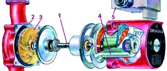
In the photo - circulation pump


