Pros of the Valtec system
Specification of Valtec mixing unit for heated floors
Before starting installation and selecting a mixing unit for a Valtec heated floor, it is necessary to analyze the advantages of this type of water circuit.
- Thanks to high-quality materials and durable fasteners, reliable operation is ensured.
- Developed in the form of modules, the components fit together precisely, eliminating the risk of leaks.
- The manufacturer has provided for the production of related materials necessary for thermal and waterproofing equipment.
Calculation instructions
In order to correctly develop a project for laying a heated floor, you will need a preliminary calculation of the main indicators, focusing on their average values.
Do-it-yourself installation of water heated floors
Various factors have to be taken into account, including the role of the water floor as the main type of heating or its use as an additional heat source. Since detailed calculations for independent implementation are a complex process, in practice average parameters are used.
Valtec mixing unit connection diagram
- The rated power has limits of 90 - 150 W/m2. Higher values are selected for rooms with high humidity levels.
- When calculating the laying step, you need to focus on the range of 15–30 cm. The specific heating power is in inverse proportion to this indicator. That is, the larger the step, the less power.
Thermomechanical diagram of a pumping and mixing unit - Despite the fact that with a large diameter of pipes, a larger amount of coolant passes through them, the limiter of this indicator is the thickness of the screed, which is not recommended to be too large, so as not to create excessive load on the floor. Therefore, Valtec pipes are taken into account, made of modern cross-linked polyethylene with an anti-diffusion coating, with a diameter of 16 to 20 mm, and Valtec press fittings are used as connecting parts.
Once the key parameters have been determined, a diagram can be developed in which the most efficient pipe laying is determined on an exact scale. After this, their total length is calculated. At the same time, it is thought through where the pumping and mixing unit and control elements will be located.
Key characteristics of the mixing unit
In order for the installed water circuit to function effectively, it is necessary to correctly calculate the entire system and correctly install the mixing unit for the Valtec heated floor in accordance with the provisions reflected in the instructions included with the kit.
Connection diagram of the mixing unit to different types of heating
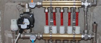
Parameters of the pumping and mixing unit:
- the cross-section of the pipes is ¾ inch, the collectors are 1 inch;
- the design contains 12 pipes;
- the pumping system is 18 cm long;
- the temperature of the heated water in the system is maintained up to 90°C;
- maximum pressure value – 10 bar;
- throughput – 2.75 m3/h.
Specification of Valtec pumping and mixing unit
The pipes have an external thread with a Eurocone connection.
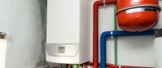
Pumping and mixing unit for heated floors
Functionality
The main purpose of the pumping and mixing unit is to stabilize the temperature of the coolant when entering the water circuit by using water from the return line for mixing. This ensures optimal functioning of the heated floor without overheating.
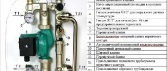
The Combi unit design includes the following service elements:
- drain valves;
- air vents;
- thermometers.
Operating principle of the Combi unit
The following organs are used to adjust the unit:
It is permissible to connect an unlimited number of heated floor branches with a total power of no more than 20 kW to the VALTEC COMBIMIX node
- a balancing valve on the secondary circuit, which ensures mixing in the required proportion of coolants from the supply and return pipelines to ensure the standard temperature;
- balancing shut-off valve on the primary circuit, responsible for supplying the required amount of hot water to the unit. It allows you to completely shut off the flow if necessary;
- a bypass valve that allows you to open an additional bypass to ensure the pump operates in a situation where all control valves are closed.
The connection diagram has been developed taking into account the possibility of connecting to the pumping and mixing unit the required number of floor heating branches with a total water consumption not exceeding 1.7 m3/h. The calculation shows that a similar amount of coolant flow with a temperature difference of 5°C corresponds to a power of 10 kW.
In the case of connecting several branches to the mixing unit, it is advisable to select collector blocks from the Valtec line with the designation VTc.594, as well as VTc.596.
Setting up the VALTEC COMBIMIX pumping and mixing unit
The VALTEC COMBIMIX (VT.COMBI) pump and mixing unit is designed to maintain a given temperature of the coolant in the secondary circuit (due to mixing from the return line). Using this unit, it is also possible to hydraulically link an existing high-temperature heating system and a low-temperature underfloor heating circuit. In addition to the main control elements, the unit also includes the entire necessary set of service elements: an air vent and a drain valve, which simplify the maintenance of the system as a whole. Thermometers make it easy to monitor the operation of the unit without the use of additional devices and tools.
It is permissible to connect an unlimited number of heated floor branches with a total power of no more than 20 kW to the VALTEC COMBIMIX node. When connecting several branches of a heated floor to a node, it is recommended to use VALTEC VTc.594 or VTc.596 collector blocks.
The main adjustment elements of the pumping and mixing unit:
1. Balancing valve of the secondary circuit (position 2 in the diagram).
This valve ensures mixing of the coolant from the return collector of the heated floor with the coolant from the supply pipeline in the proportion necessary to maintain the specified temperature of the coolant at the outlet of the COMBIMIX unit.
The valve setting is changed using a hex wrench; to prevent accidental rotation during operation, the valve is secured with a clamping screw. The valve has a scale with valve throughput values Kvτ from 0 to 5 m3/h.
Note: Although the valve capacity is measured in m3/h, it is not the actual coolant flow rate passing through this valve.
2. Balancing shut-off valve of the primary circuit (pos. 
Using this valve, the required amount of coolant is adjusted that will flow from the primary circuit to the unit (unit balancing). In addition, the valve can be used as a shut-off valve to completely shut off the flow. The valve has an adjusting screw with which you can set the valve capacity. The valve is opened and closed using a hex key. The valve has a protective hex cap.
3. Bypass valve (item 7)
During operation of the heating system, a mode may arise when all control valves of the heated floor are closed. In this case, the pump will operate in a muted system (without coolant flow) and will quickly fail. In order to avoid such modes, there is a bypass valve on the unit, which, when the valves of the underfloor heating system are completely closed, opens an additional bypass and allows the pump to circulate water through a small circuit in idle mode without loss of functionality.
The valve is activated by the pressure difference created by the pump. The pressure difference at which the valve opens is set by turning the regulator. There is a scale on the side of the valve with a range of 0.2–0.6 bar. Pumps recommended for use with COMBIMIX have a maximum pressure of 0.22 to 0.6 bar.
After the heating system is completely assembled, pressure tested and filled with water, it should be adjusted. The adjustment of the control unit is carried out together with the commissioning of the entire heating system. It is best to adjust the unit before starting to balance the system.
Algorithm for setting up the control unit:
1. Remove the thermal head (1) or servo drive.
To ensure that the control valve actuator does not affect the assembly during adjustment, it must be removed.
2. Set the bypass valve to the maximum position (0.6 bar).
If the bypass valve is triggered while the unit is being configured, the setup will be incorrect. Therefore, it should be set to a position in which it will not work.
3. Adjust the position of the secondary circuit balancing valve (item 2 in the diagram).
The required capacity of the balancing valve can be calculated independently using a simple formula:
t1 – coolant temperature on the supply pipeline of the primary circuit;
t11 – temperature of the coolant on the supply pipeline of the secondary circuit;
t12 – coolant temperature in the return pipeline (both circuits are the same);
Kvτ is the control valve capacity coefficient; for COMBIMIX it is assumed to be 0.9.
Calculation example
Initial data: design temperature of the supply coolant – 90 °C; design parameters of the heated floor circuit are 45–35 °C.
The resulting Kv value is set on the valve.
4. Set the pump to the required speed.
To do this, you need to calculate the water flow in the secondary circuit and the pressure loss in the circuits after the unit using the formulas:
G2 = 3600 · Q / s · (t11 – t12), kg/h;
ΔPн= ΔPс + 1, m water. Art.,
where Q is the sum of the thermal power of all loops connected to COMBIMIX; c – heat capacity of the coolant (for water – 4.2 kJ/kg °C; if a different coolant is used, the value should be taken from the data sheet of this liquid); t11, t12 – temperature of the coolant in the supply and return pipelines of the circuit after the COMBIMIX unit. ΔPс – pressure loss in the design circuit of the heated floor (including collectors). This value can be obtained by performing a hydraulic calculation of the heated floor. To do this, you can use the calculation program VALTEC.PRG.
Using the pump nomograms presented below, we determine the pump speed. To determine the pump speed, a point with the corresponding pressure and flow rate is marked on the characteristic. Next, the nearest curve above this point is determined, and it will correspond to the required speed.
Example
Initial conditions: underfloor heating with a total power of 10 kW, pressure loss in the most loaded loop of 15 kPa (1.53 m of water column).
Water flow in the secondary circuit:
G2 = 3600 · Q / s · (t11 – t12) = 3600 · 10 / 4.2 · (45 – 35) = 857 kg/h (0.86 m3/h).
Pressure losses in the circuits after the COMBIMIX unit with a reserve of 1 m of water. Art.:
ΔPн= ΔPс + 1 = 1.53 + 1 = 2.53 m water. Art.
Selected pump speed – MED at point (0.86 m3/h; 4.05 m water column):
If it is not possible to calculate the pump, then you can skip this step and proceed directly to the next one. At the same time, set the pump to the minimum position. If during the balancing process it turns out that there is not enough pump pressure, you need to switch the pump to a higher speed.
5. Balancing the branches of a heated floor.
Close the balancing shut-off valve of the primary circuit. To do this, open the valve cover and use a hex wrench to turn the valve counterclockwise until it stops.
The task of balancing heated floor branches comes down to creating the required coolant flow in each branch and, as a result, uniform heating.
The branches are balanced with each other using balancing valves or flow regulators (not included in the COMBIMIX kit; flow regulators are included in the VTc.596.EMNX manifold block). If there is only one circuit after COMBIMIX, then nothing needs to be linked.
The balancing process is as follows: balancing valves/flow regulators on all branches of the heated floor are opened to the maximum, then a branch is selected in which the deviation of the actual flow from the design one is maximum. The valve on this branch closes to the required flow rate. Thus, it is necessary to adjust all the branches of the heated floor.
When adjusting the VT.FLC15.0.0 flow regulators, you simply need to set the desired flow rate on the scale in l/min by turning the knob. If it is not possible to use a flow indicator, then you can balance the branches approximately by heating the floors or by the temperature of the return coolant.
If during the balancing process it was not possible to obtain the required flow rate through the branches even with the valves open, this means that the hydraulic calculation was performed incorrectly and the pump should be switched to a higher speed.
Setting the primary circuit balancing valve
The balancing valve of the primary circuit is adjusted together with the balancing of the rest of the heating system. The essence of balancing a heating system is to adjust the coolant flow through each heating device, including COMBIMIX, exactly according to the design. If heating systems are not balanced correctly, the system may operate when some of the heating devices are overheated and some are not warmed up enough.
Consider the following diagram of a heating system with a connected COMBIMIX node. This is a two-pipe dead-end heating system with horizontal wiring.
Below the diagram is a piezometric graph. The graph shows the pressure drop in the heating system with green slanted lines. The device located closest to the boiler (or individual heating point) has a greater pressure drop between the forward and return pipelines (vertical lines) than the device located at the end of the system. The orange color on the vertical lines shows the pressure drop across the devices without taking into account the balancing valves, the green color shows the pressure drop that must be created across the valve in order to balance the system. The higher the pressure drop across the device, the greater the flow rate passes through it at the same throughput. In order to equalize the coolant flow in the system, it is necessary to add resistance to devices that are closer to the boiler using balancing valves or control valves. The closer the device is to the boiler, the more resistance must be added using the valve (more valve closing). The graph shows that the valve of the first device is closed so much that its resistance is several times higher than the resistance of the radiator. With the latter device, the valve is practically open and its resistance is low.
Balancing, as a rule, comes down to finding the desired setting of the balancing valves. There are three main ways to perform balancing.
The calculation method consists in the fact that when hydraulically calculating a heating system, a similar piezometric graph is drawn up for the designed heating system. During the hydraulic calculation, the required pressure loss at each balancing valve is determined. Next, the following formula determines the valve capacity:
kv = V /√ΔP, m3/h,
where V is the volumetric flow rate of the coolant, m3/h; ΔP – required pressure loss across the valve, bar.
After calculating the capacity according to the recommendations of the balancing valve manufacturers, the adjuster sets the design capacity value on each valve. Hydraulic calculations must be carried out by a qualified specialist manually or using specialized programs, for example the VALTEC.PRG engineering systems calculation program.
Example
First, let's determine the required coolant flow in the primary circuit. To do this, you can use the following formula:
G2 = 3600 Q /c (t1 – t2),
where Q is the sum of the thermal power of all devices connected after COMBIMIX; c – heat capacity of the coolant (for water – 4.2 kJ/kg °C; if a different coolant is used, the value should be taken from the data sheet of this liquid); t1, t2 – temperature of the coolant in the supply and return pipelines of the primary circuit (the temperatures of the coolant in the return pipeline of the primary and secondary pipelines are the same).
For a heated floor with a total power of 10 kW with a design temperature of the supply coolant of 90 °C, design parameters of the heated floor circuit of 45–35 °C, the coolant flow in the primary circuit will be as follows:
G2 = 3600 · Q /c · (t1 – t2) = 3600 · 10 / 4.2 · (90 – 35) = 155.8 kg/h.
When calculating, the designer determined that the pressure loss on the balancing valve of the unit should be 9 kPa (0.09 bar), in order for the coolant flow in the primary circuit to be 0.159 m3/h, the kv of the valve should be:
kv = 0.159 /√0.09 = 0.53 m3/h.
Next, according to the characteristics of the balancing valve of the primary circuit given below, the number of turns of the adjusting screw is determined.
To determine the number of revolutions, you can not count kv but use the nomogram given below. To do this, plot the required flow through the primary circuit and the required pressure loss across the valve on the graph. The nearest inclined line will correspond to the required setting (number of revolutions). To improve accuracy, you can interpolate the obtained values.
The first line of the table indicates the position, the second line of the table indicates the number of turns of the adjusting screw. (In this example, 2 and ¼.) The third line shows Kv for this setting, as you can see it practically coincides with the calculated one.
Setting the valve speed:
The correct adjustment of the valve should start from the position of the valve being fully closed; using a thin flat-head screwdriver, tighten the adjusting screw until it stops and put a mark on the valve and on the screwdriver.
Using the valve setting table, turn the screw the required number of revolutions. To fix the speed, use the marks on the valve and screwdriver. (following the example, you need to make 2 and ¼ turns).
Using a hex key, open the valve until it stops. The valve will open exactly as much as you turn the screwdriver. After setting the valve, you can open and close it using a hex wrench, while maintaining the capacity setting.
In the same way, all other balancing valves of the heating system are calculated. The number of valve revolutions (or the setting position is determined according to the methods of balancing valve manufacturers).
The second way to balance the system is that the settings of all valves are set “in place”. In this case, the setting values are determined based on the actually measured coolant flow rates for individual branches or systems.
This method is used, as a rule, when setting up large or critical heating systems. During balancing, special devices are used - flow meters, with which you can measure flow in individual directions without opening the pipeline. Balancing valves with fittings and special pressure gauges are also often used to measure the pressure drop, which can also be used to determine the flow rate in individual areas. The disadvantage of this method is that instruments designed to measure flow are too expensive for one-time or infrequent use. For small systems, the cost of the devices may exceed the cost of the heating system itself.
When balancing using this method, COMBIMIX is configured as follows:
Fix the flow meter on the pipeline through which COMBIMIX is connected to the heating system. Calibrate and configure the flow meter according to the instructions for the flow meter.
Then smoothly open the balancing valve using a hex wrench, while recording the change in coolant flow. As soon as the coolant flow corresponds to the design, fix the position of the valve using the adjusting screw.
Example
As for the previous example, the coolant flow rate is first calculated.
For a heated floor with a total power of 10 kW, a design temperature of the supply coolant of 90 °C, and design parameters of the heated floor circuit of 45–35 °C, the coolant flow in the primary circuit will be as follows:
G2 = 3600 · Q /c · (t1 – t2) = 3600 · 10 / 4.2 · (90 – 35) = 155.8 kg/h (0.159 m3/h).
Close the balancing valve completely using the hexagon:
Smoothly open the valve using a hexagon and record the flow rate on the flow meter until the flow rate reaches the design value (in the example, 0.159 m3/h).
After the coolant flow has been established, fix the position of the shut-off valve using the adjusting screw (tighten the adjusting screw clockwise until it stops).
After the adjusting screw is fixed, the valve can be opened and closed using a hexagon, the setting will not be lost.
For small systems in the absence of a design and complex measuring instruments, the following balancing method is acceptable:
In the finished system, turn on the boiler and central pump (or other heat supply source), then close all balancing valves on all heating devices or branches. After this, the heating device that is installed furthest from the boiler (heat supply source) is determined. The balancing valve in this device opens completely; after the device has completely warmed up, it is necessary to measure the temperature difference of the coolant before and after the device. Conventionally, we can assume that the temperature of the coolant is equal to the temperature of the pipeline. Then we move on to the next heating device and smoothly open the balancing valve until the temperature difference between the forward and return pipelines coincides with the first device. Repeat this operation with all heating devices. When the turn comes to the COMBIMIX unit, its adjustment should be carried out as follows: If the coolant temperature in the supply pipeline is equal to the design one, then the balancing valve of the primary circuit should be smoothly opened until the readings on the thermometers of the supply and return pipelines of the secondary circuit are equal to the design ± 5 °C.
If the temperature of the coolant in the supply pipeline during setup of the system differs from the design one, then the following formula can be used for recalculation:
where temperatures with the index “P” are design, and temperatures with the index “N” are adjustment (used for adjustment) values.
Example
Consider the following heating system:
To begin with, all balancing valves are closed.
The heating device that is furthest from the boiler is selected. In this case, it is the rightmost radiator. The radiator balancing valve opens completely. After the radiator has warmed up, the temperature of the forward and return pipelines is recorded.
For example, after opening the valve, the temperature in the supply pipeline was 70 °C, the temperature in the return pipeline was 55 °C.
Then a second device is taken at a distance from the boiler. The balancing valve on this device opens until the temperature in the return pipeline is equal to the temperature of the first ±5 °C.
COMBIMIX setting: design temperature of the supply coolant – 90 °C; design parameters of the heated floor circuit are 45–35 °C. Actual readings taken from thermometers: supply coolant temperature – 70 °C.
Using the formula, we determine the temperature of the coolant in the supply pipeline of the secondary circuit:
We determine the temperature of the coolant in the return pipeline of the secondary circuit:
We open the balancing valve of the secondary circuit until the temperatures on the COMBIMIX thermometers coincide with the calculated ones ± 5 ° C.
Fix the position of the shut-off valve using the adjusting screw (tighten the adjusting screw clockwise until it stops). After the adjusting screw is fixed, the valve can be opened and closed using a hexagon, the setting will not be lost.
Next, configure all remaining balancing valves in the same way.
Bypass Valve Setting
There are two ways to set the bypass valve:
- If the resistance of the most loaded branch of the heated floor is known, then this value should be set on the bypass valve.
2. If the pressure loss on the most loaded branch is unknown, then the bypass valve setting can be determined from the pump characteristics.
The valve pressure value is set to 5–10% less than the maximum pump pressure at the selected speed. The maximum pump pressure is determined by the pump characteristics.
The bypass valve should open when the pump approaches a critical point, when there is no water flow and the pump works only to build up pressure. The pressure in this mode can be determined from the characteristic.
An example of determining the setting value of a bypass valve.
In this example, it can be seen that the pump, in the absence of water movement at first speed, has a pressure of 3.05 m of water. Art. (0.3 bar), point 1; at average speed - 4.5 m water. Art. (0.44 bar), point 2; and at a maximum of 5.5 m water. Art. (0.54 bar), point 3.
Since the pump is set to medium speed, we select the setting on the bypass valve 0.44 - 5% = 0.42 bar.
6. Final stage
After setting up all the components of the COMBIMIX unit, you should put back the thermal head of the control valve and make sure that the control valve is working. Close the cover of the primary circuit balancing valve. The unit is ready for use.
Setting up heating systems is one of the most difficult engineering tasks. The VALTEC COMBIMIX pump and mixing unit allows you to simplify this task. This unit is a ready-made comprehensive solution for organizing a heated floor circuit in heating systems. A well-thought-out configuration of the unit allows you to eliminate errors when designing a particular system. The flexibility of the unit setup allows you to set up underfloor heating systems without the use of special devices.
*article taken from the website VALTEC.ru
Installation algorithm
After the preliminary calculation of all components has been completed, the actual installation of the heated floor begins, which involves going through several stages.
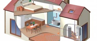
Scheme of water floor heating
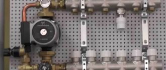
- Installation at a pre-selected location of the manifold cabinet. It contains a module consisting of a collector block and a pumping and mixing unit with ball valves, through which the connection to the high-temperature circuit will be made.
- Preparing the floor plane. If there are significant irregularities, measures are taken to eliminate them. The most effective option is a rough screed.
Connection diagram of the pumping and mixing unit to the heated floor - Fixation around the perimeter of a damper tape, which serves as an element that compensates for the possible expansion of the screed that occurs when it is heated. It is attached to the walls so that after finishing the excess remains, which is cut off before installing the plinth.
- Thermal insulation equipment by laying polystyrene foam boards with mounting bosses on a leveled floor, under which waterproofing is laid if necessary.
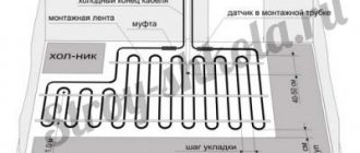
- A previously developed diagram serves as a guide for the subsequent layout of pipes.
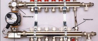
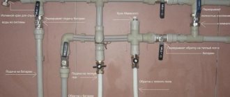
How to assemble a collector?
The Valtec distribution block is manufactured assembled. Flow meters are already installed on the hot tube. There are thermal heads on the cold line, but the product may only have outputs for attaching temperature control devices. They are protected by plastic caps. The manufacturer gives you the opportunity to choose which automation to install: thermal head, servo drive.
Some small elements need to be connected to the collector group:
- On the right, shut-off valves are connected to the tubes. There are 2 of them in the set.
- A float device is connected to the valves to remove air.
- Opposite the air vents, drain valves are connected to the underside of the tubes.
- The ends of the comb are closed with plugs.
We recommend: How to install electric heated floors under tiles?
A circulation pump and a three-way or two-way valve are separately connected to the comb. These devices must be purchased separately. They are connected on the left to the tube into which the cold coolant flows. Use brass threaded fittings.
The cold and hot circuits are removed from metal pipes that are connected to the boiler or furnace. They are connected via a bypass at the outlet of the collector group. A circulation pump with a temperature sensor is installed between the circuits.
The rotameter is adjusted when testing the heating system. The protective sleeve must be removed from the device. Using the red ring, the upper bushing, set the rotameter to zero.
Next, using the same bushing, install the valve on the o for large rooms, on the o for small rooms. To fix the rotameter parameters, turn the lower ring to the right until it stops.
Return the protective cap to its original place. The rotameter may not have a locking ring. In this case, the pipeline fill indicator is set without fixing. Valve operation must be checked regularly.
Valtek collectors for heated floors are installed with a liquid heating system. The coolant can be water, antifreeze, glycol fillers that do not freeze at low temperatures. If the heating system is not used, then the coolant does not need to be drained.
The number of circuits on the distribution block is 3-12 pcs. If necessary, additional equipment can be connected to them to increase the flow capacity of the coolant to all rooms in the house.
The comb is mounted on the wall or placed in a manifold cabinet. The manufacturer provides a 10-year warranty on the equipment. Service centers are located in St. Petersburg and Moscow. The block will last more than 50 years.
If necessary, the rotameter or thermal head can be replaced without turning off the heating system. When using a programmable thermostat, the operation of the heated floor control unit can be carried out through electronic gadgets.
We recommend: How to install heated floors under PVC?
YouTube responded with an error: The request cannot be completed because you have exceeded your quota.
- Related Posts
- How is a heated floor connected?
- What is film heated flooring?
- How to make a warm floor?
- Which pipes are best to choose for heated floors?
- What is a mobile heated floor?
- How to choose tile adhesive for underfloor heating?
Settings
To connect pipes to distribution manifolds, a pipe cutter is used to cut the required length, a calibrator, a chamfer and a compression fitting. It is difficult to carry out detailed calculations at home, so be sure to study the instructions, which detail the settings of the pumping and mixing unit in a certain sequence.
- The thermal head is removed.
- For a balancing valve on the secondary circuit, the capacity is calculated using the formula.
Two mixing unit options
kνb = kνt {[(t1 – t12) / (t11 – t12)] – 1},
where kνt – coefficient = 0.9 valve capacity;
t1 – supply water temperature of the primary circuit, °C;
t11 – temperature of the secondary circuit at the coolant supply, °C;
t12 – return pipeline water temperature, °C.
The calculated kνb value must be set on the valve.
- Setting the desired operating mode of the bypass valve when setting the maximum pressure difference to 0.6 bar.
- In order for the heated floor to function effectively, the required pump speed is adjusted. To do this, it is necessary to determine the value of the coolant flow rate in the secondary circuit system, as well as the pressure loss that appears in the circuits located after the unit.
Equipment for Valtec mixing unit
Flow rate G2 (kg/s) is determined by the formula:
G2 = Q / [4187 • (t11 – t12)],
where Q is the total thermal power of the water circuit connected to the mixing unit, J/s;
4187 [J/(kg•°С)] – heat capacity of water.
To calculate pressure losses, a special hydraulic calculation program is used. To determine the pump speed, which is set using a switch, according to the calculated indicators, a nomogram is used, which is in the instructions attached to the heated floor design.
Connection diagram for heated floor circuits
- Operations are being performed to adjust the balancing valve on the primary circuit.
- The thermostat sets the temperature required for comfortable heating.
- A trial run of the system is being carried out.
If there are no leaks, all that remains is to make a concrete screed, and after it has completely hardened, lay the flooring.
Features of setting up a Valtec manifold without flow meters
If the manifold is not equipped with flow meters, but only with valves, you will have to set the flow rate by touch. This is not figurative, but literally. Knowing the length of each circuit, we open the flow to the maximum on the longest one. We screw the rest approximately. You can count the number of valve revolutions and focus on them.
Manifold for underfloor heating without flow meters
Next, we turn on the heating and wait until the floor warms up. If you have a thermometer, measure the floor temperature in the operating area of each circuit. There is no thermometer - we feel and compare sensations. Based on the results, we adjust the position of the valves and wait again for several hours. We continue this way until we are satisfied with the result. In principle, a Valtec manifold with valves without a flow meter is not that difficult to configure.
Evaluating collector settings based on return temperature
This check is based on the fact that with a correctly adjusted flow rate, the return temperature on all circuits should be the same. To set up or check this type, you need special thermometers. They are installed on the return pipeline between the manifold inlet and the pipe.
You can adjust the collector using a return thermometer
The temperature of the longest circuit is taken as a reference - all the others are adjusted to it. Only the adjustment results will need to be corrected after a few hours. When the floor heated by adjustable circuits warms up or cools down (depending on the adjustment) and the temperature in the return pipe changes again. It will take several such adjustments until the difference becomes insignificant.