Making a solar collector for alternative heating in your home
Recently, the interest of ordinary people in renewable energy sources has increased.
Because of this, many homeowners are looking to buy a solar collector for home heating, which converts the sun's energy to heat water. But the decision to buy a solar collector for heating in a store is not always rational. The cost of the finished device is far from budget, so such a purchase can hit the family budget hard. To avoid expenses, you can make a solar vacuum collector for heating yourself. Various solar collectors for home heating, reviews of which are positive, have the following design details:
- container for storing heated water;
- heat exchanger;
- device for collecting solar energy;
- insulating layer.
The materials from which the collector can be made are very diverse.
There are known technologies for the independent production of solar collectors from polypropylene, ordinary garden hoses, window frames, plastic bottles, old refrigeration units and other available materials. The collector assembly diagram directly depends on the type of material chosen, so it is worth studying after the owner has decided on the concept of the collector. Self-made vacuum solar collectors for home heating, the price of which in the store is $200 or more, can be used as full-fledged heating sources.
Vacuum solar collectors have a number of advantages:
- energy efficiency;
- environmental friendliness;
- autonomy;
- availability.
It is not difficult to make traditional distribution or solar collectors for heating your home with your own hands. This does not require large material costs, complex technological equipment or solid experience. However, these hand-made devices will greatly optimize the home heating system and will help the owner create a reliable, efficient and uniform source of heating for his home.
Solar collector - an opportunity to save
It is possible to connect several coolant heating sources to the heating circuit. Often solid fuel boilers operate in parallel with electric ones, this makes it possible to maintain the operating mode of the heating system at night or in the absence of owners for several days.
But this mode cannot be called economical - electricity is one of the most expensive resources. Modern developments make it possible to use solar energy to heat the coolant by installing a solar collector.
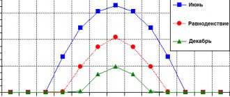
A solar collector is an installation that can be used all year round, even in cloudy temperatures . On sunny days it is most effective and heats up to the temperature of the boiler supply circuit - up to 70-90 degrees.
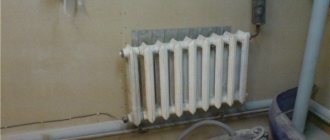
Homemade solar collector
A solar collector is a fairly simple device; it is not difficult to make it yourself. In terms of efficiency, a homemade solar water heater may be inferior to industrial models, but given their price - from 10 to 150 thousand rubles, a solar collector made by yourself will very quickly pay for itself.
To make it you need:
- a coil made of a metal tube, usually copper, you can take a suitable one from an old refrigerator;
- scraps of copper pipe with a 16 mm thread on one side;
- plugs and valves;
- pipes for connection to the collector unit;
- storage tank with a volume of 50 to 80 liters;
- wooden planks for making a frame;
- sheet of expanded polystyrene 30-40 mm thick;
- glass, you can take window glass;
- thick aluminum foil.
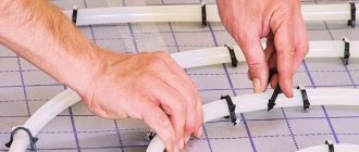
The coil is freed from freon residues by washing it with a stream of running water. A frame with a size slightly larger than a coil is made from a wooden lath or block. Holes are drilled in the lower part of the frame to remove the coil tubes.
On the reverse side, a sheet of polystyrene foam is attached to it with glue or self-tapping screws - this will be the bottom of the collector. This material has excellent thermal insulation characteristics, which will help reduce heat loss.
Foil is placed from the inside so that it completely covers the bottom and walls of the frame. The foil is attached to the staples using a stapler. The coil is placed in the frame, its ends are threaded into the hole.
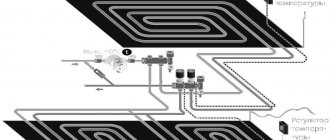
The top of the solar collector is covered with glass, securing it to glazing beads or slats. Pipes are attached to the ends of the coil for connection to the heating manifold unit. This can be done using adapters or flexible liners.
The collector is placed on the southern slope of the roof. The pipes lead to a storage tank equipped with an air valve, and from there to the heating distribution manifold.
Video: how to make your own solar heater
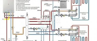
A manifold heating system is the most efficient way to connect different heaters to one or more heating sources . With its help, you can ensure stable temperature and comfort in the house, as well as uninterrupted and coordinated operation of all elements of the system.
What is it needed for
When installing water pressure systems, there is a rule: the total diameter of all branches should not exceed the diameter of the supply pipe. In relation to heating equipment, this rule looks like this: if the diameter of the boiler outlet fitting is 1 inch, then the system allows two circuits with a pipe diameter of ½ inch. For a small house heated only with radiators, such a system will work effectively.
In fact, there are more heating circuits in a private house or cottage: heated floors. heating of several floors, utility rooms, garage. When they are connected through a tapping system, the pressure in each circuit will be insufficient to effectively heat the radiators, and the temperature in the house will not be comfortable.
Therefore, branched heating systems are made using collector systems; this technique allows you to adjust each circuit separately and set the desired temperature in each room. So, for a garage, plus 10-15ºС is enough, and for a nursery, a temperature of about plus 23-25ºС is required. In addition, heated floors should not heat up more than 35-37 degrees, otherwise it will be unpleasant to walk on them, and the floor covering may become deformed. With the help of a manifold and shut-off temperature, this problem can also be solved.
Video: using a collector system for heating a house.
Manifold groups for heating systems are sold ready-made, and they can have different configurations and the number of outlets. You can select a suitable collector assembly and install it yourself or with the help of specialists.
However, most industrial models are universal and do not always fit the needs of a particular home. Redesigning or modifying them can significantly increase costs. Therefore, in most cases it is easier to assemble it from separate blocks with your own hands, taking into account the characteristics of a particular heating system.
Manifold group for heating system assembly
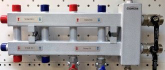
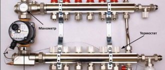
The design of the universal collector group is shown in the figure. It consists of two blocks for forward and reverse coolant flow, equipped with the required number of outlets. Flow meters are installed on the supply (direct) manifold, and thermal heads are located on the return manifold to regulate the return water temperature in each circuit. With their help, you can set the required coolant flow rate, which will determine the temperature in the heating radiators.
The manifold distribution unit is equipped with a pressure gauge, circulation pump and air valves. The supply and return manifolds are combined into one unit with brackets, which also serve to attach the unit to a wall or cabinet. The price of such a block is from 15 to 20 thousand rubles. and if some of the taps are not used, its installation will be clearly impractical.
The rules for installing the finished block are shown in the video.
Comb - collector unit
The most expensive elements in a manifold distribution block are flow meters and thermal heads. To avoid overpaying for unnecessary elements, you can buy a collector unit, the so-called “comb”, and install the necessary control devices with your own hands only where necessary.
The comb consists of brass tubes with a diameter of 1 or ¾ inches with a certain number of taps with a diameter of ½ inch for heating pipes. They are also connected to each other by a bracket. The outlets on the return manifold are equipped with plugs that allow you to install thermal heads on all or part of the circuits.
Some models may be equipped with taps, with their help you can regulate the flow manually. Such combs have a cast body and are equipped with a fitting/nut thread at the ends, which allows you to quickly and easily assemble a manifold from the required number of branches.
In order to save money, the manifold for heating systems can be assembled from individual elements independently or completely made by hand.
Do-it-yourself heating manifold for polypropylene pipes: we explain the essence
The defining task when designing an autonomous heating system is the uniform distribution of the coolant. The complex of thermal engineering measures for organizing not only a productive, but also a reliable heating line includes the arrangement of such a control and regulatory unit.
If you wish and follow the nuances, you can assemble a heating distribution manifold with your own hands or simply pay for a ready-made option.
The role of the collector in heating
When arranging a water pumping unit, you must adhere to the rule: the total sum of the diameters of all branches should not be greater than the diameter of the supply main.
Let's apply this law to the heating system, but it will look like this: a boiler outlet fitting with a diameter of 1 inch is allowed for use in a double-circuit system with pipes with a diameter of ½ inch.
For a house with a small cubic capacity that is heated exclusively by radiators, this kind of system is considered productive.
For utility rooms, it will be enough to set the temperature to 10-15 °C; for living rooms, a temperature of up to 23 °C will be comfortable; in underfloor heating circuits – no more than 37 °C, otherwise the main coating may be deformed.
In practice, a private cottage is equipped with a more modernized heating circuit, where additional circuits are installed:
- heated floor system;
- heating of several floors;
- utility rooms, etc.
When a branch is connected, the level of operating pressure in the circuits becomes insufficient for high-quality heating of all radiators, respectively, and the comfortable atmosphere will be disrupted.
In this case, a balancing unit is installed for a branched heating main using a distribution manifold. Using this method, it is possible to compensate for the cooling of the heated coolant, which is typical of traditional one- and two-pipe schemes.
By means of equipment and shut-off valves, the required coolant temperature indicators are adjusted for each of the lines.
Main characteristics of the collector system
The main difference between the collector and standard linear method of redistribution of the coolant is the division of flows into several channels independent of each other. Various modifications of collector installations can be used, differing in configuration and size range.
The collector heating circuit is often called radiant. This is due to the design features of the comb. When examining the device from the top point, you will notice that the pipelines extending from it resemble an image of sun rays
The design of the welded manifold is quite simple. The required number of pipes is connected to the comb, which is a round or square pipe, which, in turn, are connected to individual lines of the heating circuit. The collector installation itself is interfaced with the main pipeline.
Shut-off valves are also installed, through which the volume and temperature of the heated liquid in each of the circuits is regulated.
A manifold group, complete with all the necessary parts, can be purchased ready-made or assembled independently, which will significantly reduce the cost estimate when designing heating
The positive aspects of operating a heating system based on a distribution manifold are the following:
- The centralized distribution of the hydraulic circuit and temperature indicators occurs evenly. The simplest model of a two- or four-circuit ring comb can balance the indicators quite effectively.
- Regulation of heating main operating modes. The process is reproduced due to the presence of special mechanisms - flow meters, mixing unit, shut-off and control valves and thermostats. However, their installation requires correct calculations.
- Ease of maintenance. The need for preventive or repair measures does not require shutting down the entire heating network. Due to the sliding pipeline fittings mounted on each individual circuit, you can easily shut off the coolant flow in the required area.
However, there are also disadvantages to such a system. First of all, pipe consumption increases. Compensation for hydraulic losses is carried out by installing a circulation pump. It must be installed on all collector groups. In addition, this solution is only relevant in closed-type heating systems.
Modifications of collector units
Before you begin assembling the collector assembly, it is necessary to determine its functional load. The equipment can be installed in several sections of the heating main. Based on this, the necessary equipment, dimensions and level of automation of the work cycle are selected.
In fact, for the full operation of such a node, two devices are needed. Using a comb, the coolant is distributed along the contours of the central supply pipeline. The return collector channel is represented by a collection mechanism and the point of departure of the cooled liquid into the boiler.
The collector heating circuit is selected based on the calculation of the required functionality and installation location. The choice of material for making the device does not affect the number of significant mechanisms
Installation of a homemade distribution group may be required when installing water-heated floors or for preparing standard heating with radiators.
Distinctive features of both options are their sizes and components:
- Boiler room . The welded manifold group is made of pipes with a diameter of up to 100 mm. A circulation pump and shut-off valves are installed on the supply side. The return ring is equipped with shut-off ball valves.
- Warm floor system . Similar equipment is present in this mixing unit. With its help, it is possible to significantly save on coolant consumption, especially if additional flow meters are installed.
Each of these solutions provides an individual installation scheme. Correct installation of all elements can be carried out only after detailed calculations of all operating point parameters.
The comb can be made of the same material as the pipeline. If it is different, adapters will be used to connect the collector
There are also differences in the required number of circulation pumps. In the boiler room, each line is equipped with this device. For heated floors, only one installation is provided.
Distribution node design
There is simply no universal scheme for a radiant heating project. Each case is individual, which is why the unit is equipped with the necessary devices privately. However, it is worth familiarizing yourself with the general recommendations and rules.
Rules for installing the comb
Installation of the collector is not possible in an apartment. However, there is an exception to the rule - in some houses, when all communications are installed, additional valves are installed, through which the heating circuits are connected. This device allows for individual wiring of the collector.
The radial scheme is not suitable for city apartments in multi-storey buildings, since the riser is common to all premises
The schematic arrangement of the heating should be designed in such a way that the location of the Mayevsky tap is on the comb. This option is considered optimal, because over time, accumulated air will need to be released from the circuits.
Features of the beam group
The radial wiring group has many features, but some of them are also typical for heating of another modification:
- The circuit must include a compensation tank with a volume of more than 10% of the total volume of the coolant.
- The optimal location of the expansion tank is on the return pipeline in front of the circulation pump, since the temperature regime is lower here.
- If a thermo-hydraulic distribution is used, the circuit is designed so that the tank is located in front of the main pump, which is responsible for the forced movement of water in the boiler piping.
- The circulation pump is installed in a strictly horizontal position. If you do not adhere to this rule, at the first air lock, the device will lose cooling and lubricant.
The distribution group can be assembled from various materials: polypropylene or metal. The selection is made based on work skills and the availability of tools for connecting parts.
The optimal heating temperature for radiators in a private cottage is 55-75 °C, pressure up to 1.5 atm. The operating mode of the warm floor circuit warms up to 40 °C. Based on these characteristics, the degree of stability of the pipes is selected
The process of selecting pipes for installing a distribution group is also considered important. The main factors taken into account when choosing contour elements:
- Purchase pipes only as a single element - in coils. Due to this, connections are not made in the wiring installed under the concrete screed.
- Heat resistance and tensile strength must be determined individually based on the technical data of the heating system.
Due to the predictability of the operating characteristics of autonomous heating, polypropylene pipes can be used. They do not have unwanted connections and are sold in continuous 200 m lines.
The material is heat-resistant and can withstand temperatures up to 95 °C with a permissible burst pressure of 10 kg/1 cm2.
Stainless steel pipe is highly flexible. The bend radius can be equal to the diameter of the product. Installation is carried out according to the following scheme: the pipe must be directed into the fitting and secured with a nut
For a multi-story building, it is preferable to choose a corrugated pipe made of stainless steel. This material shows excellent technical capabilities to cope with such a load:
- heated coolant up to 100 °C, which is more than enough for the heating circuit;
- pressure up to 15 atm;
- fracture pressure up to 210 kg/1 cm2.
Fittings designed for polypropylene can be plastic or made of brass. The fitting connection is equipped with a locking ring, which is threaded onto the pipeline.
An important characteristic of polypropylene pipes is the memory of mechanical processing, which results in plastic deformation of the substance.
For example, when stretching pipes with an extender and installing a fitting into the connector, after a certain time the pipe will return to its previous state and crimp the part. The contact can be secured with a locking ring.
Heating manifold calculation
Initially, to manufacture a thermohydraulic comb, you will need to calculate its main parameters - length, cross-sectional diameter of the pipes and the number of branches of the heating main. You can calculate these characteristics yourself or use special software.
The hydraulic separator will fully perform its functions only if the rule of three diameters is observed. The law is as follows: the diameter of the mounted hydraulic arrow must be three times greater than this parameter for the pipes
The hydraulic balance of the structure is the main condition that must be met. Applying the rule of three diameters for a hydraulic separator, it is necessary to perform the following action - sum up the cross-sectional diameter of the connected circuits.
As a result, we get an amount equal to the diameter of the main pipe connected to the supply line. Using this principle reduces the likelihood of imbalance of the entire heating system.
A special cabinet or housing is used as a place for the distribution unit. When arranging the system, it is necessary to adhere to the permissible minimum distance between two heat-conducting input and output lines - 6 diameters.
All calculations of the thermohydraulic comb design involve following important rules: maintain the correct distance between the incoming and outgoing lines, make sure that the cross section of the comb and the distance between the circuits are equal to three diameters
The issue of correct selection of the circulation pump performance is also relevant. To do this, it is necessary to calculate the specific rate of water consumption of the system and, based on the results, select a pump. If the circuit is complicated by several combs, the calculation is performed for each individual circuit and in general for the entire system.
Self-assembly of equipment can be carried out using a pipe with any type of cross-section. This aspect does not affect the operation of the device and does not increase local losses. They will be compensated by the circulation pump.
Rules for selecting components
Having completed all the calculations, the next step is to select the required set of mechanisms. The simplest set consists of shut-off valves. However, with such a device it is difficult to regulate the power of individual heating lines.
To solve this problem, crane axle boxes are installed on the feed comb, through which smooth adjustment is possible. Rotameters are mounted on the return manifold.
The collector parameters must be sufficient for convenient access to shut-off and control valves. The average range between the contours is 100-150 mm, the center distance between the feed and return combs is 250-300 mm
For warm water floors, the configuration scheme will be different. For assembly you will need the following elements:
- Shut-off and control valve. Installation is carried out on connecting pipes. With the help of this fittings, the flow of coolant is completely or partially stopped. It is recommended to use automatic modification.
- Rotameters. Such elements are mounted on the return collector. They perform a similar function as the previous element, only in the return pipeline.
- Mixing unit. By mixing hot and cold water flows, the specified heating operating mode is optimized.
The manifold kit is necessarily equipped with a safety group headed by a pressure gauge, air valve, thermostat and circulation pump. It can be supplemented with servo drives, the control of which is reproduced through the control electrical unit. Thus, the operation of the system can be automated.
Subtleties of self-assembly
Before manufacturing the collector, it is necessary to draw up a diagram showing the location of all the elements of the assembly. It is better to choose steel pipes with a square cross-section as the manufacturing material. This type is easy to process, which significantly reduces labor costs for installing pipes.
Manifolds made of profile pipes are used in the heating circuit of objects with a large number of circuits and a hydraulic separator. Square pipe parameters – 80*80 or 100*100 mm
The step-by-step process for producing a prefabricated distribution structure is as follows:
- Marking and cutting of the main body. According to the design diagram, it is necessary to mark the profile pipe. Using a gas cutter, holes are made in the marked areas.
- Preparing connections. The pipes are threaded using a die.
- Staffing. Next, the prepared pipe sections are welded to the body. Their fixation must be done by tack spot welding. Then, during the main welding, the workpieces are welded along the edges.
- Fastening elements. Brackets for fastening are welded to the block.
- Cleaning and finishing. After cleaning, the body is primed and coated with heat-resistant paint for metal products. The supply and return circuits are painted in two different colors for ease of identification.
If polypropylene pipes are used for production, you should pay attention to the presence of a reinforcing layer in them. In its absence, the plastic structure may be subject to deformation due to the current temperature conditions.
For those who do not have special tools, you can assemble a comb from separate ready-made elements. It is better to select components from one company.
Installing a comb in the heating system
The primary task is to check the distribution manifold for tight connections. The installation is implemented according to the design scheme. Depending on the material used to manufacture the main unit, the connection conditions are determined.
In complex systems where there are many circuits for various purposes, it is necessary to install a vertical pipe - a hydraulic arrow. With its help, pressure equalization and distribution of forward and reverse flows of coolant are realized
The choice of connection technology depends entirely on the modification of the device used.
In addition to maintaining the level, during installation you must follow the following rules:
- electric and gas boilers are connected to the upper or lower pipes;
- a circulation pump is mounted at the end of the structure;
- the circuits can be connected at the top or bottom of the comb;
- indirect heating devices and boilers operating on solid fuel must be connected to the distribution group on the side;
- the entire hydraulic separation unit for the underfloor heating system is placed in a protective box - this reduces the risk of damage to the constituent elements of the collector.
At the final stage, it is necessary to carry out a control start-up of the heating in order to timely identify hidden or obvious deficiencies in the design.
Conclusions and useful video on the topic
Detailed technical process for assembling the collector group:
Ready-made combs for arranging heated floors, which are not always equipped with the necessary functionality, are, due to their high cost, not available to the general public. Let's see how to assemble a budget version of the design with your own hands:
The distribution group can also be implemented using polypropylene pipes. You can learn how to do this from the video:
Correct selection of all components and installation of the collector unit is the key to efficient and reliable operation of the heating main. Due to the minimum number of connections, the possibility of leaks is minimized. Particular comfort comes from the ability to control and configure each heating circuit.
Preparatory work
Before you make a heating distribution manifold with your own hands, you need to stock up on tools and perform a series of calculations - determine the length of the comb, the number of heat supply circuits and the internal cross-section of the connected pipes
It is important that the design maintains hydraulic balance. To do this, you need to make sure that the throughput of the collector pipes corresponds to the sum of the same characteristics of the connected circuits
This is the key to the reliability and durability of the collector.
Correct calculation of the heating collector can be carried out independently using special programs, or using the services of heating engineers. It is worth being careful with the calculations, since their correctness will determine the correct assembly of the collector.
After making the calculations, the home owner should prepare the following components:
- valves with stem;
- flow meters;
- shut-off and control valves;
- pipes with different diameters.
Also, the process of self-manufacturing a collector requires the presence of a certain tool for the job:
- building level;
- welding machine;
- Bulgarian;
- soldering consumables;
- protective equipment (glasses, gloves, overalls).
Collector device and principle of operation
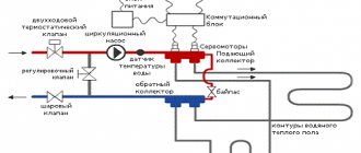
The node is an element in the form of a comb, from which leads extend for connecting heating devices. The number of pins may vary. If necessary, the element can be expanded with additional bends. Drain and air outlet valves, as well as heat meters, can be installed on the collector. The terminals can be equipped with adjustment or shut-off valves, which makes it possible to regulate or turn off the coolant flow. The device is installed in the heating system in the form of a collector block, which includes a return and supply comb, equipped with outlet valves and corresponding taps.
The collector heating system operates quite simply. The coolant, heated by the boiler to the required temperature, enters the supply comb. Here it is distributed between heating devices. A pipeline is laid to each of them, through which the coolant is directed. In the radiator, having given up some of its heat, the liquid is partially cooled, and through another pipe it enters the return comb and from there to the boiler. This distribution contributes to uniform heating of the radiators, since each of them has a separate supply pipe.
The coolant heated in the boiler goes to the supply manifold, where it is distributed through pipes suitable for each radiator. The cooled liquid is sent back to the boiler through the return manifold.
Note! The distribution comb of the heating system, installed on each floor of the heated building, allows you to obtain floor-by-floor individual heating circuits with autonomous control. If the need arises, you can turn off the heating of the entire floor or just a few devices, which greatly facilitates the maintenance and repair of the system
This will not affect the functioning of the entire structure at all. The use of a collector increases the operating efficiency of the equipment, since devices that regulate the temperature and pressure of the coolant, as well as flow meters, can be installed on its terminals.
Kinds
Manifold groups for heating systems are sold ready-made, and they can have different configurations and the number of outlets. You can select a suitable collector assembly and install it yourself or with the help of specialists.
However, most industrial models are universal and do not always fit the needs of a particular home. Redesigning or modifying them can significantly increase costs. Therefore, in most cases it is easier to assemble it from separate blocks with your own hands, taking into account the characteristics of a particular heating system.
Manifold group for heating system assembly
The design of the universal collector group is shown in the figure. It consists of two blocks for forward and reverse coolant flow, equipped with the required number of outlets. Flow meters are installed on the supply (direct) manifold, and thermal heads are located on the return manifold to regulate the return water temperature in each circuit. With their help, you can set the required coolant flow rate, which will determine the temperature in the heating radiators.
The manifold distribution unit is equipped with a pressure gauge, circulation pump and air valves . The supply and return manifolds are combined into one unit with brackets, which also serve to attach the unit to a wall or cabinet. The price of such a block is from 15 to 20 thousand rubles , and if some of the bends are not used, installing it will be clearly impractical.
The rules for installing the finished block are shown in the video.
Comb - collector unit
The most expensive elements in a manifold distribution block are flow meters and thermal heads . To avoid overpaying for unnecessary elements, you can buy a collector unit, the so-called “comb”, and install the necessary control devices with your own hands only where necessary.
The comb consists of brass tubes with a diameter of 1 or ¾ inches with a certain number of taps with a diameter of ½ inch for heating pipes. They are also connected to each other by a bracket. The outlets on the return manifold are equipped with plugs that allow you to install thermal heads on all or part of the circuits.
Some models may be equipped with taps, with their help you can regulate the flow manually. Such combs have a cast body and are equipped with a fitting/nut thread at the ends, which allows you to quickly and easily assemble a manifold from the required number of branches.
In order to save money, the manifold for heating systems can be assembled from individual elements independently or completely made by hand.
Classification
Since the design of the dispensing unit is not too complicated, it will not be possible to identify any fundamentally different types of it. Although manufacturers propose to classify hydraulic valves according to their intended purpose: for installation in a boiler room, for heated floors or for connecting heating radiators. In fact, the principle of operation of the collector does not change, and the difference can only lie in the number of “teeth” of the comb (2-12), as well as the features of the material of its manufacture:
1. Steel is a common option that can withstand pressure up to 10 atm. It is distinguished by an affordable price and an abundance of fakes on the market, especially among stainless steel.
2. Copper - calmly holds up to 30 atm with crazy heating of +600 °C, but not every heating system can “make friends” with it. If there are aluminum elements in the circuit, such a collector will have to be abandoned.
3. Polymers are the cheapest and weakest type of comb, which is made from polypropylene. They work in a harness with a pressure not exceeding 6 atm and are suitable only for heated floors.
4. Brass is an expensive and reliable metal for heating equipment. It is not afraid of corrosion and can withstand pressure up to 14 atm.
Additional auxiliary devices somewhat expand the range of combs, increasing their functionality. These can be control elements, shut-off valves, mixers, built-in sensors and automatic control systems. The more complex the heating distribution manifold, the higher its price. On the other hand, all this equipment, one way or another, will have to be purchased separately, and it is better if it is already supplied as a kit - adjusted to size and not requiring independent installation.
Pipe selection
Before starting work directly related to the creation of a heat supply system, it is necessary to coordinate the main parameters of the pipelines. First of all, the source of thermal energy, the inlets and outlets to the collector, as well as the pipeline must be of the same diameter. Otherwise, when using pipes of different diameters, adapters are used. Their installation requires additional material costs and time for installation.
The supply and return pipes through which the coolant liquid moves are made from different materials, but experts recommend using polypropylene pipes (for more details: “Do-it-yourself installation of a heating system from polypropylene pipes”).
Their advantage lies in their availability, practicality and ease of use during installation work. The selection of polypropylene pipes should be carried out on the basis of hydraulic calculations.
Failure to comply with the required diameters for pipes leads to such negative consequences as:
- violation of coolant circulation;
- airing of the heating circuit;
- uneven heating.
Purpose of the heating manifold
In any heating system, one important rule must be observed - the diameter of the pipe leaving the boiler must match or be slightly less than the total diameter of all circuits connected to this boiler. Failure to comply with this rule consistently leads to uneven distribution of coolant
For example, we can consider a system to which three separate circuits are connected:
- Radiator heating;
- Warm floor;
- Indirect heating boiler providing hot water supply.
The diameters of the nozzles at the outlet of the boiler and at the inlet of each of these consumers may be the same, but the total value of the latter will be an order of magnitude greater. As a result, a very simple phenomenon arises - the boiler, even if it operates at full capacity, is simply not able to simultaneously ensure the operation of all circuits connected to it. Because of this, the temperature in the house decreases.
Of course, you can try to use all circuits in turn so that they do not load the boiler at the same time. In theory, such measures seem possible, but in practice they turn out to be nothing more than half measures - after all, constant “juggling” with contours cannot be called an attribute of comfortable living in the house.
To get rid of such problems, you need to install a distribution manifold in the system. Typically, stainless steel pipes are used to make such collectors, but other options can be used - for example, polypropylene heating collectors are often found.
The design itself is a device with a set of pipes for the inlet and outlet of the coolant, as well as its separation into separate circuits. All operating parameters are adjusted using shut-off valves, which are included with any manifold.
The main function of the distribution manifold is reflected in its name - it distributes the coolant into separate circuits, and the intensity of its supply can be adjusted at each branch pipe. The result is several circuits that are completely independent from each other, each of which operates in its own temperature regime.
Of course, there is always the opportunity to simplify your work and purchase a ready-made collector, but this solution has disadvantages.
Thus, the production of heating collectors at a factory simply cannot take into account the characteristics of each heating system, so you will have to compensate for the characteristics of the collector with additional elements - and this is extra costs. Homemade devices may not be as versatile as factory ones, but they are much better suited for arranging individual projects.
Poliservis - Moscow: Engineering communications and pipelines
Why do they trust us?
| 1. We sell proven products. We are the official representative of PG Gidruss. This is a domestic manufacturer with a good reputation in Russia and neighboring countries. 2. We proceed from your capabilities. Each buyer has his own needs, we understand this and offer options to suit your pocket. Thrifty – budget options made of carbon steel. And for those who don’t want to save money, hydraulic arrows and stainless steel manifolds are available. 3. We complete. At your request, we select flow meters and other products for installation of piping. 4. We cooperate with companies and individual buyers. Both legal entities and individuals contact us. We select products according to each person's needs. 5. We accept orders for the production of non-standard models. When there is no suitable model in the catalog, we consider the option of piece production. |
What is a hydraulic arrow and why is it needed?
A hydraulic arrow is a metal or plastic product that is hollow inside. The shape resembles an elongated rectangle or a small “bottle” with welded pipes. They are equipped with threads, and together they form an input-output to which the consumer is connected
It is impossible to do without a hydraulic arrow in the boiler room of a private house or cottage for several owners. Therefore, if your heating system has more than two consumers (radiators, heated floors, sinks, etc.), purchasing a hydraulic separator or, more simply put, a hydraulic arrow cannot be avoided.
Installing this device will solve the following problems
- Balance of temperature and pressure in circuits.
- Protection of the heating boiler from water hammer associated with sudden temperature changes
- Uniform separation and mixing of working fluid
- Removing sludge and air from system pipelines
Paired with a hydraulic arrow, the boiler operates more smoothly. Such an insurer is indispensable for expensive models. For comparison: the price of a hydraulic needle starts from 4 thousand rubles, while repairs or a new boiler will cost several tens of thousands of rubles, or even more.
Don't forget about the manifold behind the hydraulic arrow!
Our catalog has several sections with heating manifolds. Formally, the collector is a comb with outputs to which consumers are connected. In our case, the manifold comes with a hydraulic arrow, the result is a balancing manifold. In terms of efficiency, this design is many times better than a hydraulic gun.
One product combines a whole list of useful functions
- Thread separation
- Temperature equilibrium on different branches
- Water hammer warning
- Possibility of installation of complex heating systems controlled by automation.
- Installing the collector will make repairs easier. If a problem occurs with one of the consumers, it is enough to turn off only it, and not the entire water supply.
BUYING FROM US IS NOT ONLY PROFITABLE, BUT ALSO PLEASANT!
In our catalog you will find more than two hundred product items, including those that customers asked us to add. We constantly monitor the market to offer you reasonable prices and quality products.
Still have questions? Send your request to The email address is being protected from spambots. Javascript must be enabled in your browser to view the address. or The email address is being protected from spambots. Javascript must be enabled in your browser to view the address.
Call +7
Working hours
10:00-20:00
Our details:
IP Konyukova A.P.
INN/OGRN 744715936671/315744800001380
454138, Chelyabinsk region, Chelyabinsk, Krasnogo Ural str., building 25, GSK "Krasnouralets", vld. No. 10
We will help you rationally distribute heat in your home!
Functional purpose
Let's start with the fact that there is one very important rule, and if it is not strictly adhered to, the heating system at home will not work well. This rule states that the diameter of the outlet pipe of a heating boiler should always be equal to or slightly less than the total diameter of all circuits consuming coolant
The best option is if it is larger.
For comparison, here is an example of a wall-mounted unit in which the diameter of the outlet pipe is ¾ inch. Imagine that this boiler will heat three separate circuits:
- The main heating is a radiator system.
- Warm floor.
- An indirect heating boiler that will use water intended for household needs.
Now imagine that each loop is at least ¾ inch in diameter, just like the boiler. But the total figure will be three times greater. That is, no matter how much you want, it will be simply impossible to dispense the required amount of coolant through the diameter of the heating boiler pipe so that it is enough for all three circuits. So much for the reduction in heat transfer throughout the entire area of the house.
Of course, individually all circuits will work fine. For example, the main circuit (radiator) without turning on underfloor heating will completely overpower the heated space. But as soon as you turn on the underfloor heating system, there won’t be enough coolant either here or there. The coolant has enough temperature, but its volume is not enough.
This rather serious problem is solved by installing a distribution manifold in the heating system. In essence, this is a structure made of stainless metal pipes, in the structure of which devices are installed for the input and output of coolant distributed along the circuits. To regulate temperature, pressure, flow volume and its speed, shut-off valves are installed along the terminals, which perform all the necessary functions.
The most important thing is that with the help of a distribution manifold you can control the temperature in a separate room. And this will not affect the neighboring rooms or the temperature of the house as a whole.
Collector device
The collector consists of two pipes:
- Connects the supply pipeline from the boiler to the supply circuits of heating systems. This compartment helps distribute hot water. Its device is especially helpful when the question arises of repairing a particular outlet. In this case, on a certain circuit where repair work needs to be carried out, the shut-off valve is closed. It simply shuts off the coolant supply.
- The return compartment regulates the pressure inside each circuit, which ensures the quality of coolant movement. And, therefore, the quality of heat transfer from heating systems.
Anyone who does not understand the essence of installing a distribution manifold begins to build various additional installations into the heating system: a circulation pump, valves for various purposes, and so on. Let's face it, this will not help; they cannot be used to increase the volume of coolant. You will simply make unnecessary expenses that will be in vain.
Attention! If you own a large multi-storey building, it is recommended to install a separate distribution manifold on each floor
Why do you need a distributor at all?
In a house where several heating circuits are installed, a distribution manifold is simply necessary. If you sum up the inlet diameter of each circuit and compare it with the diameter of the boiler connection pipe, it will become obvious that the latter indicator is much smaller. For example, the pipe on a wall-mounted gas boiler most often has a diameter of ¾ inches. Let's say we connect to it:
- radiator system;
- underfloor heating system;
- indirect heating boiler.
The connection diameter of each consumer is 1 inch. Will the coolant have time to flow through the ¾-inch outlet into three 1-inch inlets? The answer is obvious: during the operation of such a system, a shortage of coolant quite naturally arises when all heating circuits are turned on simultaneously.
For example, the radiator system works normally, but when an additional floor heating system is turned on, a decrease in temperature is observed and the air in the rooms does not warm up. Simply put, hot water is not entering the system quickly enough.
The distribution manifold allows you to fully control the operation of the heating system of a private home and customize it to the specific needs and desires of the owner
To solve the problem, you will need to install a distribution manifold. This is a special metal comb on which a number of input/output devices are installed for each individual heating circuit. The collector allows you to regulate the volume of coolant entering the system, its temperature, pressure in the system, etc. Using this device, you can centrally control the heating process of each individual room, equipped with its own heating circuit.
Connect through the distribution manifold:
- underfloor heating systems;
- radiator systems;
- converters;
- panel heating systems, etc.
The distribution manifold has supply and return sections that are connected to each other. The supply manifold allows you to control the actual supply of hot coolant to each specific heating circuit. This is very convenient, because in the event of a breakdown, you do not need to turn off the entire system; you can only shut off a separate circuit and make the necessary repairs. The return section of the manifold is necessary to regulate the pressure in a certain area of the system so that the heating quality reaches a given level.
You should not try to correct the situation by installing additional circulation pumps or special valves. They will not help fill the heating system with a sufficient amount of coolant. But the distribution manifold copes with this task quite successfully. Please note that in a large house with two or more floors, it is recommended to use a separate distribution manifold for each floor.
Pay attention to the material, which discusses in detail the principle of operation of the collector heating system and its design:.
Types of collectors in the heating system.
The collector for heating systems can be of the following types:
- Distribution - it is a round or square pipe with bends. The bends have different thread diameters. The boiler is connected to outlets of larger diameter, and heating devices are connected to outlets of smaller diameter. One such collector is installed on the supply pipe, the second on the return pipe. Look at the photo:
- Balancing - combines two distribution manifolds and a hydraulic arrow (hydraulic separator). This is a product that is ready for installation into the system, to which all that remains is to connect all the other equipment. It all looks like this:
Now let's take a closer look at their internal structure.
Where is the best place to install the equipment?
The ideal option would be to select a location for installing the collector during the design of the heating system. If the building has several floors, each has space for a collector block. Most often, a niche is installed under it in the wall, located at a small height from the floor. It should be located in a room protected from excess humidity. This could be a storage room, corridor, etc.
The device can be mounted directly on the wall if it is installed in a utility room, or placed in a special manifold cabinet. The cabinet is a metal box with a door and stampings in the side walls for pipes. Special fastenings for the collector block may be provided inside the equipment. You can find an overhead or built-in cabinet option.
Properly installed water heating manifold wiring guarantees the reliability and efficiency of the system. The likelihood of leaks, due to the small number of connections and tees, is minimized. Hidden wiring is also possible without disturbing the aesthetics of the room. And besides, you will agree that it is very convenient to regulate the heating temperature of each radiator and the entire room as a whole. A reliable system will be a real boon for those who highly value their own comfort.
Components and rules for soldering polypropylene pipes
Types of fittings for polypropylene pipes
The connection of polymer pipes can be done in several ways - soldering, detachable or permanent fittings, gluing. To install water heating with your own hands from polypropylene, diffusion welding is best suited. The main connecting element in this case are fittings.
It is important that the quality of the purchased components is not inferior to the pipes. All fittings for polypropylene pipes for heating do not have reinforcement
This is compensated by a thicker wall. They differ in appearance and scope:
- Couplings. Designed to connect individual pipes into a single pipeline. They can be either the same diameter or transitional for joining pipelines with a spill section;
- Corners. Scope of application – production of corner sections of highways;
- Tees and crosses. Necessary for dividing the highway into several separate circuits. With their help, a heating collector is made from polypropylene;
- Compensators. Hot water provokes thermal expansion of pipelines. Therefore, before soldering polypropylene heating, compensation loops should be installed that prevent surface tension from appearing in the line.
Before starting the soldering process, it is recommended to calculate the quantity of all consumables: pipes, fittings and shut-off valves. To do this, a heat supply diagram is drawn up indicating the configuration of each unit.
When installing polypropylene heating, it is necessary to use a special type of shut-off valves designed for soldering.
Self-soldering of polypropylene pipes
Set of tools for soldering polypropylene pipes
In order to make heating from polypropylene, you should purchase a minimum set of tools. It includes a pipe soldering iron, special scissors and a trimmer. The latter is necessary for stripping the pipes from the reinforcing layer in the soldering area.
Before soldering polypropylene heating, you should cut the required pipe size. Special scissors with a base for the pipe are designed for this. They will ensure an even cut without distortion.
To install polypropylene heating yourself, you will need to perform the following steps:
- Degrease the soldering area on the pipes.
- Using a trimmer, remove the reinforcing layer from the heating zone.
- Turn on the soldering iron and set it to a certain temperature.
- After heating the mirror, install the pipe and coupling into the nozzles. Do not make axial rotations while heating polypropylene.
- After a certain period of time, connect the pipe and coupling to each other.
- Wait until it cools down completely.
The procedure for soldering polypropylene pipes
Using this technology, you can make a reliable heating system from polypropylene with your own hands. The advantage of this method is the possibility of soldering on already installed sections of the main line. In this way, you can quickly repair the heating of a private house with your own hands from polypropylene.
An important point during independent soldering of water heating made of polypropylene is the heating time of the workpieces. It depends on the pipe diameter and wall thickness. If the material is not melted sufficiently, the diffusion process will be low, which will eventually lead to delamination of the joint. If the pipe and coupling are overheated, some of the material will evaporate, and as a result, the external dimensions will greatly decrease. Therefore, to install polypropylene heating, you should adhere to the recommended heating time for the plastic, depending on its diameter and wall thickness.
Table for soldering polypropylene pipes
During self-installation of polypropylene with your own hands, good ventilation in the room is necessary. When plastic evaporates, its volatile components can enter the respiratory system.
For a small amount of work, you can purchase a non-professional soldering iron that costs up to 600 rubles. With its help, you can solder a polypropylene heating system for a small house or apartment.
Do it yourself
The distribution manifold for the heating system can be made independently from polypropylene or metal. The choice of material does not affect the functionality, so you should choose a material that is easier to install yourself.
To install a polypropylene collector assembly, you need a special device for welding polypropylene pipes; for metal ones, a welding inverter and skills to work with it.
Calculation and distribution of contours
- warm water floors in each individual room;
- heating of rooms in which the temperature differs from others to a greater or lesser extent;
- heating of each individual floor and wing of the house.
The geometric dimensions of the collector should provide ease and convenience of access to the shut-off and control equipment of each branch. On average, the distance between the layers is recommended to be kept within 10-15 cm, between the supply and return collectors - 20-30 cm.
Pipes for connecting heating radiators are usually made with a diameter of ½ inch, the collector itself is 1-1½ inches, matching them with the diameter of the boiler pipes. When connecting a gas or electric boiler, top and bottom connections of the supply and return pipes are allowed; for solid fuel boilers, only side connections are allowed.
Polypropylene knot
It is made from scraps and remnants of polypropylene pipes using fittings. The pipes are welded using a special apparatus. For the supply and return manifolds, a polypropylene pipe Ø32 mm and tees 32/32/16 mm are used, connecting them using a polypropylene welding machine. The mode is selected in advance using pipe scraps.
A 32/32/32 mm tee is installed at one end, to which a drain valve is connected from below, and an air valve from above. At the other end of the collector, an inlet valve is installed, to which the supply or return pipe leading to the boiler is connected.
Shut-off valves are connected to 16 mm taps on the supply manifold, and flow meters are connected to the return manifold. The resulting units are attached to the wall with brackets.
Assembly of brass fittings
In a similar way, you can assemble a manifold from ready-made brass fittings: tees, valves. They are collected using flax tow or liquid fixative according to a pre-prepared scheme. The advantages of such a collector are its small size and low price compared to a ready-made collector group. But assembly requires care and precision, otherwise leaks may occur during operation.
Video: do-it-yourself collector units made of polypropylene and brass
From a profile pipe with your own hands
The most complex design of the distribution manifold is welded , made from square and round pipes. Such collectors are used for heating large objects with many circuits and a hydraulic arrow - a flow distributor.
To manufacture the collector, a profile pipe of 80x80 or 100x100 mm is used, as well as round pipes of the calculated diameter. The technology and step-by-step instructions for making the collector are given below.
- It is necessary to prepare a sketch of the future heating system. To do this, you need to determine all connected circuits and pipe diameters, as well as additional equipment connected to them - flow meters, pressure gauges, circulation pumps.
- On a piece of graph paper or a checkered piece of paper, draw a scale drawing of the collector assembly, maintaining the distances necessary for ease of installation. It is recommended to make the distance between the nozzles 10-20 cm, between the collector units - 20-30 cm. On the drawing you need to indicate not only the distances, but also the diameters of the nozzles.
- Decide on the installation location of the collector group and auxiliary equipment: expansion tank, pump, boiler safety group, boiler. Check the overall dimensions and make sure that the manifold group can be installed without interfering with other equipment.
- The profile pipe is marked in accordance with the diagram.
- A cutting torch is used to make holes according to the markings.
- Nozzles are welded to them - small sections of round-diameter pipe with pre-cut threads. First, they are tacked by spot welding, and then they are welded along the contour and the seams are carefully protected.
- Mounting brackets are welded to the resulting block.
- The resulting collector group is cleaned of scale, dirt, and rust, after which it is primed and coated with heat-resistant metal paint. For ease of maintenance, it is better to paint the supply and return circuits in different colors, traditionally red and blue.
The process of manufacturing a distribution manifold from a profile pipe is shown in the video.
For complex systems with a large number of circuits for different purposes, it is recommended to install a hydraulic arrow that will distribute and equalize the forward and reverse coolant flows to a safe pressure and temperature.
Video: hydraulic arrow, purpose and principle of operation.
Homemade collector
It's important to follow the direction
The manufacture of a homemade distribution manifold must begin with planning. You need to determine for yourself some components of the heating network at home.
- The number of circuits where the coolant will be directed.
- Number of heating equipment. Don’t forget to decide on its power, water temperature, and so on. That is, you will need its technical characteristics.
- If in the future you plan to integrate additional heating elements into the heating system, for example, a heat pump or solar panels, then it is best to take them into account in advance.
- Number of additional equipment (pumps, valves, fittings, storage tanks, thermometers, pressure gauges, etc.).
Now the design of the device is determined, especially it is necessary to take into account how each circuit will fit and from which side (bottom, top, side)
We draw your attention to some connection nuances
- Gas or electric boilers are connected to the collector either from below or from above. If a circulation pump is installed in the heating system, the connection is made only from the end of the comb.
- Indirect heating boilers and solid fuel units cut into the collector only from the end.
- The supply circuits of heating systems are cut either from above or from below.
It’s good if you transfer a small drawing of the collector design onto paper. This will give a visual picture that will make it easier to manufacture the device. In addition, it can accurately indicate the dimensional characteristics that will have to be maintained during the manufacturing process. For example, the distance between the pipes of the supply and return circuits should be within 10-20 cm. There is no need to do more or less, it will simply be inconvenient in terms of maintenance. The distance between the two compartments (supply and return) should be in the same range.
Make the device compact and beautiful. We recommend that you mark all threaded connections in the drawing indicating the thread sizes; do not forget to label all the necessary contours. This will prevent you from making mistakes when connecting. Now from the sketch it becomes clear how much and what materials you will need to make a homemade distribution manifold.
Manufacturing process
Please note that the supply and return compartments can be made from round or square pipes. Many masters prefer the latter option
They claim that it is easier to work with.
So, here is the manufacturing sequence:
- For all the dimensions indicated on the sketch, it is necessary to prepare the appropriate materials. These are almost all pipes.
- They are connected according to the design of the drawing in accordance with the purpose of each.
- The connection is made using a welding machine.
- Welding areas must be cleaned with an iron brush and, if necessary, degreased.
- The finished device must be tested for leaks. Therefore, all the pipes will have to be sealed, leaving only one. Hot water is poured into it. If none of the joints are leaking, it means that the work was carried out at a high level.
- The collector must be painted and dried.
- It is possible to install and connect all pipe systems with the installation of shut-off valves.
A simpler option
Now to the question: isn’t it better to buy a ready-made option? There is one “BUT” here. The finished distribution manifold may not exactly fit your heating system; you will have to equalize the thermal performance in other ways. For example, installing an additional comb. And these are extra costs and an extra amount of installation work. And a homemade comb, in which you have taken into account all the design features of heating your home, will exactly fit it and will work efficiently and efficiently.
So it’s worth thinking about the question that was posed at the beginning of the article, how to make a distribution manifold with your own hands? Let's just say this is a simple process that will take you one day. But you simply must have the skills to work with a welding machine and other plumbing tools. Without this, it will be impossible to guarantee the quality of the device.
Metal collectors
Heating collectors are often made of metal. The basis is steel profiles with a thickness of about three millimeters. They are produced mainly by specialized factories, so it is almost impossible to fake them. The GOST mark indicates compliance with the state standard. Craftsmen hold structural and stainless steel in high esteem. The combs are strong, weighty and durable.
Before starting welding, draw the design of the future module
All dimensions are indicated on the sketch, and the reinforcement and other component piping are conventionally designated. The more details, the better. This gives a general idea of how to rationally organize your work. Much depends on the power of the boiler, the number and location of consumers.
| This is interesting . Electric and gas boilers are connected to the collector from above or below. But if the system assumes a circulation pump, then the boiler is removed only from the end, like an indirect heating boiler. It’s easier with contours; in any case, they are placed either at the top or bottom of the comb. |
According to the dimensions indicated in the drawing, profiles, pipes and threads are selected. The workpieces are connected using a welding machine.
The joints are additionally protected and degreased. The finished product must be checked for leaks. Hot water is poured into one pipe, the rest are plugged. If signs of leakage appear somewhere, additional treatment is carried out. The finished product is painted with waterproof enamel with varnish, powder paint or polished to a shine on a special machine.
pros
- Reliability. Steel combs withstand all external loads, including mechanical ones.
- Tightness. Welded seams hold their shape for as long as possible.
- Accuracy. Thanks to the rigid structure of the metal, the design looks more compact.
- Exploitation. Retains characteristics for at least 10 years.
- Functionality. Performs several tasks at once.
Minuses
- High price. Compared to polyethylene collectors, metal ones will cost several times more.
- Weight. The weight of the device starts from five kilograms.
- Lengthy installation. Assembly will require more costs, both physical and time.
- Strict consistency. To make a truly high-quality collector, you need to follow a certain algorithm, which is quite difficult for an untrained master.
We hope we helped you at least a little. The next time you are wondering which collector is better, just remember our review and take action.
Radial scheme and heated floor
The radial scheme allows you to combine a homemade heating collector and a “warm floor” system. But this design has a number of features.
Before you begin to create it, you need to familiarize yourself with them:
- the heating manifold must be installed on the condition that it is equipped with control valves and thermostatic valves on absolutely all circuits;
- When laying pipes for a “warm floor” heating system, electrothermal drives and thermostatic heads are certainly used. Thanks to these devices, “warm floors” will be able to quickly respond to changes in temperature and maintain the necessary microclimate in each room;
- The option for arranging a distribution system can be different - standard (made according to a standard scheme) and individual. The last method deserves special attention. In this case, the boiler operates in normal mode without significant temperature changes, and fuel is consumed economically.