Home / Heating
Back
Published: 05/13/2020
Reading time: 6 min
0
4680
Modern heat supply schemes have an extensive heating network, with several heating circuits. Despite the good thermal efficiency of such systems, serious hydraulic problems arise. Due to high resistances in the network, heating water is not always correctly distributed along the circuits, which causes an imbalance in the system.
The correct piping of the boiler with a hydraulic arrow can level the situation. This coolant distributor operates reliably in three piping schemes and can be installed in any position
- 1 What is a hydraulic arrow
- 2 Purpose of the hydraulic arrow 2.1 In which case you can’t do without it
- 2.2 Operating modes
- 5.1 How to choose a hydraulic gun
What is a hydraulic arrow
A hydraulic arrow (hydraulic or hydrodynamic separator, hydraulic separator) is a high-quality plumbing device that I install in the piping circuit of the boiler unit and the in-house system to distribute heating water flows across several heating circuits, including to an external boiler and heated towel rail.
Separator for multiple circuits
The shape of the design is made with a round or square cross-section and has 4 connecting threaded or flanged pipes: upper inlet, lower outlet, and the rest for distribution heating circuits (CD).
The dimensions of the hydraulic arrow are determined by the thermal power of the boiler and will depend on the number and estimated hourly volume of the coolant according to the CO. Standard equipment of the hydraulic arrow:
- pressure gauge, thermometer;
- temperature sensor;
- thermoregulatory valve;
- shut-off and control valves;
- line for feeding the network;
- drain line.
Improved modifications combine the functions of a flow distributor, temperature control of heating circuits and a separator for releasing air and removing suspended particles from the internal boiler.
To do this, porous deaeration plates are installed vertically at the top of the structure. The sludge collector and magnetic trap are located at the bottom of the housing.
Hydroarrow
What is a hydraulic arrow?
If pumping equipment of significant power is installed in a multi-circuit complex heating system, then even it will not be able to cope with the different conditions and parameters of the network operation. Such inconsistencies in the operation of different circuits will negatively affect the operation of the heating boiler and shorten the service life of expensive equipment.
Branched heating networks cannot work harmoniously due to the fact that each circuit has its own performance and pressure. But even if each circuit is equipped with its own circulation pump, taking into account the parameters of the main line, the problem of system fragmentation will only worsen. This will lead to unbalancing of the networks, because each heating circuit will have its own parameters.
To solve the problem, one common boiler must heat the required amount of coolant, but each circuit must receive the required amount of heated liquid from the collector. In this case, the functions of the hydraulic system separator are performed by the manifold. A hydraulic separator is needed to separate the boiler flow from the general circuit. Another name for a hydraulic separator is a hydraulic arrow or HS (hydraulic arrow).
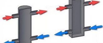
The name of the device comes from the analogy with a railway switch. Just as a railway switch directs trains in the required direction, a hydraulic switch distributes coolant flows across separate circuits. Externally, the device resembles a piece of round or rectangular pipe with end caps. The device is connected through a pipeline to the collector and boiler and has several pipes in the side.
How does a hydraulic separator work?
The boiler equipment pump accelerates the circulating coolant to a speed of 0.7-0.9 m/s, but the liquid passes through the hydraulic separator for heating at 0.1-0.3 m/s. A decrease in flow speed occurs due to a change in the direction of fluid flow and its volume passing through a certain section of the pipeline. But such a reduction in speed does not affect heat loss in the circuit.
Purpose of the hydraulic arrow
Hydroarrow is a component of the heat supply circuit that connects different KOs. The device ensures the minimum permissible pressure drop across the circuits, which makes it possible to safely shut down one or a number of circuits without a pressure surge in the remaining ones.
Therefore, the use of a hydraulic distributor in heating systems eliminates the impact of the pump in the boiler circuit on the performance of circulation pumps operating in the heat removal circuits and vice versa.
In what case can you not do without it?
The hydraulic arrow is effective for home heating schemes that have several independent heating circuits. Very often, especially when installing a European-assembled boiler, the manufacturer requires the mandatory installation of such a hydraulic separator in the wiring diagrams of heating sources.
Conditions for the mandatory installation of a floor-standing boiler water gun:
- for boiler units with thermal power above 50 kW that are under warranty;
- for branched circuits that require the creation of reliable hydraulic conditions and thermal balance;
- with a parallel connection of the hydraulic arrow with consumption circuits for minimal losses in pressure and heat energy;
- to ensure the calculated temperature difference between supply and return;
- to prevent water hammer in the heating network;
- if necessary, equalize the flow of heating water in the boiler and heating circuits;
- if it is necessary to balance the operation of several circulation pumps;
- if necessary, reduce the hydraulic resistance of the system.
Operating modes
There are three modes for piping the heating system with a hydraulic arrow. The first is when the electric circulation pump of the boiler unit pumps the entire volume of coolant in the internal heating circuit.
This option is very rare in reality. A modern automatic control system for heating systems works with thermostats that control the heating output of the boiler; it is practically impossible to ensure a constant flow of circulating water with such regulation.
The second option for the operation of the hydraulic arrow is installed when the water flow in one or more heating circuits is greater than the productivity of the electric boiler pump.
This can happen, for example, when the pumps are selected incorrectly. In this option, in order to ensure the required water flow in the circuit, return flow is supplied to it in addition to the heated coolant.
This option is undesirable for boiler operation, since it will greatly underestimate the water flow from the circuit, and the temperature difference between hot and cold water in front of the boiler will increase, which is not acceptable for all modifications of units.
The third piping mode is the most effective, designed for high productivity of the boiler pump, more than all boilers need.
In this situation, a portion of the supply coolant will be sent back to the boiler through the recirculation line, the water temperature will increase and, when the set temperature is reached, it will begin to operate in minimum mode. The system will achieve thermal balance, so the equipment will function with high efficiency.
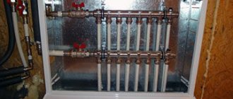
Heating comb, distribution manifold.
Heating distribution manifold
If we imagine this wiring in its simplest form, then:
This is a pipeline closed at one end and with several outgoing pipes connected to heating devices.
The number of outgoing pipes depends on the conditions of use and the number of radiators. Thanks to the comb, the fluid flow in the pipes is optimized. It also smoothes out pressure drops in the system. The manifold distributor is used in radial distribution due to the presence of separate coolant outlet and supply pipes for each battery. It is this device that ensures uniform heating of the radiators and the possibility of their separate adjustment. In addition to the above advantages, the collector allows you to include additional equipment into the overall system. designs. (for example: pool heating).
Heating distribution manifold
Summarizing the above, we can highlight the following positive aspects of the distribution manifold:
1. Thanks to the design features, uniform heating of the radiators is ensured. It is also possible to adjust the temperature in each individual room. 2. The entire heating network will be protected from water hammer, which will affect its service life. 3. Possibility of installing additional devices to increase its functionality.
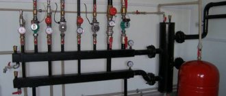
There are also two types of collectors based on their operating principle. There are combs for boiler rooms and local ones.
- In the first type, the supply part delivers liquid to individual parts of the heating system and is therefore equipped, in addition to taps, with circulation pumps. In addition, it has various sensors: pressure, temperature control and hydraulic arrow.
Heating distribution manifold with circulation pump
The hydraulic arrow serves to completely replace the cooled coolant with a hot one.
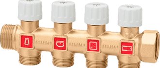
- The second type has smaller dimensions and the principle of its operation is as follows: unlike the first type, the coolant is diluted here. A special sensor is responsible for maintaining the constant temperature, which is triggered if it drops. It allows access to hot water from the boiler by opening a special valve. As a result, the cooled liquid mixes with the hot liquid and becomes the optimal temperature. Instead of a hydraulic needle, an additional circulation pump is used here. To achieve increased efficiency of the heating system in the same house, it is recommended to install both types of combs.
Installation location
For proper installation of hydraulic arrows, follow 5 general rules:
- For proper operation of the distributor, it does not matter in what position the hydraulic arrow is installed. The only important thing is the direction of the end pipelines, on which the operation of the automatic air vent and the sludge removal system depend.
- The distributor is installed after the boiler valve. The installation location is determined by the heating circuit; it is located as close as possible to the unit.
- If a collector circuit is used, the distributor is placed in front of the boiler unit.
- If it is necessary to connect an additional electric pump, the distributor is placed between it and the outlet pipe for the heating circuit.
- In order to properly connect the solid fuel unit, the hydraulic arrow is connected to the coolant outlet and inlet, then you can adjust the individual temperature for each circuit.
Calculation of hydraulic arrow
The hydraulic distributor is calculated using formula D to take into account the maximum mode according to the factory parameters of the boiler:
D = 3*d=1000* √ (4*Q)/(π *3600*ω)=18.8*√G/ ω,mm
Calculation of the diameter of the hydraulic valve taking into account the design thermal power of the boiler unit and the temperature difference between the forward and return lines:.
D = 3*d=1000* √ (4*P)/(π *C* ∆T*ω)=17.4*√G/(ω* ∆T), mm
Diameter of the hydraulic arrow pipe for incoming coolant:
d = √ (4*Q)/(π*V), mm
Where:
- D — D of the distributor body, mm;
- D — D of the inlet pipe, mm;
- P is the design heat output of the floor-standing boiler, kW;
- G is the highest coolant flow through the distributor, m3/hour;
- C—heat capacity of water, W/(kg*C);
- V is the speed of water through the CP, m/s;
- Q is the estimated hourly water consumption in KO, m3/h.
Buy or make it yourself
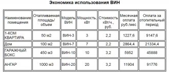
A ready-made set of European-assembled hydraulic guns with auxiliary equipment in the retail chain costs from 200 to 300 US dollars.
The user who purchases such a design will receive all the advantages of its operation in the heat supply system: fuel economy, reliable thermal and hydraulic conditions in the network and durability of the main boiler equipment.
Simple diagram of a hydraulic separator
Factory assembly solves not only distribution issues, but also protection of the system from water hammer, corrosion and sludge deposits in internal heating surfaces. All structural components are carefully calculated, manufactured using modern technology and adjusted in the factory.
Those home craftsmen who want to save money on distributors have plumbing experience and all the necessary equipment can be advised to make the hydraulic switch themselves, fortunately today there are quite detailed manufacturing methods and schemes on the Internet. The device belongs to complex hydraulic products and when performing them, the following must be taken into account:
- The drives must have a symmetrical, well-cut thread.
- The wall thickness of the pipes is chosen to be the same.
- The quality of welds must be high.
How to choose a hydraulic gun
The hydraulic arrow works effectively only if it is selected correctly. The basic characteristics when choosing a distributor are the thermal power of the boiler and the total hourly water consumption for all boilers. It should not exceed the hourly water flow through the boiler circuit.
Next, pay attention to the design features of the hydraulic arrow:
- cross-sectional shape - square or round
- number of pipes: 4, 6 or 8 inputs/outputs;
- water supply/discharge option;
- method of installation of pipes - on a common axis or with alternation.
Experts advise purchasing ready-made structures with pressure gauges, an air vent and a sump for cleaning the water circuit from sludge for wall-mounted boilers and hydraulic taps.
Correct piping of the boiler with a hydraulic arrow
The hydraulic needle, to which it is planned to connect more than 3 heating circuits, is usually manufactured together with manifolds - supply and return. The distributor is installed in such a way as to equalize the pressure between them.
Strapping scheme
The standard scheme for piping the boiler and connecting the hydraulic switch to the heating system is as follows:
- An electric circulation pump is mounted on the supply pipe, which should ensure uninterrupted movement of water in the hydraulic separator.
- After the circulation pump, a hydraulic arrow is mounted to form a small boiler circulation circuit for the floor-standing boiler.
- The section of the network between the hydraulic valve and the boiler on the return line is divided by inserting a check valve, which prevents recirculation of the coolant.
- For complex heat supply systems, additional supply and return collectors are installed.
Thus, the main task of the hydraulic switch is to create a reliable hydraulic regime in the heating circuits of the intra-house network. The basic elements of the piping with a hydraulic arrow are a boiler unit or a group of them and electric circulation pumps. Correct piping of the boiler with a hydraulic arrow will be carried out provided that the water flow in the boiler circuit is 10% greater than the total flow in all heating circuits of the house.
How to select parameters
The hydraulic separator is selected taking into account the maximum possible coolant flow rate. The fact is that at high speeds of liquid movement through the pipes, it begins to make noise. To avoid this effect, the maximum speed is assumed to be 0.2 m/s.
Parameters required for the hydraulic separator
By maximum coolant flow
To calculate the diameter of the hydraulic arrow using this method, the only thing you need to know is the maximum coolant flow that is possible in the system and the diameter of the pipes. With pipes everything is simple - you know which pipe you will use for wiring. We know the maximum flow that the boiler can provide (it is in the technical specifications), and the flow rate through the circuits depends on their size/volume and is determined when selecting circuit pumps. The flow rate for all circuits is added up and compared with the power of the boiler pump. A large value is substituted into the formula to calculate the volume of the hydraulic needle.
Formula for calculating the diameter of a hydraulic separator for a heating system depending on the maximum coolant flow
Let's give an example. Let the maximum flow rate in the system be 7.6 cubic meters/hour. The permissible maximum speed is taken as standard - 0.2 m/s, the diameter of the pipes is 6.3 cm (2.5 inch pipes). In this case we get: 18.9 * √ 7.6/0.2 = 18.9 * √38 = 18.9 * 6.16 = 116.424 mm. If we round, we find that the diameter of the hydraulic needle should be 116 mm.
According to the maximum boiler power
The second method is to select a hydraulic needle according to the boiler power. The estimate will be approximate, but it can be trusted. The boiler power and the difference in coolant temperatures in the supply and return pipelines will be needed.
Calculation of hydraulic arrow according to boiler power
The calculation is also simple. Let the maximum boiler power be 50 kW, the temperature delta be 10°C, the diameters of the pipes be the same - 6.3 cm. Substituting the numbers, we get - 18.9 * √ 50 / 0.2 * 10 = 18.9 * √ 25 = 18.9*5 = 94.5 mm. Rounding, we get the diameter of the hydraulic needle 95 mm.
How to find the length of the hydraulic arrow
We have decided on the diameter of the hydraulic separator for heating, but we also need to know the length. It is selected depending on the diameter of the connected pipes. There are two types of hydraulic arrows for heating - with taps located one opposite the other and with alternating pipes (located offset from one another).
Determining the length of the hydraulic arrow from a round pipe
It is easy to calculate the length in this case - in the first case it is 12d, in the second - 13d. For medium-sized systems, you can select the diameter depending on the pipes - 3*d. As you can see, nothing complicated. You can calculate it yourself.