The multi-zone chiller-fan coil climate system is designed to create comfortable conditions inside a large building. It works constantly - it supplies cold in the summer, and heat in the winter, warming the air to the set temperature. It’s worth getting to know her device, don’t you agree?
The article we propose describes in detail the design and components of the climate system. Methods for connecting equipment are given and discussed in detail. We will tell you how this thermoregulation system works and functions.
Components of the chiller-fan coil circuit
The role of the cooling device is assigned to the chiller - an external unit that produces and supplies cold through pipelines with water or ethylene glycol circulating through them. This is what distinguishes it from other split systems, where freon is pumped in as a coolant.
For the movement and transmission of freon, a refrigerant, expensive copper pipes are needed. Here, water pipes with thermal insulation cope well with this task. Its operation is not affected by the outside air temperature, while split systems with freon lose their functionality already at -10⁰. The internal heat exchange unit is a fan coil.
It receives liquid at a low temperature, then transfers the cold into the room air, and the heated liquid is returned back to the chiller. Fan coil units are installed in all rooms. Each of them works according to an individual program.
The main elements of the system are a pumping station, a chiller, a fan coil. The fan coil can be installed at a great distance from the chiller. It all depends on how much power the pump has. The number of fan coil units is proportional to the chiller power
Typically, such systems are used in hypermarkets, shopping malls, structures built underground, and hotels. Sometimes they are used as heating. Then heated water is supplied to the fan coils through the second circuit or the system is switched to the heating boiler.
Connecting the chiller and fan coil
The smooth functioning of the system occurs by connecting the chiller to one or more fan coil units through thermally insulated pipelines. In the absence of the latter, the efficiency of the system drops significantly.
Each fine coil has an individual piping unit, through which its performance is adjusted both in the case of heat and cold generation. The refrigerant flow in a separate unit is regulated by means of special valves - shut-off and control valves.
To direct chilled water to the heat exchanger, one pipe is connected to the fan coil unit, and the other is connected to the chiller to drain the liquid. The system design allows mixing of refrigerant with coolant
If mixing of coolant and refrigerant is not allowed. the water is heated in a separate heat exchanger and the circuit is supplemented with a circulation pump. To ensure smooth adjustment of the flow of working fluid through the heat exchanger, a 3-way valve is used when installing the piping circuit.
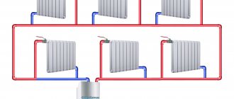
If a two-pipe system is installed in a building, then both cooling and heating occurs due to a cooler - a chiller. To increase heating efficiency using fan coil units during the cold season, in addition to the chiller, a boiler is included in the system.
Unlike a two-pipe system with one heat exchanger, the four-pipe system contains 2 of these units. In this case, the fan coil can operate for both heating and cold, using in the first case the liquid circulating in the heating system.
One of the heat exchangers is connected to a pipeline with refrigerant, and the second to a pipe with coolant. Each heat exchanger has an individual valve controlled by a special remote control. If such a scheme is used, the refrigerant is never mixed with the coolant.
Since the temperature of the coolant in the system during the heating season ranges from 70 to 95⁰ and for most fan coil units it exceeds the permissible level, it is first reduced. Therefore, hot water supplied from the central heating network to the fan coils passes through a special heating point.
Fan coil units
The fan coil unit consists of a radiator, which plays the role of a heat exchanger, and a fan. One has only to drive hot or cold water (or any suitable technical liquid) through the inside of the device, and it takes on the temperature of the radiator with the help of a fan supplying air to it.
But where can I get chilled water to supply it to the fan coil? By itself, this simple device is not able to pre-cool liquid. For this, a chiller is needed - a refrigeration unit that forms air conditioning systems with a chiller and fan coils.
Fan coil units are:
- cassette;
- channel;
- wall;
- floor-ceiling;
- cabinet floor;
- unframed.
One chiller is enough to supply cooled liquid to ten fancols. In addition, you can configure the operation of fan coils both in general mode and in autonomous mode for each.
Main classes of chillers
The conditional division of chillers into classes occurs depending on the type of refrigeration cycle. Based on this feature, all chillers can be conditionally classified into two classes - absorption and steam compressor.
The structure of the absorption unit
An absorption chiller or ABCM uses a binary solution with water and lithium bromide present in it - an absorber. The principle of operation is the absorption of heat by the refrigerant in the phase of converting steam into a liquid state.
Such units use the heat generated during the operation of industrial equipment. In this case, an absorbent absorber with a boiling point significantly higher than the corresponding parameter of the refrigerant dissolves the latter well.
The operating diagram of a chiller of this class is as follows:
- Heat from an external source is supplied to a generator, where it heats a mixture of lithium bromide and water. When the working mixture boils, the refrigerant (water) completely evaporates.
- The steam is transferred to the condenser and becomes a liquid.
- The refrigerant enters the throttle in liquid form. Here it cools and the pressure drops.
- The liquid enters the evaporator, where water evaporates and its vapors are absorbed by a lithium bromide solution - an absorber. The air in the room is cooled.
- The diluted absorbent is reheated in the generator and the cycle starts again.
Such an air conditioning system has not yet become widespread, but it is fully in tune with modern trends regarding energy saving, and therefore has good prospects.
Design of vapor compression units
Most refrigeration units operate on the basis of compression cooling. Cooling occurs due to continuous circulation, boiling at low temperatures, pressure and condensation of the coolant in a closed-type system.
The design of a chiller of this class includes:
- compressor;
- evaporator;
- capacitor;
- pipelines;
- flow regulator.
The refrigerant circulates in a closed system. This process is controlled by a compressor, in which a gaseous substance with a low temperature (-5⁰) and a pressure of 7 atm is compressed when the temperature is raised to 80⁰.
Dry saturated steam in a compressed state goes into the condenser, where it is cooled to 45⁰ at a constant pressure and converted into liquid.
The next point on the movement path is the throttle (reducing valve). At this stage, the pressure decreases from the value corresponding to condensation to the limit at which evaporation occurs. At the same time, the temperature drops to approximately 0⁰. The liquid partially evaporates and wet steam is formed.
The diagram shows a closed cycle according to which a vapor compression unit operates. In the compressor (1), wet saturated steam is compressed until it reaches pressure p1. In the compressor (2), the steam gives off heat and is transformed into liquid. In the throttle (3), both pressure (p3 - p4) and temperature (T1-T2) decrease. In the heat exchanger (4), pressure (p2) and temperature (T2) remain unchanged
Having entered the heat exchanger - evaporator, the working substance, a mixture of steam and liquid, gives off cold to the coolant and takes heat from the refrigerant, drying at the same time. The process occurs at constant pressure and temperature. Pumps supply low temperature liquid to the fan coil units. Having passed this path, the refrigerant returns to the compressor to repeat the entire vapor compression cycle again.
Specifics of a vapor compression chiller
In cold weather, the chiller can operate in natural cooling mode - this is called free cooling. At the same time, the coolant cools the street air. Theoretically, free cooling can be used at an external temperature of less than 7⁰C. In practice, the optimal temperature for this is 0⁰.
When configured in “heat pump” mode, the chiller operates for heating. The cycle undergoes changes, in particular, the condenser and evaporator exchange their functions. In this case, the coolant must be heated rather than cooled.
The simplest are monoblock chillers. They compactly combine all the elements into one. They go on sale 100% complete, right down to the refrigerant charge.
This mode is most often used in large offices, public buildings, warehouses. The chiller is a refrigeration unit that produces 3 times more cold than it consumes. Its efficiency as a heater is even higher - it consumes 4 times less electricity than it produces heat.
Mounting features
All installation features depend on the fan coil model you choose.
With housing, without housing. The cabinet can be installed anywhere, as long as it fits into the interior.
Without a housing (in the case of a pre-designed and prepared place for installation into a wall or installation under a suspended ceiling, an air conditioning system). The advantage is that all unwanted areas of the device are hidden, leaving only the functionally important part visible - the radiator grille.
Ventilation is directed to the required room; the fan coil fan does an excellent job of supplying it through the pipes.
One heat exchanger. A fan coil has only one radiator in which warm or cold liquid circulates, which ultimately leads to little functionality and inconvenience due to the possibility of use only in one season.
Two heat exchangers. It is more popular and practical, it has two water supply circuits, cold and hot. Each is connected to a separate source. This will allow you to easily change hot and cold air flows.
During installation, you must first connect the liquid supply circuits to the fan coil unit. Hot water is easily taken from the battery (the simplest solution but requires the installation of a pump and pressure reducer), but for cold water you will need a chiller.
By location: floor or wall. When installing fan coils in accordance with this paragraph, you must take into account the fact of further ease of access to the device for control and maintenance.
Air conditioning circuit
Two-pipe. Air is taken in through one pipe, and out from the other. This fan coil often has one heat exchanger
Three-pipe. Here everything is more practical, since two mains of cold and hot water supply are supplied.
Four-pipe. The system is equipped with two, three, and sometimes more circuits. The advantage is the ability to simultaneously heat and cool different rooms and halls at any time of the year.
Cassette types of fan coils
Single threaded. One stream of air.
Four-thread. The air is distributed in four directions. With the correct choice of Fan Coil strength according to the square footage of the room, starting such a system will quickly create the temperature you set in the room.
Six-thread. Although they have a high price, their popularity does not decrease. They do an excellent job with large volumes of work, in shopping malls and entertainment centers.
Duct
Equipment of this type is used in large production facilities and office centers. The fan coil is installed in a utility room and is hidden from the eyes of users; due to its location in another room, its operation remains silent and does not disturb workers. The device itself is connected to centralized ventilation, supplying air at the required temperature to the rooms. Thus, the entire business center has its own stable, comfortable microclimate
Maintenance of fan coil units, according to the recommendations of experts, should occur once every 3 months. Major inspection - once a year. Self-service 1-2 times a month, it consists of wiping with a damp cloth. This is necessary to protect the fan coil from fungi that can form on it due to temperature changes during working and non-working hours.
As a result, when both devices work in tandem, they are called a chiller-fan coil system. Their action has one goal - creating favorable temperature conditions and increased comfort. This is more versatile than freon designs. Installation of any number of fan coil units, where there are restrictions on the length of freon pipes.
What is the difference between refrigerant and coolant?
A refrigerant is a working substance that, during the refrigeration cycle, can exist in different states of aggregation at different pressure values. The coolant does not change phase states. Its function is to transfer cold or heat over a certain distance.
The transport of refrigerant is controlled by a compressor, and the coolant is transported by a pump. The temperature of the refrigerant can fall below the boiling point or rise beyond it. The coolant, unlike the refrigerant, constantly operates at temperatures that do not rise above the boiling point at the current pressure.
The role of the fan coil in the air conditioning system
Fan coil is an important element of a centralized air conditioning system. The second name is fan coil. If the term fan-coil is translated from English literally, it sounds like a fan-heat exchanger, which most accurately conveys the principle of its operation.
The design of the fan coil unit includes a network module that provides connection to the central control device. The durable case hides the structural elements and protects them from damage. A panel is installed outside, evenly distributing air flows in different directions.
The purpose of the device is to receive low-temperature media. The list of its functions also includes both recirculation and cooling of air in the room where it is installed, without the intake of air from outside. The main elements of the fan-coil are located in its body.
These include:
- centrifugal or diametrical fan;
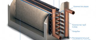
- heat exchanger in the form of a coil, consisting of a copper tube and aluminum fins mounted on it;
- dust filter;
- Control block.
In addition to the main components and parts, the design of the fan coil unit includes a tray for collecting condensate, a pump for pumping out the latter, an electric motor, through which the air dampers are rotated.
The photo shows a Trane duct fan coil. The productivity of double-row heat exchangers is 1.5 – 4.9 kW. The unit is equipped with a low-noise fan and a compact housing. It fits perfectly behind false panels or behind a suspended ceiling structure
Depending on the installation method, there are ceiling fan coils, duct units, mounted in ducts through which air flows, unframed units, where all elements are mounted on a frame, wall-mounted or console units.
Ceiling devices are the most popular and have 2 versions: cassette and duct. The first ones are installed in large rooms with suspended ceilings. The housing is located behind the suspended structure. The bottom panel remains visible. They can disperse air flow on two or all four sides.
If the system is planned to be used exclusively for cooling, then the best place for it is the ceiling. If the structure is intended for heating, the device is placed on the wall in its lower part
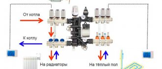
The need for cooling does not always exist, therefore, as can be seen in the diagram depicting the operating principle of the chiller-fincoil system, a container is built into the hydraulic module that acts as an accumulator for the refrigerant. The thermal expansion of water is compensated by an expansion tank connected to the supply pipeline.
They control fan coils in both manual and automatic modes. If the fan coil operates for heating, then the cold water supply is manually cut off. When it is working for cooling, the hot water is shut off and the path is opened for the flow of cooling working fluid.
Remote control for controlling both 2-pipe and 4-pipe fan coil units. The module is connected directly to the device and placed near it. The control panel and wires for its power are connected from it.
To operate in automatic mode, the panel sets the temperature required for a specific room. The set parameter is maintained by means of thermostats that adjust the circulation of coolants - cold and hot.
The advantage of a fan coil unit is expressed not only in the use of a safe and cheap coolant, but also in the quick elimination of problems in the form of water leaks. This makes their service cheaper. The use of these devices is the most energy-efficient way to create a favorable microclimate in a building
Since any large building has zones with different temperature requirements, each of them must be served by a separate fan coil unit or a group of them with identical settings.
The number of units is determined at the system design stage by calculation. The cost of individual components of the chiller-fan coil system is quite high, therefore both the calculation and design of the system must be performed as accurately as possible.
Operating principle
The device operates on the principle of the heater mentioned above: antifreeze or water of a certain temperature flows through the coil tubes, and a fan blows room air through the fins. Heat exchange occurs, the flow is heated or cooled. Hence the second name of the device – fan coil.
Features of the fan coil:
- the unit is capable of operating in heating or cooling mode depending on the temperature of the incoming water;
- the main function is to transfer heat or cold produced by other installations to the air;
- the fluid flow is provided by an external pump, there is no own pump;
- the intake air flow is cleaned from dust by a filter;
- usually the fan coil unit processes internal room air (full recirculation);
- some models integrated into the forced ventilation system can heat/cool the supply air;
- The heating/cooling power is regulated in two ways - by changing the fan performance and limiting the water flow with a two-way solenoid valve.
Note. The power is regulated by the electronic unit of the device - it opens/closes the valve and changes the speed of the impeller according to the signal from the temperature sensor or room thermostat.
So, a fan coil is a component of a centralized climate system that maintains the air temperature in a specific room or in a certain area of the production workshop. Additional functions:
- drainage;
- ventilation (ventilation mode);
- mixing fresh air is an option;
- remote control control;
- heating the flow with an electric heating element (also an option).
The difference between a fan coil unit and a split system lies in the principle of operation - it does not have a vapor compression cycle, the working fluid is water, which does not change the state of aggregation. Moreover, thermal energy comes to the radiator from the outside along with the liquid, as provided in heaters.
Sources of cold/heat can be:
- Traditional boilers using various energy sources. It is clear that this equipment only provides heating of water or antifreeze.
- There are two types of heat pumps (HP) – geothermal and water. In winter, the installation heats the coolant; in summer, on the contrary, it cools it.
- Chillers are powerful refrigeration machines with air or water cooling of the condenser.
Reference. Modern chillers operate in winter-summer mode and are equipped with inverters - frequency regulators of compressor speed. Thanks to this, the refrigeration unit can heat the coolant (like a heat pump) at minus 15...20 °C outside, although the performance is noticeably reduced.
The most common combination is a chiller-fan coil system. This is the best option for the price of the equipment; it will be more expensive to buy and install a VT of similar performance. Read below to see how the circuit units interact.
There is a valve inside the unit to vent air after installation and filling the pipeline network with coolant


