Electronic temperature regulator.
Electronic temperature regulator
The most complex type of thermostat in its design. The main element of this device is a microprocessor, through which the required temperature in the room is set.
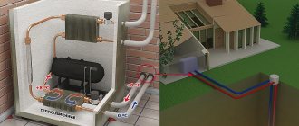
There are modifications of electronic devices adapted for boilers and pumps. The design of this thermostat is similar to a mechanical one: the thermostatic part of the device (bellows) is made in the form of a cylinder with corrugated walls and filled with a special substance that reacts to changes in ambient temperature.
The operating principle consists of the following steps:
- As the ambient temperature increases, the substance in the bellows begins to expand.
- The expansion of the substance contributes to the formation of pressure on the cylinder walls, as a result of which the rod is set in motion and closes the valve responsible for the flow of coolant.
- When the temperature drops, the opposite situation occurs when the valve opens and releases the coolant.
The most movable part of the electronic thermostat is the bellows, which has a huge safety margin. It can work for decades and shrink hundreds of thousands of times.
Electronic devices are divided into two categories:
- Closed type regulators do not have the ability to automatically detect ambient temperature. They are adjusted manually to the required temperature in the room.
- An open type regulator can be programmed for a specific action algorithm. For example, when the ambient temperature increases by a certain number of degrees, the operating mode of the device changes. In addition, the device has a timer that can be set to start the desired mode. These thermostats are mainly used in large industries. Electronic devices require either batteries or a rechargeable battery to operate.
Thermostats
The thermostat for water heating consists of two elements - a valve (valve) and a thermoelement. The valve serves to regulate heat transfer; it changes the water flow depending on the air temperature. The valve consists of a body and a spool.
Thermostat design
The valve capacity is determined by the height of movement of the spool. So, in this case, valves are low-lift and full-lift. In low-lift ones, the lifting height of the spool is equal to 0.05 of the seat diameter. Typically, such valves are used in systems where the liquid medium does not require large throughput. Full lift ones have a spool height higher than 0.25 times the size of the seat diameter. Used in systems with gaseous media.
Tip: Along with spring valves, lever-weight valves are also used. A lever-load mechanism is a shut-off control valve for heating, where the spool is connected to a lever where a load is hung. The weight can be moved along the entire length of the lever, adjusting the force with which the spool is pressed against the seat.
When the pressure of the medium on the lower plane of the spool is greater than the pressure force of the lever, the valve opens and water from the pipes flows through the discharge pipe.
For more information about adjustment equipment, watch the video:
Water temperature regulator in the heating system.
Regardless of which thermostat is used: mechanical, electronic or semi-electronic, two types of substances can be used as the thermostatic part - in the form of gas or liquid.
Based on this, regulators are gas-filled or liquid-filled:
- Gas appliances have a long service life, more than 20 years. Compared to a liquid element, a gas element responds more accurately and smoothly to changes in ambient temperature.
- Liquid devices are characterized by greater accuracy during the transfer of internal pressure to the rod.
Both types of thermostats come either with a built-in sensor or with a remote one.
The temperature regulator on the heating radiator, which has a built-in sensor, must be installed in a horizontal position to prevent the effect of heat from the pipes.
A device with a remote sensor is best used in the following cases:
- The radiator is covered with curtains made of thick fabric
- The thermostat is located vertically
- The depth of the battery is more than 160 mm.
- The distance from the thermostat to the window sill is less than 10 cm or more than 22 cm.
- The battery is located in a wall niche.
In these cases, the built-in sensor may not function correctly, unlike the remote one. In most cases, the sensors are installed at right angles to the battery (90 degrees). Otherwise, the heat from the radiator will negatively affect the readings of the device.
Direct acting temperature controller.
These types of devices, unlike indirect ones, are represented by mechanical thermostats. They do not require additional sources of energy to function.
Direct acting temperature controller
This condition is especially important when used in large industries and in the housing and communal services sector. The design includes a special shut-off valve with a variable flow area. A thermostatic element is responsible for its control.
The operating principle is simple: when the ambient temperature increases or decreases, the gas/liquid expands or contracts, creating an increase or decrease in pressure, which in turn affects the regulation mechanism.
Danfoss, temperature controller for the battery.
Danfoss temperature controller for battery
One of the largest manufacturers of thermostats for heating systems is the Danish company Danfoss. Their products are presented in almost all major cities of our country. Most products use a gas-filled bellows.
Danfoss temperature controller
A special feature of these regulators is that the thermostatic valve is connected directly to the battery, and the thermostat itself is mounted on it. The operating principle of Danfoss products is the same as in other regulators. Depending on the increase or decrease in ambient temperature, gas expansion or condensation occurs. Pressure fluctuations in the bellows affect the spool rod, which leads to an increase or narrowing of the clearance in the valve.
There are the following designations for Danfoss thermostats:
- RTS, bellows filled with a substance in a liquid state.
- RTD-G, filled with gaseous substance. Used for one-pipe or two-pipe systems
- RTD-N is also filled with a gaseous substance. Used for heating systems equipped with circulation pumps.
In addition, the company's products can be made with many additional functions and the kit always includes parts to simplify installation and operation.
Installation of the device is carried out according to general principles:
- Initially, markings are applied according to which it will be necessary to cut the pipe. It is worth remembering the size of the valve itself.
- Turning off the heating system and draining all the coolant from it.
- The thread is applied under the valve.
- A special sealing compound is applied to the junction of the pipe and the valve.
- Screw the valve onto the thread and tighten.
- Remove the fuse and put on the valve body.
- Final check of connections and switching on of the heating system.
Classification of thermostats
There is no generally accepted classification, so we will try to divide thermostats for hot water supply systems conditionally.
Based on the operating principle of control systems
- Pneumo- or hydromechanical, direct action. These are the simplest regulators. They use bellows filled with liquid and gas that change their volume depending on temperature. At the same time, the bellows is lengthened or shortened and activates the actuator. This is how regulators on radiators work.
An outdated system, but due to the ease of insertion, it is still used today. Another advantage of such regulators is their independence from power supply, which they simply do not need. Most often they also do not have a control unit.
- Pneumohydromechanical with indirect command pipelines. They also most often use bellows sensors. But pulse pipelines and network water pressure are used to transmit and amplify the signal from them. Unlike the previous version, they can work on more powerful hot water systems with high pressure pipelines.
- Electromechanical. In them, the actuators are already electrically driven (motor or solenoid) and there is a control side. To connect them with the sensor, intermediate relays can be installed.
- Electronic. The most common variety today. In them, the operation of the system is controlled by an electronic circuit. It can be analog (almost never found) or digital. Modern thermostats for hot water supply usually include microcontrollers in their electronic circuit and, thanks to software control, they are very easy to reconfigure.
According to the installation diagram of thermostats
The installation diagrams of the regulators are determined by the insertions of sensors and actuators. The control unit, if there is one, as is understandable, is mounted in any convenient place.
At the location where the sensor is inserted
There are several options:
- Insertion at the outlet of hot water from the heat exchanger. This is the most common method; it is prescribed in almost all operating manuals for thermostats. Moreover, the second method described below is impossible with a DHW system without recirculation, since there is no return there. The disadvantage is that you need to take into account the cooling on the way to the consumer and slightly increase the temperature setting.
- Insertion on the return of hot water pipelines. The method is rarely used, but only it can ensure compliance with the set temperature at all points of water collection.
- Connection to the network water supply. It is used when installing the simplest regulators, in which the actuator is located in the same housing with the sensor. Supply tapping is usually used when the coolant and hot water in the boiler move in countercurrent and the outlet temperature of the latter is almost equal to the supply temperature.
- Insertion on the return of the network water. It is used if water and coolant in the boiler move in the same direction, in this case the hot water at the outlet will be heated to the return temperature.
At the places where the actuators are inserted
There are four installation schemes for thermostat actuators:
- A two-way (faucet, valve, valve, etc.) actuator is mounted on the network water pipelines pumped to the boiler. The actuator blocks the return or supply cross-section. This is the simplest insertion scheme and the most commonly used one.
- A two-way actuator is installed on the mains water bypass in front of the boiler and, when opened, by bypassing part of the flow, it reduces the flow through the heat exchanger. This is how they crash least often.
- A three-way valve or similar valve with a drive is inserted. It simultaneously bypasses part of the flow through the bypass and presses the supply to the heat exchanger. The most profitable option, as it provides effective regulation and minimally affects the modes of other nodes of the heating network.
- Two two-way shut-off devices are installed on the coolant supply or return and bypass. The system works in exactly the same way as with a three-way valve (being its imitation). Requires a more complex control scheme. The scheme is rarely used.
Additionally, you can watch the video in this article, which talks about such systems. Next, we will analyze several industrially produced and currently used thermostats, as well as one device for self-assembly.
Mechanical temperature controller.
Mechanical temperature controller
The simplest type of device. It is distinguished by its low price, easy use and fairly clear operation
The volume of coolant entering the battery is adjusted manually. The main disadvantage of the device is the lack of markings on the adjustment body. The required temperature will have to be determined “by eye”.
A mechanical temperature controller consists of the following parts: a regulating element, a drive and a special container (bellows), inside which the regulating substance is located in a gaseous or liquid state.
Operating principle of a mechanical thermostat
The principle of operation is as follows: when the position of the lever changes, gas or liquid rushes into the spool and acts on the moving element - the rod. When the rod moves, the clearance for coolant movement narrows or expands. This regulates the temperature.
Before setting up the device, you should close the doors and windows in the room with the regulator, and set the device to the maximum temperature. Heat transfer will be maximum. Then turn the regulator to the minimum value. At the moment when the thermometer shows the desired temperature, open the valve until we hear the flow of water. We fix the position of the head.
Coolant flow regulator
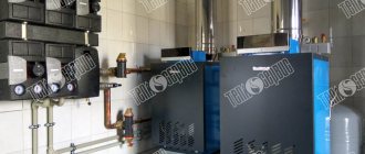
The coolant flow regulator is used to supply hot water of specified parameters to the heating network of buildings; it is installed in buildings between the heating network and the heat consumer. The essence of the invention is that an actuator in the form of an electromagnetic valve, controlled by an electronic regulator, supplies hot water in pulses. Used in public utilities. 1 n.p.f., 1 ill.
The utility model relates to devices that provide heat supply to buildings and are installed in individual heating points between the heating network and the heat energy consumer. Coolant flow regulators are used in public utilities.
Heating of buildings is carried out from central boiler houses with hot water, which is supplied through the heating network to individual heating points. Coolant flow regulators are the connecting link between the heating network and heat consumers. Coolant flow regulators ensure the supply of hot water to buildings at a certain temperature and pressure, as well as the required amount of hot water for domestic needs, which creates a given temperature regime in the building.
The required amount of water for heating a building in an individual heating point is determined by a coolant flow regulator, which, based on a signal from temperature sensors, increases the supply of hot water when the temperature in the building is below normal or reduces the supply of hot water when the temperature in the building is above normal. For this purpose, a system for regulating the water supply to the building is created, which consists of pipelines through which hot water is transported into the building, and cold water is removed back into the heating network for heating, flow regulator, auxiliary valves, mixing devices for water circulation in the building, filters, regulator pressure drop, heat measurement and metering devices.
There is a known coolant flow regulator used in an individual heating point, taken as an analogue [1].
An individual heating point consists of pipelines supplying hot water and discharging cold water. A filter, a differential pressure regulator, a control valve with an electric drive controlled by an electronic regulator, a circulation pump are installed on the supply pipeline, and a check valve is installed between the supply and discharge pipelines.
The operation of an individual heating point occurs as follows. Hot water flows through the supply pipeline through the filter into the differential pressure regulator, which maintains a constant differential pressure at the inlet of the heating station. A control valve is installed in series with it, which allows as much hot water to flow as is necessary to create the desired temperature in the building. Next, through a circulation pump, water is supplied to the building’s heat exchangers. From the heat exchangers, cooled water enters the heating network for reheating. The control valve is controlled by an electronic controller, which adjusts the amount of hot water supplied to the heat exchangers depending on the outside air temperature, water temperature and air temperature in the building.
Regulation in such a heating system occurs in a proportional mode, that is, when the heating radiators and rooms are cooled more, hot water constantly flows more all the time. The speed of the water depends on the temperature of the hot water and the air temperature outside the room. When the water speed is insignificant, hot water will be in the first batteries along the flow, and cold in the rest. To mix water in the heating system, a circulation pump is used, which transports water through a closed ring of the building's heating system.
The disadvantage of this system is the low reliability of the design due to the presence of an electric pump, which can stop when it turns off
power supply In addition, the presence of a pump increases the cost of completing a heating point and the cost of operating the heating point.
A coolant flow regulator is known, used in an individual heating point, taken as a prototype, the installation diagram of which in a heating point is shown in [2].
An individual heating point consists of a hot water supply pipeline, a cold water discharge pipeline, mud traps, a flow regulator, a pressure regulator, check valves, an elevator, temperature and pressure measuring instruments, water and heat flow meters.
At the individual heating point, hot water is supplied from the heating network through a check valve and a sump tank, then the water flows into the flow regulator and through the elevator and check valve to the heating devices of the building. Cooled water leaves the heating devices sequentially through a check valve, a sump tank, and a water and heat meter. The purpose of all the listed devices and fittings is known and understandable from their names. The installed flow regulator performs the regulation function in proportional mode. In the proportional control mode, the speed of water in the pipes and elevator can be set or much less than set. If the water speed in the elevator is less than the set one, then the elevator practically does not mix the hot water that comes from the heating network with the water cooled in the heating batteries, and therefore the water in the first batteries will be hot, and in the rest - cold. This is the main disadvantage of regulating the coolant flow in the heating system.
The development of a useful model of a coolant flow regulator is based on the task of improving the quality of heating of buildings by installing an electronically controlled solenoid valve that supplies hot water in pulses of maximum flow.
The set task and technical result are achieved by using a normally open solenoid valve as an actuator
type, and control is carried out by an electronic regulator by supplying hot water in pulses of maximum flow.
Essential features common to the prototype: an actuator and a control electronic regulator.
The essential distinguishing features of the claimed utility model of a coolant flow regulator, ensuring the achievement of a technical result, are as follows:
- a normally open solenoid valve controlled by an electronic regulator, which carries out the regulating actions of the regulator by supplying hot water in pulses of maximum flow.
These essential distinctive features provide the following result.
The supply of hot water to the heating system of the building in pulses of maximum flow rate ensures, due to strong admixture, uniform mixing of hot and chilled water, a portion of which enters the heating system. During the pause between pulses, the mixed water throughout the system is cooled. The next impulse also ensures both the supply of hot water and its uniform mixing with cooled water. As a result, the heating system always receives evenly mixed hot and cooled water, regardless of the average water speed in the heating system and in the elevator nozzle. This control mode creates uniform heating of the radiators throughout the building.
Figure 1 shows a diagram of the proposed coolant flow regulator mounted in an individual heating point.
An individual heating point consists of hot water supply pipe 1 and return pipe 2, on which check valves 3, 4, 5 and 6 are installed to prevent reverse water flows. A filter is installed in series on pipe 1
7, heat and water meter 8, regulator consisting of an electronic regulator 9 and an electromagnetic valve 9a, mixing unit 10 (elevator). On pipe 2 there is a pressure regulator 11, a heat and water meter 12 and a filter 13. In addition, a thermometer 14, pressure gauges 15, 16 and 17 are installed on pipe 1, and a thermometer 18 and a pressure gauge 19 are installed on pipe 2.
The process of temperature control in heating radiators is carried out as follows. When water enters the heating station and the electronic regulator 9 is turned on, the latter sends a command to open the solenoid valve 9a, through which the maximum flow of hot water flows. The maximum water speed in the elevator nozzle 10 evenly mixes cold water from the return line with hot water. Heated water flows into the heating batteries. The maximum speed in the elevator nozzle 10 evenly mixes cold water from the return line with hot water. After a set time, at the command of the electronic regulator, the supply of hot water stops and after a specified pause, the electronic regulator again issues a command to open. The alternation of hot water pulses and pauses occurs until the temperature sensor 20, installed at the control point of the heating system, produces a current equal to the current of the regulator set point 9 and the latter changes the frequency and duty cycle of the current pulses in the electromagnetic valve 9a.
Thus, evenly mixed water throughout the entire volume of the heating system of the building has entered the heating batteries of the building and heat is transferred from the heating batteries into the space of the building. When the temperature in the return pipeline drops to the lower set value, the regulator will again begin to issue pulses of the initially set frequency and duty cycle to supply hot water to the heating system.
As a result, hot water enters the building's heating system at an average rate corresponding to heat consumption depending on weather conditions, but is mixed evenly and efficiently with cold water.
Coolant flow regulators are used mainly in public utilities.
Used sources:
1. Automation of heat supply systems using regulators. Catalog VK.00.M3.50, 5/97 p.95 - analog.
2. V.P.Vitalev, V.B.Nikolaev, N.N.Seldin. Operation of heating points and heat consumption systems. Directory, M., Stroyizdat. 1988.
A coolant flow regulator, consisting of an actuator and an electronic controller that ensures the functioning of the heating system, characterized in that the actuator is made in the form of a normally open solenoid valve controlled by an electronic temperature controller, which carries out regulatory actions by supplying hot water in pulses of maximum flow.
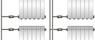
Temperature regulator on the radiator.
Temperature regulator on the radiator
The main advantage of using these devices is the ability to set a specific temperature regime for each individual room. For example, the temperature in the bathroom should be maintained around 25 degrees to reduce the effect of “dampness”. But in the sleeping areas there should be a slight coolness, about 17 or 18 degrees. At night, you can lower the overall temperature of your entire home by several degrees. And if there are no people in the house, you can completely lower the temperature to save money.
The temperature regulator on the radiator allows you to solve certain problems:
1. Possibility of adjusting the amount of heat generated by the battery. 2. Allows you to save on the number of consumable materials needed to maintain the network (in private homes with their own autonomous heating system). 3. Repair and disconnection of the battery is possible in a separate mode (without a general shutdown of the entire heating system).
The final choice of thermostat will depend on your financial condition and your own desires. For ordinary apartments, the best option would be a mechanical or semi-electronic device.