What pumps are used for boiler rooms?
Network pumps for boiler houses are most often centrifugal, equipped with an electric motor. By type they can be divided into: condensate, network, make-up, intended for raw water. You can also find this type of pump as a nutrient pump.
In water supply boiler systems, it is customary to install several devices at once that have the same characteristics . The pumps are connected in parallel, with one of them being the main one, and the second being a backup and starting as needed when the first one fails. However, it is also possible to operate two devices at once. In this case, the water pressure in the pipes remains the same as when operating one installation, but the water supply increases, the level of which becomes equal to the sum of the supply of each of the devices.
Pumps for boiler rooms can have enormous weight and dimensions
For boiler houses, the best option would be to install a centrifugal 1-stage pump type KM, a 1-stage unit type D with 2-way suction, or a multi-stage product type TsNSG. In addition, many professionals recommend installing condensate type KS units in the boiler room. In this case, the final choice depends on the specific requirements of the buyer, which, as a rule, are determined by the operating conditions of the future equipment.
Network pump and its purpose
This unit must pump the heating fluid in the supply pipeline at the optimal speed and pressure according to a temperature schedule of 150-70 C, depending on the outside air temperature. Their feature is the proximity of the cooling system circuit to its seals.
They are also distinguished by their productivity and high efficiency. Unit parts, for example, the casing and impeller, are made of durable cast iron alloy, which ensures wear resistance of the entire structure.
The reliability of the design development is confirmed by many years of experience in operating units in areas of high temperatures and water hammer. The circulation unit is unpretentious and does not require labor-intensive maintenance.
They are easily installed in a thermal system, have a simple design and a long guaranteed period of operation. Conditions for selecting a network unit - operating pressure, maximum temperature of heated water, quality of the working environment. They are intended for water with a concentration of mechanical impurities not exceeding 5 mg/l.
Feed pump and its purpose
This group of units works only with steam boilers with a pressure above 0.7 ati; they serve to fill the boiler with water to replace the amount that was spent on generating steam and purging salt water from the boiler.
This is a very important unit; the boiler’s performance depends on its reliability, and if it is not fed with water, overheating of the pipe heating surfaces will occur, followed by an explosion of the steam generator.
Therefore, the requirements of Kotlonadzor require the mandatory installation of at least two feeding units, with different movements of the working surface - one with a steam converter, and one with an electric source.
There are also requirements for the minimum performance of devices; each must provide 150% of the load of simultaneously operating boilers, that is, work with a significant margin.
If, according to the scheme, 3 or more units are installed in the boiler room, the type is selected in such a way that when the most powerful one comes out, the total performance of the pumps remaining in operation provides 120% of the rated load of the boilers. Electric centrifugal and piston steam pumps are used.
Raw water pump
This group of pumps is used in a chemical water treatment system. Their task is to take the environment from the raw water tank and direct the water for chemical purification from hardness salts and suspended solids; after processing, it enters the chemically purified water tank or deaerator to remove excess oxygen.
Typically, these are units of low power and operating pressure, since they operate in a closed circuit of a pipeline system that does not have large hydraulic losses.
Its operation can be carried out by the HVO operator manually, through the “Start” button, or by an automation system using water level sensors in the tank. The selection is made according to the design capacity of the chemical water treatment system, taking into account 100% reserve.
If the raw water unit fails, the deaerator will not be fed, the reserves of which are usually enough for several hours of boiler operation; subsequently, the boiler will be stopped by the safety automatics due to the low water level in the deaerator.
Condensate
Condensate pumps are used at large thermal facilities, for example, at thermal power plants, where they are used to pump condensate obtained from waste steam and supply it through a group of low-pressure heaters to deaerators, and in steam heating circuits of industrial enterprises, when it is necessary to pump waste condensate from consumers to the boiler room.
Nutritional devices
Nutritional devices
Feeding devices are designed to supply feed water to the boiler. They are critical elements of the entire installation, ensuring the safety of its operation. Feeding devices have a number of requirements imposed by the rules of Gosgortekhnadzor.
Feeding devices must have a manufacturer's passport and provide the required flow of feed water at a pressure corresponding to the full opening of the operating safety valves installed on the boiler. The water supply to steam generators operating at different pressures (difference in operating pressures is more than 15%) must be supplied from various feed devices.
Centrifugal pumps are used as feeding devices for supplying water to steam boilers of industrial installations, and piston pumps with electric and steam drive are used for small installations. Electrically driven centrifugal pumps are called electric pumps, while steam driven ones are called turbopumps. For piston steam pumps, steam engines are used as a drive.
The water supply devices for industrial steam boilers consist of at least two pumps with an independent drive (one with an electric drive, the other with a steam drive). The total productivity of electric pumps must be at least 110%, and that of steam-driven pumps - at least 50% of the rated steam productivity of all boiler units in operation. With two independent power sources, it is permissible to install all pumps only with an electric drive. Water is supplied to hot water boilers by network pumps. In this case, two pumps are installed: one working and one reserve. There are also two make-up pumps installed: a working one and a reserve one.
Boiler feed pumps are selected from the catalog based on total pressure and performance. The feed pump must create a total head (m water column), determined by
where pb is the highest possible excess pressure in the boiler drum, m of water. Art. рд — excess pressure in the deaerator, m of water. Art.; Hs is the total resistance of the suction and pressure tract of the feed installation, m of water. Art.; H is the difference in water levels in the boiler drum and the deaerator, m.
The main characteristics of a centrifugal pump are productivity (m3/h), total head (m water column), power consumption, as well as efficiency (%) and rotation speed (rpm). Typically, the catalogs of pump manufacturing plants provide a graphical dependence of the total pressure, efficiency, power consumed by the electric motor on the pump performance at different speeds. Power consumed by a centrifugal pump (kW), where Q is the pump capacity, m3/h; Np—total pressure, MPa; ἠ-pump efficiency at full pressure, %; ἠmotor — electric motor efficiency, %.
In Fig. Figure 10-1 shows a schematic diagram of the feed plant of an industrial steam boiler. Operation of feed centrifugal pumps with a water flow rate less than 10-15% of the nominal is unacceptable, therefore, to protect the pump when the feed water flow rate decreases, a relief valve connected to the recirculation line is installed. The recirculation line is turned on when the pump starts and stops. After the pump, it is necessary to install a check valve that prevents the flow of water from the pipeline if the pump stops. When installing several pumps intended for parallel operation, their pressure characteristics must be the same.
Feed pumps should be placed 5-10 m below the deaerator feed water tanks to avoid rupture of the hot water flow due to its boiling. A vacuum is created in the inlet pipe of the pump, so the absolute pressure of water at the entrance to the pump is less than atmospheric. The lower the absolute pressure of water in the suction pipe of the pump, the lower its boiling point. Consequently, when water enters at a temperature of 100 °C and the pressure in the suction pipe of the pump is below atmospheric, boiling occurs.
The formation of steam bubbles leads to hydraulic shocks in the supply pipelines and disruption of the water supply to the pump, which can cause a boiler failure. When the water temperature is 70 °C, the centrifugal pump cannot draw water from the tank located below the pump. To avoid steam formation when the feed pump operates on hot water, its pressure at the pump inlet must be higher than the saturation pressure at a given water temperature.
An increase in pressure in the pump suction pipe is achieved by positioning the pump below the feed tank. The minimum water level in the feed tank relative to the axis of the feed pump (m) is determined by the formula
where hin is the required pressure in the pump inlet, including the velocity pressure, kPa; hg. c is the hydraulic resistance of the pipeline system from the feed tank to the pump, kPa; pH - pressure of saturated water vapor corresponding to its temperature in the suction pipe of the pump, determined from water vapor tables, kPa; pd is the excess pressure under which the water is in the feed tank, kPa.
The required pressure in the inlet pipe of the pump depends on its design and is given in the catalog at a water temperature of 20 ° C, depending on the pump performance (for centrifugal pumps at a rotation speed of 2900 rpm it is 80-100 kPa). The hydraulic resistance of the suction pipeline from the feed tank to the pump should be kept to a minimum. To achieve this, pipelines are kept short with a minimum number of turns, tees and fittings; The water speed in the calculation is assumed to be 0.5-1 m/s.
For steam boilers operating at a pressure of about 4 MPa, the elevation of the deaerator platform in relation to the pump installation elevation should be approximately 10 m, and for steam generators with a pressure of about 1.4 MPa - approximately 6 m.
In heating boiler houses, network and underflow pumps are installed, and in the presence of hot water boilers, additional recirculation pumps are installed.
Network pumps for water heating installations are selected according to the flow rate of network water per pressure, ensuring coverage of the hydraulic resistance of the network, network water heaters, condensate coolers, as well as hot water boilers, if installed. Network pumps are installed on the return line of network water and operate at a water temperature of no more than 70 °C.
Sub-fuel pumps are selected according to the flow rate that ensures replenishment of losses in the heating system. In closed heat supply systems, water leakage is assumed to be equal to 0.5% of the volume of water in the pipelines of the system with subscribers connected to it. In this case, the pump performance is selected based on double flow, taking into account the water supply in emergency situations. In open heat supply systems, the performance of make-up pumps is selected taking into account the coverage of the total water consumption at maximum consumption for hot water supply and leaks in the system. Sub-primary pumps must create a pressure that ensures overcoming the pressure in the return line in front of the network pumps, as well as the hydraulic resistance of the connecting pipelines and the makeup regulator. Recirculation pumps are installed in boiler rooms with hot water boilers for partial supply of hot network water to the pipeline supplying water to the hot water boiler. In accordance with SIiP P-35-76, the installation of recirculation pumps is carried out if the manufacturers of water heating boilers require a constant water temperature at the inlet or outlet of the boiler. The performance of the recirculation pump is determined from the balance equation of the mixing flows of network water in the return line and hot water at the outlet of the hot water boiler.
In Fig. Figure 10-2 shows a diagram of the installation of a recirculation pump and a regulator that maintains the required temperature of water supplied to consumers. Regulation of the temperature of the water entering the hot water boiler and the temperature of the water supplied to consumers is carried out as follows. The amount of water supplied by the recirculation pump is adjusted to obtain the required water temperature at the inlet to the hot water boiler. However, the temperature of the water leaving the boiler may be higher than the temperature required by consumers. To maintain the set temperature of water supplied to consumers, part of the water from the return line is directed through a jumper into the forward line. The amount of water taken from the return line into the forward line is regulated by the network water temperature regulator. In accordance with the diagram in Fig. 10-2, you can write the following equations:
Solving equations (10-4) and (10-5) together, we obtain
where Gw.k is the amount of network water passing through the hot water boiler, t/h; Grets — the amount of network water supplied by the recirculation pump, t/h; Gc.v — amount of return network water supplied by the network pump, t/h; Grreg - the amount of return network water supplied by the regulator through a jumper to the direct water line sent to consumers, t/h; t'с.в — temperature of network water in the return line, °C; t'v.k - water temperature at the outlet of the hot water boiler, °C; t'v.k - minimum permissible water temperature at the inlet to the hot water boiler, °C.
From equation (10-7) it is clear that at t'c. in = t'in. The amount of water supplied by the recirculation pump is zero. As the temperature of the network water decreases, the amount of water supplied by the recirculation pump increases. As the temperature of the water after the hot water boiler increases, the amount of water supplied by the recirculation pump decreases, but the flow of return network water through the jumper increases. This reduces the water flow through the hot water boiler, which is acceptable up to certain limits, at which there is a danger of water boiling in the boiler. Therefore, the water temperature after the hot water boiler t'w.k should be taken no higher than such values at which the water flow through the hot water boiler will be below the permissible minimum. After calculating Gpec, using equation (10-4), the value of Gv.k is checked using equations (10-5) and (10-6).
The recirculation pump must create a pressure capable of overcoming the hydraulic resistance of the water heating boiler and recirculation pipelines. The pressure created by the recirculation pump is usually 150-250 kPa.
Domestic factories produce a wide variety of centrifugal pumps with electric and steam drives (electric pumps and turbopumps). Table 10-1 shows the characteristics of pumps used as feed, network, make-up and recirculation pumps.
Network pump design and principle of operation
SE type pumps have a horizontal design. These are units that operate thanks to centrifugal force. For this purpose, an impeller with two-way motion is installed in a spiral casing with a horizontal split. The rotor rests on external-type rolling bearings with forced or ring lubrication. The drawing of the network pump forces you to pay attention to the mechanical seals of the shaft seal. They are supplied with a locking and cooling fluid; this “jacket” is mandatory for units of any power.
The working shaft of the network unit is located horizontally, this is typical for all SE models. The casing connector is also located in a horizontal plane, which provides easy access to pump parts and their quick replacement in the event of an accident or scheduled repair. These pumps are available in single-stage and multi-stage types.
The slot seals of the units are made of corrosive alloys; chromium steel is used for the impeller. The body and covers are cast from gray cast iron, which allows the equipment to be used in the climatic conditions of the Far North.
Structure of the network pump symbol
SEN 1250-140 UHL3
Where,
- C – network;
- E – electric;
- N – pump;
- 1250 – nominal flow, m3;
- 140 – nominal pressure, m;
- UHL3 – climatic version.
Feed pumps (PE, AN, TsVK)
Centrifugal vortex pumps TsVK are two-stage, cantilever pumps driven by an engine through a coupling. The first stage is centrifugal, the second is vortex. These pumps are designed for pumping water and similar neutral liquids with a solid content of no more than 0.01% by weight and a size of no more than 0.05 mm. The temperature of the pumped liquid is up to 105°C. Pumps are used to supply feedwater to low-power steam boilers. The PE feed pump is designed to supply water to stationary steam boilers of thermal power plants operating on organic fuel (PE 90-180 and PE 90-110 - to supply feed water to steam generator units used for the development of oil fields). The AN 2/16 pump is a horizontal, double-piston, quadruple-action pump. Designed for pumping clean fresh water as part of low-capacity boiler units. The temperature of the pumped water is from 5°C to 80°C.
| Model | Supply m3/h | Head m | Engine kW/rpm | Weight. Kg | Dimensions | Price with VAT | |
| PE 65-28 | 65.0 | 290.0 | 110/2945 | 1990 | 1630x810x960 | Price on request | Order |
| PE 65-40 | 65.0 | 440.0 | 132/2960 | 2100 | 2570x1310x840 | Price on request | Order |
| PE 65-53 | 65.0 | 580.0 | 200/2965 | 2170 | 3185x1330x963 | Price on request | Order |
| PE 90-110 | 90.0 | 1100 | 500/2970 | 6860 | 3185x1330x963 | Price on request | Order |
| PE 90-180 | 90.0 | 1900 | 800/2970 | 8920 | 5015x1390x1615 | Price on request | Order |
| PE 100-32 | 100.0 | 330.0 | 160/2960 | 2400 | 2615x310x1345 | Price on request | Order |
| PE 100-53 | 100.0 | 580.0 | 315/2980 | 4020 | 3590x1285x1070 | Price on request | Order |
| PE 145-30 | 145.0 | 293.0 | 200/2960 | 2400 | 3590x1285x1070 | Price on request | Order |
| PE 150-53 | 150.0 | 580.0 | 500/2980 | 5925 | 3800x1175x1435 | Price on request | Order |
| PE 150-63 | 150.0 | 700 | 500/2980 | 4450 | 3913x1610x1450 | Price on request | Order |
| PE 160-140 | 160.0 | 1400 | 1000/2973 | 2400 | 3942x1280x1110 | Price on request | Order |
| PE 380-185-5 | 380.0 | 2030 | 3150/2975 | 20035 | 8370x1635x1900 | Price on request | Order |
| PE 380-200-5 | 380.0 | 2190 | 3150/2975 | 20760 | 8370x1635x1900 | Price on request | Order |
| PE 600-300-4 | 600 | 3290 | 8000/6300 | 30670 | 8800x2700x2300 | Price on request | Order |
| TsVK 4/112 | 14.4 | 112.0 | 22.0/3000 | 303.0 | 1322x360x545 | RUB 133,000 | Order |
| TsVK 4/112 | 14.4 | 112.0 | 18.5/3000 | 275.0 | 1225x360x480 | RUB 124,000 | Order |
| TsVK 5/125 | 18.0 | 125.0 | 30.0/3000 | 313.0 | 1362x360x545 | 140,000 rub. | Order |
| TsVK 5/125 | 18.0 | 125.0 | 22.0/3000 | 303.0 | 1322x360x545 | Price on request | Order |
| TsVK 6.3/160 | 22.7 | 160.0 | 37.0/3000 | 385.0 | 1375x406x615 | Price on request | Order |
| TsVK 6.3/160 | 22.7 | 160.0 | 30.0/3000 | 313.0 | 1362x360x545 | 140,000 rub. | Order |
| AN 2/16 | 2.0 | 160.0 | 1.5/1500 | 110.0 | 710x350x450 | Price on request | Order |
Symbols of feed pumps:
PE 380 – 185 – 5 UHL3
- PE – Electric feed pump
- 380 — Nominal flow, m3/hour
- 185 — Pressure reduced by 10 times, m
- 5 — Pump version
- UHL3 - climatic version and placement category
TsVK 6.3/160 U2
- TsVK — circulating vortex cantilever
- 6,3 — feed, l/s
- 160 — head, m
- U2 - climatic version and placement category
AN 2/16 UHL4
- AN – pumping unit
- 2 — feed, l/s
- 16 — head, m
Scope and characteristics
Characteristic features of network pumping devices are ease of installation and low maintenance. Materials such as high-quality steel and gray cast iron, from which such equipment is made, help to increase the safety margin and durability of the pump. The technical characteristics of network pumps allow them to work with predominantly clean water, which should not contain solid parts with a diameter greater than 0.2 mm, as well as more than 5 mg/l of mechanical impurities.
Most often, network pumping devices are used to create water circulation in heating networks, as well as to service a boiler (heating) network installation. Such units are manufactured both with one gear and in a 2-stage version. The drive operates using electric power units (motors). They look like horizontal pumps.
The units also include in their device:
- housing with horizontal connector;
- impeller with double-sided water inlet;
- bearings, shaft and end sealing elements;
- chambers for end seals and flanges for mounting bearings installed in the housing;
- rolling bearings that support the rotor;
- roller or ball support bearing for drive;
- bearing for the radial axis.
Several identical pumps are installed in parallel in boiler rooms.
The average water supply of devices for boiler houses is 450-500 cubic meters per hour, the pressure is around 50-70 m, and such a parameter as inlet pressure varies within 16 kilograms per square centimeter. Pumps whose purpose is to circulate hot water in small heating systems have lower power and performance indicators, but they also cost an order of magnitude cheaper.
The scope of application of network products is not limited only to heating systems, in particular boiler rooms. This equipment is successfully used for supplying fuels and lubricants to bases, warehouses and industrial enterprises, for pumping reagents into water treatment plants, as well as in water treatment systems designed for pumping water into water supply systems when the pressure level in pipes drops. At the same time, such equipment is also used for cleaning tanks contaminated with sludge, as well as storage facilities for substances such as fuel oil.
Technical characteristics of the product “Network pumps”
| Capacity (feed) | 500…5000) m³/hour |
| Pressure | 55…180 m |
| Efficiency no less | 87 % |
| Designated service life is not less than | 20 years |
| Motor speed | 1500, 3000 rpm |
| Electric motor power, no more | 3150 kW |
Dimensions and weight
The lineup
| Name | Productivity, m3/hour | Head, m | Temperature of the pumped medium, C° | Seal type: M-lip, T-face, DT-double face | Nutrition | Engine power, kW | Rotation speed, rpm |
| Network pumps | 55…180 | 3150 | 1500, 3000 |
Hello student
The feed system closes the boiler-turbine steam power cycle, providing the possibility of returning exhaust steam to the boiler in the form of feed water. This system has four main elements: boiler, turbine, condenser and feed pump. The boiler produces steam, which is fed to the turbine, and after the steam has consumed energy, it is sent to the condenser. There the steam turns into water (condensate), which is supplied by a feed pump to the boiler.
In practice, the system also includes a number of elements, such as a waste tank, into which condensate from the condenser is discharged and thanks to which a certain pressure is provided at the inlet to the feed pump. To compensate for water leakage from the system or to create some excess feed water in the system, a compensation tank is provided. If the feed system serves an auxiliary boiler, for example, on a ship, then the waste tank or warm box communicates with the atmosphere. Such a system is called open. In high-pressure water-tube boilers, the feed system in no part communicates with the atmosphere, and such a system is called closed.
OPEN NUTRIENT SYSTEM
A diagram of the open feed system for the auxiliary boiler is shown in Fig. 5.1. Exhaust steam from various auxiliary mechanisms is condensed in a condenser, which is cooled by sea water. The pressure in the condenser can be maintained at atmospheric or slightly below atmospheric. The condensate from it flows into a warm box equipped with filters. If the condenser is operating under a slight vacuum, a condensation pump is used to supply water to the warm box. The warm box may also receive condensate from systems in which it can become contaminated, for example from fuel heaters, from the fuel heating system in tanks, etc. Contaminated condensate can be detected either at the outlet of the condensate cooler, or by monitoring the control tank.
Rice. 5.1. Open feeding system:
1 - nutrient tank; 2 - pipeline for draining excess water: 3 - warm box with filters; 4 - capacitor; 5—valves for supplying steam to mechanisms and devices;
6 — feed water regulator; 7 - boiler; 8 — auxiliary feed pump; 9 — main feed pump; 10 — feed water heater
A monitoring tank, if installed, allows such monitoring and if contaminated condensate is detected, it is directed to the contaminated wastewater tank. The warm box contains deflectors for preliminary separation of oil or fuel from condensate or feed water. The water is then passed through carbon or fabric filters to complete the purification. Excess water from the warm box is transferred to the feed water tank, from where the feed system will be replenished if necessary. Water is drawn from the warm box by the main and auxiliary feed pumps. A feedwater heater can be installed in the main feed system. The heater can be a surface type, in which only water is heated, or a contact type, where in addition to heating the water, it is also deaerated. Deaeration is the process of removing air containing oxygen from feed water, the presence of which can cause corrosive processes in the boiler. To regulate the water supply to the boiler and maintain the required level in it, a feedwater regulator is installed.
The system described above is a typical system, and there may be some differences in each specific installation.
CLOSED NUTRIENT SYSTEM
In Fig. Figure 5.2 shows a diagram of the closed feed system of a high-pressure water-tube boiler supplying steam to the main steam turbine.
Steam from the turbine enters the condenser, where a high vacuum is maintained. A regenerative type condenser is used here, in which condensation is carried out with a minimum temperature difference. The condensate pump pumps condensate out of the condenser and delivers it to the air ejector.
Passing through the ejector, the condensate is heated. The air ejector, which serves to pump air out of the condenser, is a steam jet ejector.
Rice. 5.2. Closed nutritional system:
1 — feed water tank; 2 condensate pumps; 3— capacitor; 4 - pipeline for air and gases; 5 — air ejector; 6 — sealing system capacitor; 7 - recirculation pipe; 8— valves for supplying steam to mechanisms and devices; 9 — drainage condensate cooler; 10 — low pressure heater; 11—economizer; 12 - boiler; 13 — steam superheater; 14 — high pressure heater; 15 — feed pumps; 16 — deaerator; 17—drainage pump; 18 - atmospheric waste tank
The condensate is then passed through the sealing system condenser where it is further heated. This condenser condenses the steam from the turbine seal system and drains the condensate into the waste tank. Next, the main system condensate passes through a low-pressure heater, which is fed by steam from the turbine extraction. The use of all of the above heaters improves the efficiency of the installation due to regenerated heat, and the increase in water temperature contributes to its deaeration.
In the deaerator, direct contact of feed water with steam occurs, where they actually mix. When mixed, the water is heated and all dissolved gases, in particular oxygen, come out of it. The lower part of the deaerator is a container from which water is taken directly by one of the feed pumps that supplies water to the boiler.
The water then flows to the high pressure feedwater heater, then to the economizer, and from there to the steam header. The system has a waste tank connected to the atmosphere to drain excess feed water into it and a feed tank, from where, if there is a lack of water, the feed system will be replenished. The waste tank also receives condensate from many auxiliary systems, such as the turbine seal system, condensate from the exhaust working steam of air ejectors, etc. To ensure the passage of feed water through the air pump and seal system condenser at low power conditions and during maneuvering of the vessel in The system is equipped with a recirculation jumper.
This diagram is also typical, and there may be some differences in it for each specific installation.
AUXILIARY NUTRITION SYSTEM
The system is designed to generate steam from condensate from auxiliary mechanisms and devices; it can be performed either separately - in the form of an open or closed system, or in conjunction with the main supply system, forming part of it.
In cases, for example, when deck mechanisms use a steam drive, a condenser operating at a pressure close to atmospheric is used to condense the exhaust steam (Fig. 5.3). The condensate is supplied by a condensate pump to the air ejector, after passing through which the water enters the main supply line between the sealing system condenser and the drainage condensate cooler. For operation at low power, recirculation is provided, and to regulate the water level in the condenser there is a level regulator.
Rice. 5.3. Auxiliary nutritional system:
1 - level regulator; 2—recirculation pipe; 3 - auxiliary capacitor; 4 — air ejector 5 — condensate pump; 6 — drainage condensate cooler; 7 — sealing system capacitor; I - supply of exhaust steam from auxiliary mechanisms and devices
Rice. 5.4. Steam generator feed system:
1 — feedwater heater; 2 — steam generator; 3 - pipeline for low pressure steam; 4 - valves for supplying steam to auxiliary mechanisms and devices; 5 — tank of contaminated condensates; 6 - feed pumps; I—discharge of condensate into the main feed system; II - steam supply
If there is a risk of contamination of the feedwater in the installation, a separate system can be created for the steam generator (Fig. 5.4). Low pressure steam from the steam generator is supplied for various ship needs, such as fuel heating, and the condensate is returned to the warm box. Feed pumps supply water to the feed water heater, which simultaneously serves as a cooler for the condensate obtained from the heating steam of the steam generator. From here the water goes directly to the steam generator.
Many companies produce nutritional systems in a modular design, that is, various elements of the system are mounted on a single foundation. Sometimes the entire set of mechanisms and devices or some part of it is located there.
ELEMENTS OF THE NUTRIENT SYSTEM
Capacitor.
This is a heat exchanger in which latent heat is removed from exhaust steam, as a result of which the steam turns into condensate, which is sent back to the boiler. Condensation should be carried out with minimal subcooling, i.e. the temperature of the condensate should differ minimally from the temperature of the steam. The condenser is designed in such a way that various gases and vapors that are released during condensation of water vapor are removed from it.
In Fig. Figure 5.5 shows an auxiliary capacitor. The body, round in cross-section, is closed on both sides with lids designed so that the sea water in the condenser makes two passes. Protectors are installed in the water cavities of the covers, which are necessary to protect against electrochemical corrosion. Steam enters the condenser from above in the central part of the housing and through the windows in the inlet box located under the casing, it is divided into two streams. Steam condenses on the surface of the tubes through which sea water passes. To fasten the tubes, a diaphragm is arranged along the length of the middle of the condenser, which in turn is secured using anchor bolts. Condensate accumulates in a sump located under the bundles of water tubes. Provision is made for pumping out air, gases and vapors released during condensation of water vapor.
The main condensers operating in conjunction with the main steam turbines are regenerative type condensers. Part of the steam in them passes through the tubes and comes into contact with the condensate in the sump. The condensate thus has the same temperature as the steam, which increases the efficiency of the condenser. In Fig. Figure 5.6 shows one of the regenerative capacitor projects. In its center there is a channel through which steam passes to the settling tank and, condensing, heats the condensate.
Rice. 5.5. Auxiliary capacitor:
1 — condensate return pipe; 2 — protectors; 3 - manhole with inspection hatch; 4 - anchor bolt; 5 — inlet water box; 6 — flange for supplying circulating water; 7 — inspection hatches; 8 — water drainage flange; 9 — plugged fitting; 10 — casing at the steam inlet to the condenser; 11 — wet steam inlet pipe; 12 — pipe from the boiler top blowing valve; 13, 27 — pipes for the thermometer; 14. 30 - pipes for the tap of alkaline additives; 15 - air valve; 16 — pipe for a vacuum gauge; 17 — water box; 18 — spare steam pipe; 19 — capacitor body; 20 - water measuring glass; 21—sump; 22 — air exhaust pipe; 23 - diaphragm; 24 - tube plate; 25 dividing partition; 26— drain plug; 28 — drain valve pipe; 29 condensate exit cabins
rice. 5.6. Regenerative type capacitor:
1 - tubes; 2 — capacitor body; 3—gas and air suction pipe; 4 - outlet partition; 5 - central channel; 6 — condensate level; I—exhaust steam; II - steam to the condensate drain pump
There are partitions for the released gases and vapors. A plurality of tubes are installed in the tube sheets on both sides, supported by intermediate supports. The intake water in the tubes makes two passes.
Condensate pump.
This pump is designed to pump water from a condenser in which a vacuum is maintained. At the outlet of the pump, pressure is created to supply water to the deaerator or to the feed pump. By design, condensate pumps are usually centrifugal, two-stage, with a vertical shaft. The design of the pumps is described in Chapter. 6. For normal operation of these pumps, a certain minimum suction head is required, as well as a certain controlled level of condensate in the condenser. The first stage of the pump receives water, which almost boils under the vacuum conditions that exist in the suction pipe. Water enters the second stage with some positive pressure, and at the exit from the second stage the water has a given pressure.
In condensers where the condensate level may fluctuate or where the sump is almost dry, self-regulating condensate pumps can be used. Self-regulation in them occurs during cavitation, which occurs when the suction pressure drops to a very small value. Cavitation is the process of formation and destruction of steam bubbles, as a result of which the pump flow drops to zero. As the suction pressure increases, cavitation disappears and the pump begins to supply water again. During cavitation, various damages usually occur (see Chapter 11), but at the low pressure that exists in condensate pumps, no damage is observed. In addition, the pump impeller can be designed in such a way that supercavitation will occur, i.e., the destruction of bubbles after they exit the impeller.
Air ejector.
Using an air ejector, air and vapors are sucked out from the steam condensing in the condenser. If air is not removed from the system, corrosion may occur in the boiler. In addition, the presence of air in the condenser would complicate the condensation process and lead to the creation of back pressure in it, due to which it would be necessary to increase the steam pressure at the turbine outlet, which leads to a decrease in thermal efficiency.
In Fig. Figure 5.7 shows a dual two-stage air ejector. In the first stage, this steam jet ejector acts as a pump, sucking air and gases from the condenser. Then the steam-air mixture enters the condensing part, where feed water circulates. The feedwater is heated and most of the vapor is condensed. The condensate from here descends into the main condenser, and the vapors and gases pass into the second stage of the ejector, where the process is repeated. The remaining air and gases after passing through this stage are released into the atmosphere through a vacuum check valve.
Rice. 5.7. Air ejector:
1—rolled pipe ends: 2—spacer tube: 3—anchor bolt; 4 - first stage capacitor; 5 — capacitor body; 6 — sliding support; 7 — steam nozzle of the first stage; 8 — nozzle holder; 9 — steam nozzle of the second stage; 10—separating partition: 11—second stage capacitor; 12 — condenser tubes; 13 — water box partition; I, II - air inlet and outlet: III, IV - cooling water inlet and outlet
Rice. 5.8. Drain condensate cooler:
1 — box cover; 2 - distribution box, 3 - air valve: 4 - safety valve; 5 - pressure gauge; 6 — U-shaped tubes; 7 - anchor bolts; 8 — support paw; 9 — body; 10 - diaphragm; 11— drain valve; 12 — dividing partitions; I—condensate outlet; II - steam inlet; III, IV - feedwater outlet and inlet
Feedwater in both stages circulates through U-shaped tubes. Each stage has two ejectors, although the operation of one of them is sufficient for satisfactory operation of the installation.
Heat exchangers. The compaction system condenser, drain condensate cooler, and low-pressure feedwater heater are all tube-type heat exchangers. In each of them, in one way or another, heat is removed from the exhaust steam and, thanks to this, the feed water circulating in the tubes of the apparatus is heated.
The condenser of the turbine sealing system receives steam, gases and air, which are cooled by water, and the steam condenses. The condensate is returned to the system through a loop water seal or steam trap, and the remaining air and gases are released to the atmosphere. The feedwater in the heat exchanger flows through U-shaped tubes.
Exhaust steam from various auxiliary mechanisms and devices enters the drain condensate cooler, in which the steam is condensed and the condensate is returned to the feed system.
1—water; 2 - steam; 3—water jets; 4 — neck cover; 5 — air pipe pipe; 6 - inlet water manifold; 7 — nozzles; 8 — partition of the upper water-cooling chamber; 9 — partition of the lower water-cooling chamber; 10 — guide cone; 11 — deaerator cones; 12 — body; 13 - guide; 14 — manhole cover; 15 — paws; I— water drain; II - steam supply; III—water supply.
Circulating feed water passes through the apparatus through straight tubes fixed in tube sheets. Diaphragms and partitions serve to direct the flow of steam in the apparatus and at the same time to fasten the tubes (Fig. 5.8).
The low-pressure feedwater heater typically receives steam from the low-pressure turbine exhaust. Heating the feed water promotes the deaeration process. By extracting steam from the low-pressure turbine, not only does the thermal efficiency of the installation improve, but it is also possible to reduce the height of the blades of the last stages, since the mass of the steam flow is reduced. These devices can use both straight and U-shaped tubes, and in the water part the tubes can be single-pass or multi-pass.
Deaerator.
The deaerator completes the process of removing air and vapor from the feed water, which began in the condenser. At the same time, the deaerator also serves as a feedwater heater, but in it the water and heating steam come into direct contact. The feed water is heated to a temperature close to the boiling point, at which all dissolved gases are released from it, and these gases are immediately removed.
In Fig. Figure 5.9 shows one of the deaerator designs. Feed water is supplied to the deaerator through several spray nozzles. The sprayed water has a very large contact surface with the heating steam. Most of the water falls from above onto the surface of the upper cone, where the process of heating it with steam continues. Then the water enters the central channel and leaves it through a small hole, which acts as an ejector that sucks in steam along with water. Feed water and working steam condensate accumulate in a storage tank that makes up the lower part of the deaerator. The working steam enters the deaerator, passes through it, heating the feed water, and, turning into condensate, mixes with the feed water. The released gases exit through the air pipe into the steam-air mixture condenser. The steam that gets there along with the air condenses and returns to the system. Feed water circulates in the tubes of the steam-air mixture condenser, and from there it immediately enters the deaerator.
The temperature of the feed water in the deaerator is very close to the temperature of the steam at the pressure existing in the deaerator, and therefore it is possible, with any drop in pressure, to instantly convert water into steam. This can lead to “gassing”, i.e. the formation of steam in the suction part of the feed pump. To avoid this, the deaerator is located in the upper part of the engine room, thereby providing a certain positive pressure at the inlet to the feed pump. But sometimes a pump-out or booster pump is installed directly at the outlet of the deaerator.
Feed pump.
Designed to create feedwater pressure at which it enters the boiler. For auxiliary boilers that consume a small amount of feed water, a steam-driven piston pump can be used as a feed water pump. A pump of this type is described in Chap. 6. Another type of pump that is often used in packaged boiler installations is the electric feed pump. This is a multi-stage centrifugal pump driven by a DC motor.
In installations with high-pressure water-tube boilers, turbine-driven feed pumps are used. Shown in Fig. 5.10, a two-stage horizontal centrifugal pump driven by an active turbine is placed in a common housing with it. Steam to the turbine comes directly from the boiler and exits into the main line, from which the steam can be directed to heat water. The pump bearings are lubricated with filtered water, which is taken after the first stage of the pump. The pump is equipped with a regulator to maintain the set pressure and a limit switch that is activated when the rotation speed is exceeded.
Rice. 5.10. Turbine driven feed pump:
1 — steam outlet flange; 2— messenger valve socket; 3— release mechanism of the limiting speed regulator; 4— turbine disk; 5 — turbine shaft coupling bolt; 6 — replaceable cover, 7 — Hirs coupling; 8 - partition; 9 — nozzle box; 10—pipe to the pressure gauge in the nozzle; 11 — Venturi tube; 12 — water discharge pipe; 13 — load of the limiting speed regulator; 14 - shaft; 15 — balancing piston; 16 — ring section; 17 — pump impellers; 18—pipe to the water pressure gauge on the receiving water pipe; 19 — channel to the balancing piston; 20 — receiving water pipe; 21 - water intake; 22 — cocking lever for the maximum speed regulator; 23 — emergency shutdown handle
High pressure feed water heater.
The heater is a tubular type and is used for additional heating of feedwater before entering the boiler. Since the water pressure after the feed pump increases, it becomes possible to additionally heat the water without boiling it. The water entering the heater circulates through U-shaped tubes, washed by heating steam. There are diaphragms that serve to secure the tubes and to direct the flow of steam inside the apparatus. To ensure complete condensation of the steam, a condensation trap is installed. Steam from the turbine exhaust is used as a heater.
Maintenance of the nutritional system.
During continuous operation of the installation in operating mode, it is necessary to maintain equality of the masses of feed water introduced into the boiler and the steam leaving it, while the water level in the boiler must be maintained within normal limits.
Protectors made of low-carbon steel are installed in the water cavities of the condenser covers, where sea water passes. They need to be replaced periodically. At the same time, the tubes are inspected to detect erosion, which may occur if the circulation rate is very high. Leaks in the water tubes can lead to contamination of the feed water, so if there is even the slightest suspicion of a leak, the capacitor should be tested. In ch. 7 shows the scope and content of work when testing capacitors.
Condensate pump seals should be checked regularly to prevent air from entering the system. For all types of pumps, a small amount of water leaking through the sealing device to help lubricate the bearing and seal is acceptable and normal.
An air ejector will experience reduced performance if its nozzle becomes coated or eroded, so the ejector nozzles should be inspected regularly and replaced if necessary. You also need to periodically check the tightness of the ejector housing and the tightness of the vacuum valve.
You should periodically check for leaks in the heat exchangers and ensure the cleanliness of the heat exchange surfaces.
Turbine-driven feed pumps must be started with the discharge valve closed so that the pressure in the discharge line rises sharply and hydraulically equilibrates with the pressure in the boiler. Turbine drives of pumps must be warmed up before operation with the drain valves open and put into operation after the drain valves are closed. It is necessary to regularly check the operation of the load limit regulator. It is also necessary to control the axial clearances in the turbine, for which special probes are used.
Download abstract: You do not have access to download files from our server. HOW TO DOWNLOAD HERE
Archive password: privetstudent.com
How to choose a network pump?
The feed pump for water circulation and heat boilers is selected based on the following nuances:
- the amount of heat that will be required to heat the building;
- calculation of the thermal insulation value of walls;
- climatic conditions of the region where the consumer lives;
- whether there are window frames in the building and how many there are;
- selection is also carried out taking into account the surface structure of the ceiling and floor.
In order to correctly calculate the device for water circulation, the choice of unit for thermal boilers is carried out with the choice of coolant. The selection of this element includes an analysis of the properties of viscosity, heat transfer, and heat capacity. In order for the operation of thermal boilers to be most efficient and balanced, network pumps are selected taking these parameters into account.
Features of use
Calculation and selection of a device for water circulation must be carried out taking into account all aspects. For example, if you buy an SE 2500 60 pump, and the power of your system is less, then the circulation unit will consume an order of magnitude more electricity. In addition, the SE 2500 60 pump, when operating in a low-power system, will provoke noise in the pipes, and this indicates that the feed pump was selected incorrectly.
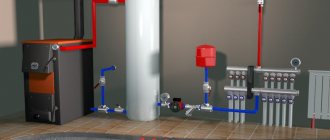
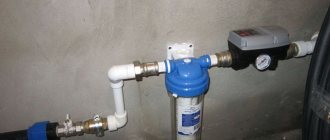
An example of installing a network pump in a boiler room
However, noise in pipes is not always a consequence of incorrect operation of the water circulation device for the boiler room. Often noise occurs when an air lock has formed in the batteries. The process of removing air pockets is carried out using specialized valves, but this must be done before you start heating the house.
In the case when there is no air in the pipes and the system as a whole is running, the feed pump must run for some time, after which the process of removing the air lock is repeated again. Then the pump SE 800 or another brand should be adjusted again, however, most companies produce circulation devices with an automatic adjustment function. When the air lock is completely removed and the device is adjusted, the boiler room will be ready for full operation.
If your circulation steam pump is unregulated, then the first start of water should be made at the lowest pressure. Adjustable SE pumps for thermal boilers only need to be configured so that the release function is turned on - then the device will independently regulate the pressure. Modern water circulation units are equipped with a metal housing and ceramic bearings. Thanks to this, the operation of the unit will be almost silent.
Power calculation
Calculation and selection of power available to SE pumps is carried out by analyzing the heat needs of a house or room. This indicator is calculated taking into account the coldest temperatures of the climate zone in which the consumer lives.
Network pumps installed in the boiler room
Below we will tell you how to correctly determine the necessary indicators so that the pressure during operation of the device is most optimal and can warm up the entire house.
Warm
Heat calculation is the first thing you need to do when you select PE feed pumps. First of all, in order for the operation of thermal boilers to be more efficient, it is necessary to calculate the area of the building that it will heat. In accordance with international standards, the calculation is made as follows:
- For one square meter of a house in which there are two apartments, you will need a SE 800-100 W energy device or from another manufacturer.
- For multi-storey buildings, you can purchase a circulation pump SE 1250 70, a device SE 500 70 or any other circulation pump with a power of 70 W.
If the house was built in violation of the standards, then when calculating the power, the part of the building with an increased level of heat consumption should be used. If your house or building is equipped with additional thermal insulation, then drives with a consumption of 30 to 50 W/m² can be used for thermal boilers of these systems. In the countries of the post-Soviet space, utility companies carry out calculations according to the following principle:
- Small buildings (1-2 floors) consume about 170 W/m² if the air temperature is 25 degrees below zero. If the temperature drops to -30, then this figure increases to 177 W/m².
- If the building is multi-story, then the heat boiler drives will consume about 97-102 W/m².
Now regarding the choice, you need the performance that the drives should have.
Network pumps
This can be a pump SE 1250 70, a device SE 500 70 or any other, the performance is calculated using the formula G=Q/(1.16xDT), where:
- 16 is an indicator of the specific heat capacity of the liquid.
- DT is the difference in temperature conditions in the supply and return pipelines. Typically this figure is about 20 degrees. In low-temperature systems it is reduced to 10%, and if the building is equipped with a heated floor system, then only 5 degrees.
Recommendations for selection
There are a fairly large number of recommendations regarding choosing the most suitable model. The main operational qualities are the following:
- Power. This parameter depends on the design features, as well as some other points. Some pumps operate on energy; power determines the degree of electrical consumption.
- Performance and throughput are also important. The throughput capacity depends on the design features and is selected depending on the diameter of the pipe.
- The type of materials used in manufacturing is also important. Industrial versions are made using stainless steel, which can withstand exposure to moisture and some chemicals. Household and cheap models are made using plastic, since such material is lightweight, inexpensive, and resistant to environmental influences.
When choosing a suitable pump model, you need to pay attention to the popularity of the brand. Only products from well-known manufacturers are quite expensive.
Pressure calculation
In addition to the above parameter, the SE 1250 140 pump or any other drive must create the required pressure, that is, pressure. The pressure indicator must be such that the liquid can circulate through the system without problems. When designing a new building, it will be difficult to calculate pressure calculations so that the result is accurate. As a rule, all information is indicated in the service book for the SE 500 pump or another brand. How to calculate pressure using the formula H=(RxL+Z)/p*g:
- R – resistance indicator in a flat pipe;
- L – total length of the pipeline;
- Z – indicator of reinforcement resistance;
- p – density;
- g is the gravitational acceleration indicator.
Network pumps type SE
| Pump unit size | Pump parameters | Motor parameters | Dimensions of the pump unit, mm | Ma, kg | |||||
| Q, m3/h | H, m | Type | Nd kW | n, min-1 | L | B | H | ||
| SE 500-70-16 | 500 | 70 | 5AN280A2 | 160 | 2950 | 2300 | 1050 | 1065 | 2328 |
| SE 800-55-11 | 800 | 55 | 5AN315A4 | 200 | 1450 | 2485 | 1155 | 1102 | 2710 |
| SE 800-100-8 | 800 | 100 | 5AN355A2 | 315 | 2950 | 3720 | 1695 | 1500 | 4840 |
| SE 800-100-11 | 800 | 100 | 5AN355A4 | 315 | 1450 | 3995 | 1370 | 1840 | 5250 |
| SE 1250-70-11 | 1250 | 70 | 5AN355A4 | 315 | 1450 | 3080 | 1236 | 1235 | 4200 |
| SE 1250-140-8 | 1250 | 140 | n/a | 800 | 2950 | 4073 | 1695 | 1515 | 5860 |
| SE 1250-140-11 | 1250 | 140 | A4-400U4 | 630 | 1450 | 4375 | 1530 | 2220 | 7365 |
| SE 2500-60-8 | 2500 | 60 | A4-400U4 | 630 | 1450 | 3995 | 2345 | 2070 | 7980 |
| SE 2500-60-11-1 | 2500 | 60 | A4-400U4 | 630 | 1450 | 3995 | 2305 | 2070 | 7210 |
| SE 2500-180-8 | 2500 | 180 | 4АЗМ1600/6000 | 1600 | 2950 | 4770 | 1975 | 1710 | 8580 |
| SE 2500-180-10 | 2500 | 180 | 4АЗМ1600/6000 | 1600 | 2950 | 4410 | 1770 | 1610 | 6800 |
| SE 5000-70-5 | 5000 | 70 | 4АЗМ1250/6000 | 1250 | 2950 | 4365 | 1940 | 1720 | 10400 |
| SE 5000-160-8 | 5000 | 160 | 4АЗМ3150/6000 | 3150 | 2950 | 5450 | 1900 | 1590 | 13900 |
| SE 5000-160-10 | 5000 | 160 | 4АЗМ3150/6000 | 3150 | 2950 | 5450 | 2175 | 2210 | 13200 |
Design of SE type pumps
- centrifugal, network pumps of the spiral type, with double-entry wheels;
- the pumps are made with a horizontal housing split.
Design of SE type pumps
- The main design is horizontal, single-stage pumps;
- Pumps types SE800-100-11, SE1250-140-11 - horizontal, two-stage;
- The pumps are equipped with a water jacket for cooling the seal units.
SE type pumps are used to power heating networks of fuel and energy complex enterprises. The pumped medium is industrial water.
Characteristics of the pumped medium
- The content of solid inclusions is no more than 5 mg/l.
- Particle size is no more than 0.2 mm.
- The temperature of the pumped medium is up to 453K (up to +180°C).
Pump shaft seal
- stuffing box seal - at a temperature of the pumped medium up to 373K (up to +100°C);
- mechanical seal - at a temperature of the pumped medium up to 453K (up to +180°C).
Material of the wet part of SE type pumps
- Body - modified cast iron;
- impeller - steel 20X1ZL.
Limitations on the use of pumps and pumping units of the SE type
- backwater in front of the impeller entrance - no more than 100 m w.c.;
- permissible vacuum suction height - from 3.0 m to 5.5 m.
Boiler feed pumps
Water is supplied to heating boilers using feed devices: piston pumps with a steam or electric drive, centrifugal pumps with an electric or steam turbine electric motor and injectors (steam jet pumps). In boiler installations, at least two feed pumps with different drives must be installed, this is general information about heating. For uninterrupted water supply to the boiler in the event of a power outage, one of the drives must be steam (both are possible). The flow of each pump must be at least 120% of the maximum continuous flow of the working boilers.
On hot water boilers operating in a heating system with a total heating surface of up to 150 µm square, it is necessary to install a second hand pump; on boilers with a heating surface of more than 150 µm square - a drive centrifugal pump.
Boilers operating for hot water supply with a total heating surface of up to 25 m square must be equipped with a second hand pump with a flow equal to double the boiler capacity, and with a large heating surface - a double flow drive pump.
Piston
They are used only in low-power boiler installations. There are single- and double-acting piston pumps (single-action pumps are almost never used).
The figure shows the design and principle of operation of a piston vertical direct-acting two-cylinder quadruple action steam pump LDPE, used to power steam boilers at feed water temperatures up to 100 degrees. The pump consists of two steam and two water cylinders connected by two steel struts.
On the top of the water cylinders there is a rack of levers for the steam distribution mechanism, which is carried out by cylindrical spools located inside the steam block.
The water cylinders have four discharge and four suction bronze poppet valves and an oil seal with impregnated paper packing. The steam cylinder seals are equipped with asbestos wire packing. To lubricate the working surfaces of steam cylinders, oilers are installed on their covers. The hinge joints are lubricated by hand.
Operating principle of a steam pump
When moving from the extreme left position to the extreme right, the piston 16 creates a vacuum in the cylinder cavity. In this case, valve 17 is pressed against the seat, and valve 15 rises and water flows through the suction pipe 14 into the cylinder cavity. When the piston moves back, valve 12 is pressed against the seat, and valve 13 rises and water under the pressure of the piston is pumped through pipe 11 into the boiler.
Engineering assistance about nutrition devices
The piston pump supplies water periodically, in bursts. To soften shocks and more uniformly supply water to the discharge pipeline, install an air cap 10, the upper part of which is filled with air. When the piston forces water from the cylinder into the boiler, the air in the bell is compressed by water. During the reverse movement of the piston, water from the cap is displaced by compressed air and the water supply occurs more evenly.
The most common is a horizontal two-cylinder, double-acting piston pump, called direct-acting. It consists of a steam engine and a water pump.
Centrifugal
The most common type of feed device in boiler systems is the centrifugal pump. Centrifugal feed pumps are manufactured as single or multi-stage depending on the flow rate and operating pressure and are driven by an electric motor or steam turbine.
The pump consists of impellers rotating on a shaft and a volute casing. Before starting, the pump is filled with water. During operation of the pump, water enters it through a suction pipeline with a suction valve and a mesh that protects the valve from clogging. Falling on the impeller blades in the axial direction, water is picked up by the blades and, under the action of centrifugal force, is thrown into a snail-shaped channel surrounding the rotating wheel, and then into the discharge pipeline.
When water is ejected from the impeller, a vacuum is created in its central part, due to which, under external pressure, water flows through the suction pipeline into the pump. Thus, as the impeller rotates continuously, water continuously moves through the pump.
As the water leaves the pump, the speed of the water increases and the pressure decreases. In order for water to enter the boiler, the discharge pressure must be greater than the steam pressure in the boiler. To reduce the speed of movement and increase the discharge pressure, most pumps are equipped with a guide vane (and here about heat exchangers), which is a disk with blades bent in the direction opposite to the direction of bending of the impeller blades. The outlet sections of the guide disk blades expand.
To increase the pump flow, the impeller is designed with double-sided suction, that is, water is supplied to it from both sides. The pressure created by one impeller usually does not exceed 50 m. To create large pressures, centrifugal pumps are made with several impellers located in series one after the other on one common shaft. Water sequentially passes from one wheel to another. The head created by a multistage pump is equal to the sum of the heads created by each impeller.
The centrifugal pump is equipped with pressure gauges and valves on the suction and discharge pipelines, a check valve on the discharge pipeline, and air release valves in the upper part of the housing of each stage.
Compared to piston pumps, centrifugal pumps have a larger flow rate, smaller overall dimensions, and create a more uniform water supply (without shocks).
The disadvantages of centrifugal pumps are the mandatory filling of the pump with water before starting, the high cost of operation at high pressures, and the dependence of the suction height on the water temperature.
helpinginer.ru