Design and principle of operation
The principle of operation of a cavitation heat generator is the heating effect due to the conversion of mechanical energy into thermal energy. Now let's take a closer look at the cavitation phenomenon itself. When excess pressure is created in a liquid, turbulence occurs, due to the fact that the pressure of the liquid is greater than that of the gas contained in it, gas molecules are released into separate inclusions - the collapse of bubbles. Due to the pressure difference, water tends to compress the gas bubble, which accumulates a large amount of energy on its surface, and the temperature inside reaches about 1000 - 1200ºC.
When cavitation cavities move into the normal pressure zone, the bubbles are destroyed, and the energy from their destruction is released into the surrounding space. Due to this, thermal energy is released, and the liquid is heated by the vortex flow. The operation of heat generators is based on this principle; then consider the principle of operation of the simplest version of a cavitation heater.
The simplest model
Rice.
1: The principle of operation of a cavitation heat generator Look at Figure 1, here is the device of the simplest cavitation heat generator, which consists of pumping water to the narrowing point of the pipeline. When the water flow reaches the nozzle, the liquid pressure increases significantly and the formation of cavitation bubbles begins. When leaving the nozzle, the bubbles release thermal power, and the pressure after passing the nozzle is significantly reduced. In practice, multiple nozzles or tubes may be installed to increase efficiency.
Potapov's ideal heat generator
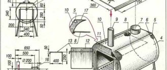
The ideal installation option is the Potapov heat generator, which has a rotating disk (1) installed opposite the stationary one (6). Cold water is supplied from the pipe located at the bottom (4) of the cavitation chamber (3), and the already heated water is discharged from the top point (5) of the same chamber. An example of such a device is shown in Figure 2 below:
Rice. 2: Potapov cavitation heat generator
But the device was not widely used due to the lack of practical justification for its operation.
Kinds
The main task of a cavitation heat generator is the formation of gas inclusions, and the quality of heating will depend on their quantity and intensity. In modern industry, there are several types of such heat generators, differing in the principle of producing bubbles in the liquid. The most common are three types:
- Rotary heat generators - the working element rotates due to an electric drive and produces fluid turbulence;
- Tubular - change pressure due to a system of pipes through which water moves;
- Ultrasonic - the heterogeneity of the liquid in such heat generators is created due to low-frequency sound vibrations.
In addition to the above types, there is laser cavitation, but this method has not yet found industrial implementation. Now let's look at each type in more detail.
Rotary heat generator
It consists of an electric motor, the shaft of which is connected to a rotor mechanism designed to create turbulence in the liquid. A special feature of the rotor design is the sealed stator, in which heating occurs. The stator itself has a cylindrical cavity inside - a vortex chamber in which the rotor rotates. The rotor of a cavitation heat generator is a cylinder with a set of depressions on the surface; when the cylinder rotates inside the stator, these depressions create heterogeneity in the water and cause cavitation processes to occur.
Rice. 3: Rotary type generator design
The number of recesses and their geometric parameters are determined depending on the model of the vortex heat generator. For optimal heating parameters, the distance between the rotor and stator is about 1.5 mm. This design is not the only one of its kind; over the long history of modernizations and improvements, the rotor-type working element has undergone a lot of transformations.
One of the first effective models of cavitation converters was the Griggs generator, which used a disk rotor with blind holes on the surface. One of the modern analogues of disk cavitation heat generators is shown in Figure 4 below:
Rice. 4: disk heat generator
Despite the simplicity of the design, rotary-type units are quite complex to use, as they require precise calibration, reliable seals and adherence to geometric parameters during operation, which makes their operation difficult. Such cavitation heat generators are characterized by a fairly low service life - 2 - 4 years due to cavitation erosion of the housing and parts. In addition, they create a fairly large noise load during operation of the rotating element. The advantages of this model include high productivity - 25% higher than that of classic heaters.
Tubular
A static heat generator has no rotating elements. The heating process in them occurs due to the movement of water through pipes that taper in length or due to the installation of Laval nozzles. Water is supplied to the working element by a hydrodynamic pump, which creates a mechanical force of the fluid in a narrowing space, and when it passes into a wider cavity, cavitation vortices occur.
Unlike the previous model, tubular heating equipment does not make much noise and does not wear out as quickly. During installation and operation, you do not need to worry about precise balancing, and if the heating elements are destroyed, their replacement and repair will cost much less than rotary models. The disadvantages of tubular heat generators include significantly lower productivity and bulky dimensions.
Ultrasonic
This type of device has a resonator chamber tuned to a certain frequency of sound vibrations. A quartz plate is installed at its input, which produces oscillations when electrical signals are supplied. The vibration of the plate creates a wave effect inside the liquid, which reaches the walls of the resonator chamber and is reflected. During the return movement, the waves encounter direct vibrations and create hydrodynamic cavitation.
Rice. 5: Operating principle of ultrasonic heat generator
Next, the bubbles are carried away by the water flow through the narrow inlet pipes of the thermal installation. When moving into a wide area, the bubbles collapse, releasing thermal energy. Ultrasonic cavitation generators also have good performance characteristics, since they do not have rotating elements.
Manufacturing of a hydrodynamic circuit
After we have decided on the design of the nozzle, we move on to the next stage: the manufacture of the hydrodynamic circuit. To do this, you must first sketch out a circuit diagram. We made it very simple by drawing a diagram on the floor with chalk (see Fig. 13)
Figure 13 – Diagram of the heat generator we assembled.
- Pressure gauge at the nozzle outlet (measures the pressure at the nozzle outlet).
- Thermometer (measures the temperature at the entrance to the system).
- Air bleed valve (Removes air lock from the system).
- Outlet pipe with tap.
- Thermometer sleeve.
- Entrance duct with tap.
- Sleeve for thermometer at the inlet.
- Pressure gauge at the nozzle inlet (measures the pressure at the inlet to the system).
Now I will describe the circuit design. It is a pipeline, the inlet of which is connected to the outlet pipe of the pump, and the outlet is connected to the inlet. A nozzle 9 is welded into this pipeline, pipes for connecting pressure gauges 8 (before and after the nozzle), sleeves for installing a thermometer 7.5 (we did not weld threads for the sleeves, but simply welded them), a fitting for the air vent valve 3 (we We used an ordinary Sharkran, fittings for the control valve and fittings for connecting the heating circuit.
In the diagram I drew, the water moves counterclockwise. Water is supplied to the circuit through the lower pipe (shark faucet with a red flywheel and check valve), and water is discharged from it through the upper pipe (shark faucet with a red flywheel). The pressure difference is regulated by a valve located between the inlet and outlet pipes. In the photo fig. 13 it is only shown in the diagram and does not lie next to its designation, because we have already screwed it onto the leads, having previously wound the seal (see Fig. 14).
Figure 14 – Blanks for assembling a hydrodynamic circuit.
To make the circuit, we took a DN 50 pipe, because... The pump connecting pipes have the same diameter. At the same time, we made the inlet and outlet pipes of the circuit, to which the heating circuit is connected, from a DN 20 pipe. You can see what we got in the end in Fig. 15.
Figure 15 – Assembled hydrodynamic circuit.
The photo shows a pump with a 1 kW motor. Subsequently, we replaced it with the 5.5 kW pump described above.
The view, of course, was not the most aesthetically pleasing, but we did not set ourselves such a task. Perhaps one of the readers will ask why the contour size is so large, because it can be made smaller? We intend to somewhat disperse the water due to the length of the pipe in front of the nozzle. If you search the Internet, you will probably find images and diagrams of the first models of heat generators. Almost all of them worked without nozzles. The effect of heating the liquid was achieved by accelerating it to fairly high speeds. For this purpose, small height cylinders with a stationary inlet and a coaxial outlet were used.
We did not use this method to accelerate water, but decided to make our design as simple as possible. Although we have thoughts on how to accelerate the fluid with this circuit design, more on that later.
In the photo, the pressure gauge in front of the nozzle and the adapter with a sleeve for the thermometer, which is mounted in front of the water meter, have not yet been screwed in (at that time it was not yet ready). All that remains is to install the missing elements and proceed to the next stage.
I think there is no point in talking about how to connect the pump motor and heating radiator. Although we did not approach the issue of connecting the electric motor in a completely standard way. Since at home a single-phase network is usually used, and industrial pumps are produced with a three-phase motor, we decided to use a frequency converter designed for a single-phase network. This also made it possible to increase the pump rotation speed above 3000 rpm. and then find the resonant rotation frequency of the pump.
To parameterize the frequency converter, we need a laptop with a COM port for parameterizing and controlling the frequency converter. The converter itself is installed in a control cabinet, where heating is provided for winter operating conditions and ventilation for summer operating conditions. To ventilate the cabinet we used a standard fan, and to heat the cabinet we use a 20 W heater.
The frequency converter allows you to adjust the pump frequency over a wide range, both below the main one and above the main one. The engine frequency can be increased no higher than 150%.
In our case, you can increase the engine speed to 4500 rpm.
You can briefly raise the frequency higher to 200%, but this leads to mechanical overload of the motor and increases the likelihood of its failure. In addition, the frequency converter protects the motor from overload and short circuit. Also, the frequency converter allows you to start the engine with a given acceleration time, which limits the acceleration of the pump blades during startup and limits the starting currents of the engine. The frequency converter is mounted in a wall cabinet (see Fig. 16).
Figure 16 – Frequency converter control cabinet.
All controls and indication elements are located on the front panel of the control cabinet. The system operating parameters are displayed on the front panel (on the MTM-RE-160 device).
The device has the ability to record readings from 6 different channels of analog signals throughout the day. In this case, we record the temperature readings at the system inlet, the temperature readings at the system outlet, and the pressure parameters at the system inlet and outlet.
The setting for the speed of the main pump is carried out using MTM-103 devices. Green and yellow buttons are used to start and stop the engines of the working pump of the heat generator and the circulation pump. We plan to use a circulation pump to reduce energy consumption. After all, when the water heats up to the set temperature, circulation is still necessary.
Figure 17—Front control panel of the heat generator.
When using a Micromaster 440 frequency converter, you can use a special Starter program to parameterize the converter by installing it on a laptop (see Fig. 18).
Figure 18 – Laptop with installed frequency converter control program.
First, the initial engine data written on the nameplate (a plate with the factory parameters of the engine attached to the engine stator) is entered into the program. Such data includes
- Rated Power R kW,
- Rated current I nom.,
- Cosine,
- Engine's type,
- Rated rotation speed N nom.
After this, auto-detection of the motor starts and the frequency converter itself determines the necessary motor parameters. After this, the pump is ready for operation.
Application
In industry and in everyday life, cavitation heat generators have found implementation in a wide variety of fields of activity. Depending on the tasks assigned, they are used for:
- Heating – inside the installations, mechanical energy is converted into thermal energy, due to which the heated liquid moves through the heating system. It should be noted that cavitation heat generators can heat not only industrial facilities, but also entire villages.
- Heating running water - a cavitation unit is capable of quickly heating liquid, due to which it can easily replace a gas or electric water heater.
- Mixing of liquid substances - due to rarefaction in the layers to obtain small cavities, such units make it possible to achieve the proper quality of mixing of liquids that do not naturally combine due to different densities.
Advantages and disadvantages
Compared to other heat generators, cavitation units have a number of advantages and disadvantages.
The advantages of such devices include:
- A much more efficient mechanism for generating thermal energy;
- Consumes significantly less resources than fuel generators;
- Can be used for heating both low-power and large consumers;
- Completely environmentally friendly - does not emit harmful substances into the environment during operation.
The disadvantages of cavitation heat generators include:
- Relatively large dimensions - electric and fuel models have much smaller dimensions, which is important when installed in an already used room;
- Great noise due to the operation of the water pump and the cavitation element itself, which makes it difficult to install in domestic premises;
- Ineffective ratio of power and performance for rooms with small square footage (up to 60 m2 it is more profitable to use a gas, liquid fuel or equivalent electrical power with a heating element).\
Rotary heat generator
What is a rotary heat generator? In essence, this is a slightly modified centrifugal pump. That is, there is a pump housing (which in this case is a stator) with inlet and outlet pipes, and a working chamber, inside of which there is a rotor that acts as an impeller. The main difference from a conventional pump is the rotor. There are a great many designs of vortex heat generator rotors, and of course we will not describe them all. The simplest of them is a disk, on the cylindrical surface of which many blind holes of a certain depth and diameter are drilled. These holes are called Griggs cells, named after the American inventor who was the first to test a rotary heat generator of this design. The number and dimensions of these cells are determined based on the size of the rotor disk and the rotational speed of the electric motor driving it into rotation. The stator (aka heat generator housing), as a rule, is made in the form of a hollow cylinder, i.e. a pipe plugged on both sides with flanges. In this case, the gap between the inner wall of the stator and the rotor is very small and amounts to 1...1.5 mm.
It is in the gap between the rotor and stator that the water is heated. This is facilitated by its friction on the surface of the stator and rotor, during the rapid rotation of the latter. And of course, cavitation processes and turbulence of water in the rotor cells play a significant role in heating water. The rotor rotation speed is usually 3000 rpm with a diameter of 300 mm. As the rotor diameter decreases, it is necessary to increase the rotation speed.
It is not difficult to guess that, despite its simplicity, such a design requires quite high manufacturing precision. And it is obvious that rotor balancing will be required. In addition, we have to solve the issue of sealing the rotor shaft. Naturally, sealing elements require regular replacement.
From the above it follows that the resource of such installations is not so great. In addition to everything else, the operation of rotary heat generators is accompanied by increased noise. Although they have 20-30% greater productivity in comparison with static heat generators. Rotary heat generators are even capable of producing steam. But is this an advantage for a short service life (compared to static models)?
DIY CTG
The simplest option for implementation at home is a tubular-type cavitation generator with one or more nozzles for heating water. Therefore, let’s look at an example of manufacturing just such a device; for this you will need:
- Pump – for heating, be sure to choose a heat pump that is not afraid of constant exposure to high temperatures. It should provide a working outlet pressure of 4 - 12 atm.
- 2 pressure gauges and sleeves for their installation - placed on both sides of the nozzle to measure the pressure at the inlet and outlet of the cavitation element.
- Thermometer for measuring the amount of heating of the coolant in the system.
- Valve for removing excess air from a cavitation heat generator. Installed at the highest point of the system.
- Nozzle - must have a bore diameter of 9 to 16 mm; making it smaller is not recommended, since cavitation can already occur in the pump, which will significantly reduce its service life. The shape of the nozzle can be cylindrical, conical or oval; from a practical point of view, any one will suit you.
- Pipes and connecting elements (heating radiators in their absence) are selected in accordance with the task at hand, but the simplest option is plastic pipes for soldering.
- Automatic switching on/off of the cavitation heat generator - as a rule, it is tied to the temperature regime, set to switch off at approximately 80ºC and switch on when it drops below 60ºC. But you can choose the operating mode of the cavitation heat generator yourself.
Rice.
6: diagram of a cavitation heat generator Before connecting all the elements, it is advisable to draw a diagram of their location on paper, walls or on the floor. The locations must be placed away from flammable elements or the latter must be removed at a safe distance from the heating system.
Assemble all the elements as shown in the diagram and check for leaks without turning on the generator. Then try the cavitation heat generator in operating mode; the normal increase in liquid temperature is considered to be 3-5ºC in one minute.
DIY heat generator (video)
A cavitation heater is quite an interesting and economical way to heat a room. It is easily accessible and can be created independently if desired. To do this, you need to purchase the necessary materials and do everything in accordance with the diagrams. And the effectiveness of the device will not take long to show itself.
For heating rooms or heating liquids, classic devices are often used - heating elements, combustion chambers, filaments, etc. But along with them, devices with a fundamentally different type of effect on the coolant are used. Such devices include a cavitation heat generator, the work of which is to form gas bubbles, due to which heat is released.