Home / Gas boilers
Back
Published: March 25, 2020
Reading time: 8 min
0
1017
The Bear boiler is produced by the Slovak company Protherm. There are about 100 different gas boilers of this modification on the Russian market.
The most popular is the Proterm Medved floor-standing gas boiler, operating in the “Winter-Summer” mode. A unique feature of the brand is the developed Protherm service network - more than one and a half thousand service centers located not only in the Czech Republic and Slovakia, but also in Russia and many CIS countries
- 1 Who is the manufacturer
- 2 Varieties of Bear boiler models
- 3 Distinctive features
- 4 Technical characteristics Bear 40 KLOM
- 5 Installation features
- 6 Reviews of Protherm Bear
- 7 Error and fault codes
- 8 Maintenance of the Proterm Medved boiler
Boiler protective functions
Page 12
- Image
- Text
10
the temperature of the heating system is set at a temperature that is capable of compensating for the heat losses of the heated building at the lowest calculated outside temperature for a given region.
Note:
PROTHERM offers as additional accessories several room regulators tested to work with this type of boiler. If regulators from other manufacturers are used, Protherm is not responsible for incorrect or unreliable operation of the equipment.
Operating the boiler in equithermal control mode
The coolant temperature in the boiler is regulated depending on changes in outside air temperature. Setting the equithermal dependence function is only possible with an external sensor connected, which is not part of the boiler delivery. The procedure for setting the angle of inclination and parallel shift of the equithermal curve on the graph is given on page 6 of this
manuals.
Warning:
The connection of the room regulator and the outdoor sensor can only be carried out by a specialist from a specialized organization certified by Protherm.
Note:
With all types of regulation, the priority is heating the water in the boiler, i.e. As soon as a signal is received from the boiler sensor, the boiler will automatically switch to the boiler water heating mode. After heating the water in the boiler to the required temperature, the boiler will automatically return to heating mode.
Boiler power setting
The boiler power is set at the factory to maximum. If necessary, you can set the heating power of the boiler in accordance with the required heating load. In the boiler water heating mode, the boiler always operates at maximum power. Warning:
Changes to the boiler settings can only be carried out by a specialist from a specialized organization certified by Protherm.
Boiler protective functions
Smooth power modulation
Occurs based on constant comparison of current parameters with parameters set by the user; This regulation is proportional, i.e. with a larger difference between the compared values, the boiler operates with greater power and vice versa.
Frost protection
When the water temperature in the heating system drops to 8°C, the boiler will turn on, regardless of the “Summer” mode being turned on, the requirements of the room regulator or the boiler heating mode being turned on.
Protecting the DHW boiler from freezing
When the water temperature in the boiler drops below 8°C, the boiler will turn on to heat the water in the boiler. This
The boiler function is activated even when the boiler heating mode is turned off.
Pump jam protection
Reduces the likelihood of pump jamming due to the deposition of suspended particles on its rotating elements when the boiler is stopped for a long time (more than 24 hours) by turning it on briefly (30 seconds).
Pump run-down
After the boiler is switched off from operation by a signal from the room regulator, the pump circulates water in the heating system for approximately 1 minute (only in heating mode).
Anticycling
The anti-cycling function in heating mode limits the number of boiler restarts to a temporary one.
Boiler PROTHERM KLOM 17. Setting.
Before the “advanced” version of the Protherm Klom 17 Bear boiler (aka Protherm “bear”) came out, there were no problems with connecting to multi-circuit heating systems. And here, with the release of version klom 17, the insanity of European economy and greed reached its climax!
The fact is that the boiler has only one adjustable heating circuit and boiler heating control. Naturally, to expand the circuits, you need to buy additional hardware and spend money on accredited specialists.
I note that the prices are not at all affordable, given that “Protherm” has always belonged to the budget category. At the same time, it is not at all a fact that these specialists will be able to do anything. In my case it cost 2700 per call. Two calls to different “specialists” led to nothing. The servicemen threw up their hands and said something like “well, such a boiler. This is how it works.”
The work of the Proterma service department is the topic of a separate article. Anyone who buys their products is considered waste material and is no longer of interest to the company. I hope this is the first step towards the ruin and departure of this company from our market or, nevertheless, to a turn to face the consumer of their products. The second is preferable, since more than one carload of these boilers was imported to Russia.
At 73 degrees the boiler turns off
Let me explain that to connect external control (controller), the boiler is only required to maintain the supply temperature within a given limit (for example, 71 +/- 2 degrees) - that’s all.
Switching on occurs at 48 degrees.
Up to this point, all the boilers that I have encountered in my life have handled this perfectly. This same boiler stubbornly maintained a “temperature pause” of as much as 25-32 degrees. Naturally, there could be no talk of any adjustment. the automation simply began to “go crazy”, and in principle it was not possible to heat the boiler in this mode.
In general, we had to take on the setup ourselves. The optimal option, from our point of view, is described below.
The instructions contain a table with customizable functions, access to which is not specified anywhere (+2700 rubles for the service center!).
Entering the “service menu” of the Protherm Klom 17 Bear boiler.
To enter the “service menu”, hold down the “MODE” button for about 10 seconds.
Entering the service menu Protherm klom 17 Bear
Release the “MODE” button when the characters “00” appear
Press “+” or “-” to the value “35” and press the “MODE” button
We have entered the "Service Menu"
Use the “+” or “-” buttons to select the value d.02. » "Maximum burner blocking time"
The default value is “20 minutes”. We set the minimum possible to “2” minutes.
After these manipulations, the “temperature range” becomes about 10 degrees. All the other settings available from the service menu did not lead to a decrease in the temperature range. This is hardly enough to regulate heating, but for hot water supply it is clearly not enough. You can, of course, raise the temperature to 85 degrees. and enjoy what you've done. But we decided to “finish off the enemy.”
Manipulations with the Protherm Klom 17 Bear boiler.
We buy a “original” boiler sensor (for 1200 rubles) and measure its parameters. The original temperature sensor is a 10 kOhm thermistor . At room temperature it shows 11 kOhm , at 60 degrees 1.6 kOhm .
Sensor resistance for Protherm klom 17 at 60 degrees.
- Trick the Protherm klom 17 boiler and install a resistor in the range of 2-10 kOhm into the panel contacts “5 and 6”. (this option is for those who like to experiment)
- Buy an “Original sensor” for the boiler and control the boiler through the boiler controller.
- Buy a 10 kOhm NTC thermistor and don’t bother. (This option is preferable because of the price. Approximate cost is 50 rubles versus 1200 for the original!)
In the first case, you will receive a non-adjustable boiler outlet temperature of 80 degrees (-/+ 2 degrees). I think you can select the output temperature in this mode by reducing the set DHW temperature and changing the value of the connected resistor. At the time of the experiment, I did not have any other resistors other than 10 kOhm. On the other hand, the set temperature of 80 degrees is slightly more than ideal for installing external controllers.
Sensor readings at room temperature
In the second and third, it is possible to regulate the boiler temperature only from the boiler. In this case, the supply line temperature jumps will reach the maximum. In other words, we get two modes: 1) heating and 2) DHW mode.
In the hot water preparation mode , the boiler is guided by the boiler sensor and maintains the hot water temperature specified in the settings (point D.20).
The algorithm is as follows: The heating pump (connected to terminal X19) is turned off and the storage pump loading pump (connected to terminal X11) is turned on. After the water has heated up, the boiler switches back to heating mode by turning off and turning on the corresponding pumps.
The heating mode is set on the boiler (see instructions)
In the version without an outside temperature sensor, the boiler will maintain the set flow temperature.
With the use of an outside temperature sensor, a couple of additional functions appear in the boiler.
- Setting the supply line depending on the outside temperature - equithermal mode. Read more here.
- Possibility of automatic transition to summer/winter mode. Range from 15 to 30 degrees. (paragraph D.45)
Service and care
Page 13
- Image
- Text
11
interval of at least 1 minute or a drop in coolant temperature by 8°C.
Note:
If the boiler was turned off by a command from the room regulator, this restriction does not apply.
overheat protection
The overheating protection function turns on the heating pump when exceeding
the value of the water temperature in the heating system set by the user or if the temperature of the coolant in the boiler exceeds 85°C. If the temperature of the coolant in the boiler exceeds 90°C (fault F3), the boiler will automatically turn off.
Starting the pump depending on the coolant temperature
The boiler control system allows you to set the start time of the heating pump depending on when the boiler reaches a certain temperature. This temperature can only be set by an employee of an authorized service center.
Chimney draft control system
The boiler is equipped with a chimney draft control system (SKTD). If there is insufficient draft in the chimney, the flue gas thermostat will work and the boiler will automatically turn off (the gas supply to the boiler will stop).
Power outages
If there is a power outage, the boiler will turn off. When the power supply is restored, the boiler
will automatically turn on without losing the set operating parameters.
If, after the power supply is restored, a fault message appears on the boiler display, unlock the boiler using the RESET button.
Note:
Blocking of the boiler can occur due to its overheating as a result of stopping the pump after a power outage.
The malfunction is eliminated by pressing the RESET button located on the boiler control panel. If the fault cannot be resolved in this way, you must contact an authorized service center.
Warning:
All specified protective functions are valid only if the connection to the electrical network is correct (correct connection of the phase, neutral and ground wires) and the main switch is in the switched position (position ON (I)).
Heating safety valve
The boiler is equipped with a 3 bar safety valve. The safety relief valve is activated if the operating pressure of the coolant in the heating system is exceeded and protects the boiler from hydraulic damage.
Provide a relief line to the safety relief valve in accordance with applicable codes and regulations.
It is strictly forbidden to service the safety valve by persons who are not employees of specialized service organizations! If the safety valve trips, you must turn off the boiler and contact a service organization.
Service and care
Boiler care by the user
If necessary, you can clean the front panel of the boiler without removing it. Cleaning is carried out after disconnecting the boiler from the electrical network (necessary
turn the power switch to the “off” position). If moisture gets on the front panel, restarting the boiler is possible only after it has completely dried. Blood pressure needs to be monitored periodically
Answers from specialists operating Protherm boilers
___________________________________________________________________________
- Malfunctions and errors of Protherm boilers
- Repair of wall-mounted boilers Proterm
- Adjustments of floor-standing gas boilers Proterm
Question: I recently noticed that the voltage stabilizer clicks, after which the boiler starts to work unstably, what could this be? Answer: This is not about the boiler. The stabilizer clicks because the relay is triggered when the voltage drops in the network and breaks the phase for a short time - it is because of the phase break that the boiler may behave unstably. Question: I have a Protherm KLZ 50 gas boiler with a turbocharger. A problem has arisen - a stain has appeared on the firebox, and it is gradually increasing all the time. They called local specialists and said that usually no one addressed such problems.
After a few more calls, a specialist (chief engineer) finally arrived and adjusted the gas supply to the boiler - after which the boiler began to work with modulation (that is, first at low speed and then at full speed). Before this, it was always turned on at full power and threshed without stopping in cold weather. This was during the heating season of 2013 and the stain stopped growing. This year the entire spot began to grow again. What to do? Answer: If the burner insulation is not damaged, the stain will not affect the safe operation of the equipment. Question: Maybe the boiler cycles frequently and consumes a lot of gas because the boiler power is too high? I have S=220m2, power=38 kW. I took this power with the prospect of heating the garage. If this is so, then what should I do to stabilize the operation of the boiler and gas consumption? Answer: Definitely. We need to reduce the power. Not to the minimum, but proportionally. Question: Tell me: I’m planning a Cheetah 25K boiler and BKN Proterm B100Z. Are additional three-way valves and pumps needed? Answer: The three-way valve and pump are already built into the boiler. All you need is a boiler sensor. Question: what does a two-stage burner mean in relation to the Grizzly 65 KLO: this is the notorious winter-summer mode (i.e. 1st stage - summer, second stage - winter) or the minimum (1st stage) and maximum (2nd stage) boiler operation, which is normal It is set to maximum at the factory, there is no official information on the website, nor in the manual. Answer: A 2-stage burner is an analogue of modulation, i.e. the boiler can operate at maximum power (2nd stage), maybe at a reduced one (1st stage) or turn off if there is no demand for heat at all. Moreover, both stages are adjustable. Question: if the house is well insulated, then perhaps a 30 kW boiler will also operate. What does it have to do with when it’s cold - one power is needed, when it’s warmer - another, the temperature changes by 10-15 degrees during the day, from 0 to -15, etc. What then? Provided that you cannot regulate any boiler yourself, but call a specialist. Explain how to behave with this boiler? Answer: if the house is well insulated, the likelihood of clocking is reduced. The house cools down more slowly, the coolant in the heating system also cools down less, the boiler sees this and does not operate at maximum power, but modulates only to maintain it.
Choose a boiler with maximum power that will cover the maximum heat demand of your home. There is no need to take a large supply (unless you plan to expand). Then the boiler will modulate, depending on the need - it gets warmer outside, the power decreases, colder - it increases. Question: A Protherm 30 KLOM floor-standing boiler has been installed. The heating project is still under development; combined heating is assumed: radiators and heated floors. According to the instructions for the boiler, the power of the circular pump must be connected not directly to the socket, but through the boiler terminals, so that the boiler can turn off the pump at low temperatures and, as I understand it, therefore prevent corrosion of the cast iron. But for heated floors, it is assumed to use a heated floor with a mixing unit and another circular pump. When the main heating pump is turned off, the underfloor heating pump can still circulate through the boiler if it is plugged directly into the socket. In this regard, 2 groups of questions: 1) It turns out that in order to preserve the boiler, it is necessary to hang both pumps on the boiler terminals? But in the instructions I did not find any explanations about this and the maximum power of the connected equipment. Is this possible, what is the maximum power and is it possible to see some link to a document that allows this? 2) In addition, ideally, I would like to connect the power to the heated floor pump through a thermostat installed in the room (turns on the 220V power when the temperature decreases and turns off when the temperature increases), to automate the regulation of the floor temperature. It turns out that this is basically impossible? Answer: You cannot connect two pumps to one terminal. Proterm does not have such a control scheme. To control the TP there is cascade automation. SD2000 has been discontinued. Question: I can’t find data on the pump power for this boiler, maybe you can help? For example, if we have one pump with a head of 4 meters, then it consumes 45 W, if it is 6 meters, then it consumes 80 W, if one pump is 8 meters, then it consumes 170 W. So why is it not possible to connect 2-3 pumps of 45-80 W each? What is the reason for this? Answer: This is due to the fact that the manufacturer provides for connecting only one pump to the terminals. Connecting 2 or more is at your own risk. Question: about connecting the B200S boiler to the Bear KLOM 30 gas floor-standing boiler. The manual for the B200S says: To ensure the operation of the boiler with the PROTHERM boiler, an electromechanical three-way separating valve with a built-in electrical switching contact of size DN is supplied separately?” (for use with wall-mounted boilers) or DN 1” (for use with floor-standing cast iron boilers). The manual for KLOM says: The boiler control system regulates the heating of the boiler using a pump and an NTC boiler sensor. Nothing is said about a three way valve. It is not entirely clear which scheme is preferable? Which electromechanical three-way isolation valve with built-in electrical changeover contact is meant? Where can I see its characteristics? The principle of controlling the circulation pump is not yet clear; does the boiler turn off the pump or change its performance? Answer: These are two possible schemes for connecting the boiler to KLOM - through a three-way and through pumps. In the first case, no pumps other than a circulation pump are needed, in the second - a three-way pump. Question: Proterm Skat - is it possible to operate it painlessly from a generator using a single-phase switching circuit? Answer: Models 6K and 9K can operate from a mains voltage of both ~380V and ~220V, others only from ~380V. Question: Is it correct to connect the floor-standing boiler Bear KLZ 30 through a hydraulic separator to separate heating circuits (conditionally 2 circuits, respectively tied to automatic temperature control). Another thing I ask is that in KLZ the heating circuit of the built-in boiler is already integrated and, logically, when the boiler pump is turned on, the boiler circuit pump will be turned off.
Accordingly, there is no circulation - the secondary circuits will work on themselves, that is, drive the cooled coolant until the boiler pump turns off and the boiler pump turns on. Or don’t bother and install KLOM 30 and connect the boiler to the hydraulic arrow as a third circuit? Who will advise what? Answer: Protherm does not have such recommended schemes, but it does not prohibit them. That is, they have the right to exist. This is a question of correctness. As for the schemes. I believe that you can do it both ways, there are two nuances: In the first scheme, if you forget to close the hot water tap, the heating system will cool down and freeze in cold weather. This will not happen in the second scheme. Boiler room dimensions. The second option requires more space. Question: I installed a Skat 21 kW electric boiler, while studying the Installation and Operation Instructions for the boiler I found information that there should be a minimum distance above the boiler to the ceiling - 800 mm. What is this connected with, why is there such a gap? I did not find such a requirement in the instructions for the gas boiler. Is this specific to an electric boiler? In fact, I get about 400 mm. Is this a big problem? Answer: 800 mm is required to replace the heating element, if you have 400 mm, then to replace the heating element you will have to remove the boiler, this will not affect the operation of the boiler. Question: We have a Panther 25 kTV boiler connected, a week ago a specialist started it up. I woke up in the morning, the message error f68 is on, there is no such error in the book, what should I do? I'm trying to reset the reset error, the boiler starts up to a temperature of 32 and gives an error. Answer: The problem is loss of flame. That is, either the boiler does not see the flame (see towards the ionization electrodes), or there really is no flame (see towards the gas - supply or gas valve). Question: Problem, I have a Protherm KLOM 50 with a turbo nozzle, it worked for 1.5 years, it won’t start. When turned on, the turbo nozzle starts, the display shows an indication of the current coolant temperature and the indicator flickers on the right in the corner and that’s it! What is this? Answer: The turbo manostat may be stuck. If there is abnormally low atmospheric pressure, reduce sensitivity. Question: For a house S=100 m2, which is better, a floor-mounted or a wall-mounted boiler? taking into account the connection of heated floors in two rooms S = 16 AND 18 M2 AND THREE water distribution points. My choice fell on Proterm, but I don’t know which one exactly, please tell me? Answer: The approximate power for your home is about 15 kW. The design organization will tell you more precisely. As for the models, the main difference between wall-mounted and floor-standing boilers is, of course, dimensions and installation capabilities. They have different options for compatibility with thermostats. Mounted ones have wider control capabilities. It is also important to decide whether it is a double-circuit boiler or a single-circuit boiler + boiler combination. Question: A Proterm KLOM 40 boiler and turbo nozzle have been installed. I have been operating the boiler since December 2013... I monitored the operation of the boiler on visits in the morning and evening. I moved into the house in March and noticed a peculiarity. from time to time the boiler accelerates to 85 degrees at a set temperature of 60 degrees. Moreover, when the boiler accelerates to 85 degrees, the lower right mark flashes on the screen and the circulation pump does not vibrate (I can determine the operation of the pump connected to the boiler by placing my hand on it, otherwise you won’t hear it). after heating the boiler to 85, the pump turns on and the boiler goes into normal mode... it cooled down to 55, heated up to 65. What could it be? Answer: the diode is blinking - the boiler is operating in the boiler water heating mode. Everything is in order - this is a program for protecting against bacteria in the boiler - short-term heating. Question: how to determine the frequency of short-term heating? I read that when the water in the boiler is drawn in one burst, the boiler gives a stop command to the heating pump and, as a priority, heats the water in the boiler (a 200-liter boiler) and after heating the water in the boiler to nominal, it turns on the pump again to the batteries and since the boiler is in the error does not go away, which means the boiler automation does not find any violations. There are only two buttons on the boiler, and how smart it turned out to be. Answer: This boiler does not have an antibacterial function in the boiler. This causes the boiler to heat up. Regardless of the water supply, when there is a request to heat water in the boiler, the boiler switches to heating the boiler at maximum power, which is why the temperature rises to 85. Heating is not active at this moment. As soon as heating of the boiler is completed, the boiler switches to heating. DHW is a priority. Question: What is the difference (other than power) between the Gepard 23 MTV and Panther 25 KTV boilers? The sellers said that there are more copper parts in the Panther (the Cheetah is a cheaper Panther). So I want to understand what the fundamental design differences are in order to decide whether it’s worth overpaying. What are their heat exchangers made of? When there is a temporary outage of gas and/or electricity, do both boilers start working automatically? Answer: Structurally, there are different expansion tanks of 5 and 7 liters. Plus there is a difference in the design of the front panel. They are partly right, since the Panther is more powerful and has a larger heat exchanger. But in general, they are the same. in the event of a power outage/on, the boilers will turn on, if gas is turned on, both are in error, turning on after resetting the error. Question: It is necessary to connect only BKN to the 30 KLOM floor stand. This boiler will only work to load the boiler. Accordingly, the entire system consists of a boiler, BKN, safety group, membrane tank and circulation pump. How to do it right? Just connect a temperature sensor and a boiler loading pump to the block or are there any nuances? Answer: It is necessary to switch the boiler to “summer mode” for heating, then it will only work for the boiler. There are no other nuances. Question: Tell me, the Protherm Cheetah Boiler is installed, at low burner power an error 28 or 29 appears. And it still does not maintain the set temperature (it does not turn off after reaching the set temperature). Where to look, what to turn? Answer: Your boiler probably has problems with the gas valve. Here I can only recommend an examination by a specialist. Question: They installed a Bear KLS 40 boiler for me. It started normally, no one lives in the house yet, but I left the boiler on. 2 days later I arrived, the boiler was stuck with error F1. I reset the error, it starts, but at different intervals it throws f1 again. Could this be due to insufficient ventilation?
Or dig towards electricity? The voltage seems to be stable, but in any case I will install a UPS. And the second question is which gsm module is best to install on my protherm to control the boiler via SMS? Is it possible to reset errors via SMS? The phasing is observed, the hot water boiler is not filled and not turned on. Answer: This error means that the automatic ignition is blocked and the gas supply through the gas valve is stopped, i.e. loss of flame. Such a blockage can occur in cases where, being in the open gas valve mode, the ignition automatic system does not receive a feedback signal about the presence of a flame from the ionization electrode.
This malfunction can also be caused by the activation of the emergency thermostat or combustion products thermostat. Low gas pressure at the inlet, incorrect electrical connection (phase and zero are reversed) can also cause loss of flame. If the fault cannot be resolved using the RESET button, contact your service organization. Regarding GSM, Proterm does not have such modules. Question: It turns out that the modulation should work and the boiler will maintain a stable temperature with a water flow of 3 l/min? We will observe in practice. Well, it is clear that if the heat exchanger is clogged, there will be no normal heat exchange and water flow. We are talking about how the new boiler should work and whether there are gas adjustments for the DHW, i.e., the ability to reduce the power of the DHW so that the boiler does not cycle at low pressure in the water supply. Answer: After switching on, the modulation should maintain a stable temperature. There are no gas adjustments for DHW. Automation itself regulates the operation of gas fittings. Question: The SO10045 sensor for connecting a boiler is a thermal resistance. The thermostat performs a similar function. Why is a sensor needed to connect the boiler and boiler? Answer: the principle of operation is similar, but when operating from a thermostat, the boiler does not receive information from the boiler about the water temperature, therefore it is not able to modulate the heating power, but only turns on at full power and turns off, which is not economical. Plus, when using SO10045, the current temperature in the boiler is displayed on the boiler - convenient and clear.
___________________________________________________________________________
___________________________________________________________________________
- Malfunctions of the AOGV-23 ZhMZ boiler
- Parameters and design of gas boilers AOGV and AKGV
- Boiler automation Baxi Luna-3 Comfort
- Installation and installation of the Baxi Slim boiler
- Adjustments and maintenance of the Beretta Chao boiler
- Determination of error codes and malfunctions of Rinnai boilers
- Errors and malfunctions of the Termet gas boiler
- The meaning of error codes and malfunctions of Vailant boilers
- Determination of malfunctions and errors of Visman boilers
- Questions about servicing Navien boilers
- Questions about malfunctions of Kiturami diesel boilers
- Junkers boilers - Experts answer user questions
- Experts answer questions about Electrolux boilers
- Answers from Nova boiler repair experts
- Questions about Hermann boiler service
- Answers from Daewoo boiler service technicians
- Questions about servicing Ferroli boilers
- Questions from users regarding the repair of electric boilers Evan
- What causes an AKGV gas boiler to light up and immediately go out?
- What is wrong with the Alpha Color boiler if it shows error code E01
- Why does the AOGV boiler light up and go out quickly?
- How to eliminate error E01 on the Baltgaz boiler
- What is the problem if Dani’s boiler lights up but immediately goes out?
- Why does a Danko boiler light up but quickly go out?
- The Demrad boiler has stopped holding pressure, what is the problem?
- Why did the Gaslux boiler start to get hot and make noise?
- What is the reason if the Keber gas boiler lights up but quickly goes out?
- How to eliminate error code 01 on the Kiturami boiler
- What causes a Conord boiler to light up but immediately go out?
- What is the reason if the Lemax boiler lights up and goes out quickly
- Why does a Mimax boiler light up but suddenly go out?
- Why does the Hearth boiler light up but immediately go out?
- Why does a Ross gas boiler light up but go out quickly?
- What is the problem if the Siberia boiler lights up and goes out suddenly?
- Why does the boiler Signal light up and suddenly go out?
- What can cause a Termet boiler to make noise and get hot?
- Why does the Termotechnik gas boiler light up but suddenly go out?
- How can you eliminate error E01 on a Thermon boiler?
- For this reason, the Electrolux double-circuit boiler began to hum and heat up
- For what reasons does a Ferroli gas boiler display an error code A01?
- For what reason does the Immergaz boiler not operate on hot water supply?
- Why does the Navien gas boiler constantly turn off when heating and then turn on immediately?
___________________________________________________________________________
___________________________________________________________________________
___________________________________________________________________________
- Heating boiler piping
- STS boilers
- KVT boilers for solid fuel
- Pellet boiler Peresvet
- Steel floor standing boiler Raton
- Solid fuel boiler Thermology
- Errors and malfunctions of the Termet gas boiler
- Termona boiler repair
- Boiler repair Nova
- Hermann boiler service
- Comparison of gas boilers Lemax Premium-20 and Danko-20s
___________________________________________________________________________
- Daewoo boiler maintenance
- Demrad boiler malfunctions
- Mora boiler malfunctions
- Westen boiler repair
- Malfunctions of Immergaz boilers
- Types of solid fuel boilers
- Models and design of combination boilers
- Liquid fuel and double-circuit boilers
- Cast iron boilers on coal
- Boilers with modeling burners
- Imported boilers for heating systems
Warranty terms
Page 14
- Image
- Text
12
coolant in the heating system, replenishing it if necessary. Top-up of the heating system is possible only after the boiler has cooled to a temperature below 40 °C (according to data from the temperature sensor installed in the boiler). Failure to comply with this requirement may result in cracks due to thermal stress in the boiler material. In the event of a gas leak, you must shut off the gas supply to the boiler and contact a service organization.
Legionella protection
To avoid the possibility of Legionella pneumophila or other types of bacteria forming in the boiler, it is recommended to maintain the hot water temperature at about 60 °C, or periodically increase the heating water temperature in the boiler to 70 °C.
Professional boiler care
Once a year, preferably before the start of the heating season, it is recommended to service the boiler. Servicing is performed by employees of a specialized service organization. This service is not required to honor the warranty. However, lack of maintenance may result in malfunctions that are not covered under warranty. First of all, it's about checking
functioning and condition of the burner, correct power settings, checking the tightness of the chimney connections, cleaning the boiler heat exchanger,
monitoring the hot water boiler and checking the condition of the magnesium anode. It is especially important to check the functionality
safety valve, emergency thermostat and combustion products thermostat. Similar control is carried out after performing service work on these elements.
It is recommended to monitor the condition of the magnesium anode after the first six months from the date of commissioning of the boiler. The service organization determines the date of the next maintenance depending on the degree of wear of the anode at the time of its first inspection.
If the degree of wear of the anode is 60%, it must be replaced with a new one. Failure of the boiler due to wear of the magnesium anode is not a warranty case.
Note:
Wear of the magnesium anode is related to its protective function, so replacement of the anode is not subject to warranty.
Warranty terms
The warranty for the gas boiler PROTHERM Medved 20 (30, 40, 50) KLZ is provided on the basis of the product passport, a correctly completed complaint report and other conditions listed in the “Operation Manual”, “Installation Manual” (chapters Introduction, Installation of the boiler and
product passport.
Distinctive features
The Bear floor heating boiler runs on gas fuel, depending on the modification: TLO, KLOM, PLO and KLZ, and has different design solutions for organizing the operation of the burner device, the smoke exhaust system and the movement of the coolant in the circuit.
The main differences between Protherm Bear floor-standing gas boilers:
- Modulation of thermal power, with adjustment of gas consumption and energy savings during transitional heating periods.
- Electric ignition of the boiler, with a closed combustion chamber, ensures 100% automation of the combustion process.
- Cast iron heat exchangers for the heating circuit increase the service life of the boiler by 5-8 years, compared to the steel and copper version
- High efficiency, up to the maximum achieved level of 92%, reduces the cost of generated thermal energy and the payback period of boiler equipment to 3-4 years.
- Affordable gas boiler repair due to a developed service network.
KLZ Category. . . . . . . . . . . . . . . . . . . . . . ….
Page 15
- Image
- Text
13
Bear
20 KLZ
Bear
30 KLZ
Category . . . . . . . . . . . . . . . . . . . . . . . . . . . . . . . . . . . . . . . . . . . . . II
2H3P
Execution
. . . . . . . . . . . . . . . . . . . . . . . . . . . . . . . . . . . . . . . . . B
11BS
Ignition. . . . . . . . . . . . . . . . . . . . . . . . . . . . . . . . . . . . . . . . . electronic fuel. . . . . . . . . . . . . . . . . . . . . . . . . . . . . . . . . . pr./compressed gas. . . . . . . . . . . pr./compressed gas Maximum heat load. [kW] . . . . . . . 18.5/18. . . . . . . . . . . . . 28.5 / 27 Minimum heat load. . [kW] . . . . . . . . 13/12. . . . . . . . . . . . . . 20 / 19 Maximum thermal output. [kW] . . . . . . . . 17/16. . . . . . . . . . . . . 26 / 24.5 Minimum thermal power. [kW] . . . . . . . 12.1/11. . . . . . . . . . . . . 18.2/17 efficiency. . . . . . . . . . . . . . . . . . . . . . . . . . . . . [%] . . . . 90 - 92 / 89 - 91 . . . . . . . 90 - 92 / 89 - 91
Gas pressure
Inlet pressure. . . . . . . . . . . . . . [mbar]. . . . . . . . .20 / 30 . . . . . . . . . . . . . . 20 / 30 Nozzle diameter. . . . . . . . . . . . . . . [mm] . . . . . . . .2.65/1.7. . . . . . . . . . . . 2.65 / 1.7 Max. gas pressure at the injectors [mbar]. . . . . . . 10.5 / 27. . . . . . . . . . . . . 12.5 / 27 Min. gas pressure at the injectors. [mbar]. . . . . . . . 5.5/13. . . . . . . . . . . . . . 5.5 / 13
Gas consumption
(Q max.) . . . . . . . . . . . . . . . . . . . . . . . . . . . . . 2.0 [m
3
/hour] / 1.6 [kg/hour] 3.0 [m
3
/hour] / 2.4 [kg/hour]
Heating
Max. working pressure. . . . . . . . . . [bar]. . . . . . . . . . . . . . . . . . . . .3 Min. working pressure . . . . . . . . . . . [bar]. . . . . . . . . . . . . . . . . . . . .1 Recommended operating pressure [bar] . . . . . . . . . . . . . . . . . . . 1 – 2 Temperature range . . . . . . . . . . . . . [°C] . . . . . . . . . . . . . . . . . . 45 – 85 Boiler volume. . . . . . . . . . . . . . . . . . . . . [l]. . . . . . . . . .9,1. . . . . . . . . . . . . . . . .11.6 Expansion tank. . . . . . . . . . . . . . [l]. . . . . . . . . . . . . . . . . . . . 10 Max. pressure in expansion tank [bar] . . . . . . . . . . . . . . . . . . . . 3.5
Hot water
Max.inlet pressure. . . . . . . . . . [bar]. . . . . . . . . . . . . . . . . . . . .6 Set temperature range [°C] . . . . . . . . . . . . . . . . . . 40 – 70 DHW boiler volume. . . . . . . . . . . . . . . [l]. . . . . . . . . . . . . . . . . . . . 90 Expansion tank. . . . . . . . . . . . . . [l]. . . . . . . . . . . . . . . . . . . . 3.9 DHW consumption
*
. . . . . . . . . . . . . . . . . . . .[l/min] . . . . . . . . . 16.5. . . . . . . . . . . . . . . . .18.0
Electrical parameters
Voltage . . . . . . . . . . . . . . . . . . . . [V/Hz]. . . . . . . . . . . . . . . . . . 230/50 Power consumption. . . . . . . . . . [W]. . . . . . . . . . . . . . . . . . . .130 Protection class . . . . . . . . . . . . . . . . . . . . . . . . . . . . . . . . . . . . . . . . . . IP 40 Current strength. . . . . . . . . . . . . . . . . . . . . . . . [A] . . . . . . . . . . . . . . . . . . . . 0.8
Method for removing combustion products
. . . . . . . . . . . . . . . . . . . . .into the chimney
Chimney diameter. . . . . . . . . . . . . . . [mm] . . . . . . . . . 130. . . . . . . . . . . . . . . . . 130 Temperature of combustion. . . . . . . . [°C] . . . . . . . . . . 88. . . . . . . . . . . . . . . . . .116 Specific consumption of combustion products [g/s]. . . . . . . . . 13.3. . . . . . . . . . . . . . . . 19.8 Minimum chimney draft. . . . . [Pa]. . . . . . . . . . . . . . . . . . . . .2 Noise level (1 m from the boiler, height 1.5 m) [dB]. . . . . . . . . . . . . . . . . . . up to 55 Dimensions - height / width / depth [mm]. . . . . . . . . . . . . . . 1385 / 505 / 730 Weight without water. . . . . . . . . . . . . . . . . . .[kg] . . . . . . . . . 140. . . . . . . . . . . . . . . . . 155 * —
according to EN 625 standard
Technical specifications
20 (30) KLZ
KLZ Category. . . . . . . . . . . . . . . . . . . . . . ….
Page 16
- Image
- Text
14
Bear
40 KLZ
Bear
50 KLZ
Category . . . . . . . . . . . . . . . . . . . . . . . . . . . . . . . . . . . . . . . . . . . . . II
2H3P
Execution
. . . . . . . . . . . . . . . . . . . . . . . . . . . . . . . . . . . . . . . . . B
11BS
Ignition. . . . . . . . . . . . . . . . . . . . . . . . . . . . . . . . . . . . . . . . . electronic fuel. . . . . . . . . . . . . . . . . . . . . . . . . . . . . . . . . . pr./compressed gas. . . . . . . . . . . pr./compressed gas Maximum heat load. [kW] . . . . . . .38.5 / 36.5 . . . . . . . . . . . . 49 / 47.5 Minimum heat load. . [kW] . . . . . . . 27 / 25.5. . . . . . . . . . . . . 36 / 32.8 Maximum thermal power. [kW] . . . . . . . . 35/33. . . . . . . . . . . . . 44 / 41.2 Minimum thermal power. [kW] . . . . . . . 24.5/23. . . . . . . . . . . . . 31.5/28 efficiency. . . . . . . . . . . . . . . . . . . . . . . . . . . . . [%] . . . . 90 - 92 / 89 - 91 . . . . . . . 90 - 92 / 89 - 91
Gas pressure
Inlet pressure. . . . . . . . . . . . . . [mbar]. . . . . . . . .20 / 30 . . . . . . . . . . . . . . 20 / 30 Nozzle diameter. . . . . . . . . . . . . . . [mm] . . . . . . . .2.65/1.7. . . . . . . . . . . . 2.65 / 1.7 Max. gas pressure at the injectors [mbar]. . . . . . . 12.5 / 27. . . . . . . . . . . . . 13 / 26.5 Min. gas pressure at the injectors. [mbar]. . . . . . . . 5.5/13. . . . . . . . . . . . . . 7/12.7
Gas consumption
(Q max.) . . . . . . . . . . . . . . . . . . . . . . . . . . . . . 4.1 [m
3
/hour] / 3.3 [kg/hour] 5.2 [m
3
/hour] / 3.8 [kg/hour]
Heating
Max. working pressure. . . . . . . . . . [bar]. . . . . . . . . . . . . . . . . . . . .3 Min. working pressure . . . . . . . . . . . [bar]. . . . . . . . . . . . . . . . . . . . .1 Recommended operating pressure [bar] . . . . . . . . . . . . . . . . . . . 1 – 2 Temperature range . . . . . . . . . . . . . [°C] . . . . . . . . . . . . . . . . . . 45 – 85 Boiler volume. . . . . . . . . . . . . . . . . . . . . [l]. . . . . . . . . 14.1. . . . . . . . . . . . . . . . . 16 Expansion tank. . . . . . . . . . . . . . [l]. . . . . . . . . . . . . . . . . . . . 10 Max. pressure in expansion tank [bar] . . . . . . . . . . . . . . . . . . 3.5
Hot water
Max inlet pressure. . . . . . . . . [bar]. . . . . . . . . . . . . . . . . . . . .6 Set temperature range [°C] . . . . . . . . . . . . . . . . . . 40 – 70 DHW boiler volume. . . . . . . . . . . . . . . [l]. . . . . . . . . . . . . . . . . . . . 90 Expansion tank. . . . . . . . . . . . . . [l]. . . . . . . . . . . . . . . . . . . . 3.9 DHW consumption
*
. . . . . . . . . . . . . . . . . . . .[l/min] . . . . . . . . . 18.5. . . . . . . . . . . . . . . . . 19
Electrical parameters
Voltage . . . . . . . . . . . . . . . . . . . . [V/Hz]. . . . . . . . . . . . . . . . . . 230/50 Power consumption. . . . . . . . . . [W]. . . . . . . . . . . . . . . . . . . .130 Protection class . . . . . . . . . . . . . . . . . . . . . . . . . . . . . . . . . . . . . . . . . . IP 40 Current strength. . . . . . . . . . . . . . . . . . . . . . . . [A] . . . . . . . . . . . . . . . . . . . . 0.5
Method for removing combustion products
. . . . . . . . . . . . . . . . . . . . .into the chimney
Chimney diameter. . . . . . . . . . . . . . . [mm] . . . . . . . . . 150. . . . . . . . . . . . . . . . . 180 Temperature of combustion. . . . . . . . [°C] . . . . . . . . . 131. . . . . . . . . . . . . . . . .115 Specific consumption of combustion products [g/s] . . . . . . . . . . 31. . . . . . . . . . . . . . . . . . 50 Minimum chimney draft. . . . . [Pa]. . . . . . . . . . . . . . . . . . . . .2 Noise level (1 m from the boiler, height 1.5 m) [dB]. . . . . . . . . . . . . . . . . . . up to 55 Dimensions - height / width / depth [mm]. . . . 1385 / 505 / 730. . . . . . . 1385 / 590 / 730 Weight without water. . . . . . . . . . . . . . . . . . . . .[kg] . . . . . . . . . 180. . . . . . . . . . . . . . . . . 205 * —
according to EN 625 standard
Technical specifications
40 (50) KLZ
Installation Guide, Introduction
Page 19
- Image
- Text
17
Installation must be carried out, based on the design, by a qualified specialist from a licensed specialized company, who is responsible for proper installation and compliance with existing rules, regulations and regulations.
When installing the boiler on a base made of flammable materials (for example, wood, PVC, etc.), the boiler must be mounted on a substrate made of non-combustible materials.
Warning:
During operation, the temperature of the boiler in the upper part (primarily on the sides and top panel) can exceed the ambient temperature by almost 50 °C. The minimum working space that must be left free near the boiler must be such that repair work and maintenance can be carried out freely and safely (it is recommended to leave a minimum of 300 mm on each side and a minimum of 600 mm in front of the boiler).
The method of removing combustion products for this boiler is into a chimney with a constant draft of 2 Pa. The size of the outlet for connecting the chimney varies depending on the boiler power:
— for boilers PROTHERM 20, 30 KLZ — Ø 130
mm,
— for boilers PROTHERM 40 KLZ — Ø 150
mm,
— for boilers PROTHERM 50 KLZ — Ø 180
mm.
Warning:
It is prohibited to place objects in the chimney that obstruct the passage of combustion products (for example, various types of heat exchangers for using residual heat). The chimney is not included in the scope of supply of the boiler.
The design of the chimney must comply with all standards and requirements established by laws and
The Protherm KLZ boiler is used as heat generators in autonomous water heating systems.
Warning:
Commissioning of the PROTHERM KLZ boiler can only be carried out by a specialist from a specialized organization certified by Protherm.
For installation of the boiler, its commissioning, warranty and post-warranty repairs, there is a network of authorized service centers.
The gas heating boiler is intended for installation inside buildings in residential or commercial premises, subject to mandatory compliance with the rules and regulations in force in the area for the placement of gas appliances, as well as the requirements for premises for their installation.
Water with a carbonate hardness of up to 3.0 mol/cubic meter should be used as a coolant in the heating system. (6.0 mEq\l, 16.8 dH), colorless, clean, without sediment. With harder water, the water hardness should be reduced to avoid scale formation.
When installing boilers, you should be guided by the SNiP, Safety Rules in the gas industry, current in the given area, PUE, PTE\PTB of electrical installations of consumers, other norms and regulations in force in the given area, as well as local regulations of gas and electricity supply organizations.
Malfunctions caused by scale or dirt deposits in the boiler or heating system itself are not covered by the warranty.
Coordination of the choice of installation site, as well as the organization of supply and exhaust ventilation, is carried out in the manner established for the given area in accordance with the regulatory documents in force for the given area.
Installation Guide
Installation Guide
Introduction
Schemes and stages of connecting a wall-mounted boiler
Installation of gas equipment must be carried out by a specialist. However, the connection diagram for a Protherm wall-mounted gas boiler should be accessible and understandable to the average user. Since the “Panther” series is the most popular due to the fast heating of water using Aquafast technology and the ability to install equipment in a room without a chimney, let’s look at the intricacies of connecting boilers using the KTV series as an example.
Stage #1 - familiarization with the installation diagram
The first step is to carefully consider the design features of the model and the installation diagram. All this information is in the user manual supplied with the equipment.
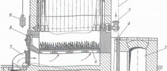
The structure of the equipment itself is shown in the diagram below.
A detailed diagram of the Proterm wall-mounted boiler is provided in each instruction manual from the manufacturer
Before direct installation, it is necessary to carefully consider the layout of all pipes.
The installation diagram is discussed below.
Such a boiler can become the center of an entire individual heating and water heating system, the approximate wiring of which is shown in this diagram
Stage #2 - hanging equipment on the wall
Once the package has been supplied and a safe installation location has been selected, a mounting template can be used to determine where to drill the holes.
But first you need to make sure that the selected wall can withstand the load and weight of the product, and the purchased fasteners can be used on a specific surface material.
The principle of hanging a gas boiler is shown in the diagram.
Proterm gas boilers are hung on the wall in the standard way, like other wall-mounted gas-using models
Stage #3 - installation work
Basic installation work takes place in several steps.
- The crimp threaded connection from the kit is installed on the gas pipeline.
- Then it is checked whether the volume of the built-in expansion tank is sufficient. If its capacity is insufficient, the structure should be equipped with an additional expansion tank, installing it on the return line of the heating system, as close as possible to the boiler.
- If there is a need to install an additional tank, a check valve should also be installed at the boiler outlet.
- All supply lines must be thoroughly flushed before installation.
- The cold water pipeline is equipped with a shut-off valve and a check valve.
After this, you can check the gas meter: this unit must be designed to pass the expected gas flow. If the meter meets the specified characteristics, you can connect the gas system to the supply or return line of the heating system. This process is clearly shown in the diagram.
Connecting the gas system to the boiler requires special care and compliance with all safety standards. These actions must be performed by a gas service representative with a special permit
The hot and cold water connections, as well as the hot water tank and drainage hose, are made according to the following standards.
Connecting hot and cold water is shown in the diagram in the instructions for the Protherm boiler (diagram 1). A visual connection of the drainage hose is shown in Figure 2
Next, connect the combustion product exhaust system. The KTV boiler, on the example of which we are considering the installation process, is equipped with a closed combustion chamber. The exhaust and intake of air in it occurs forcibly through a coaxial system, for which purpose the design includes a turbo chamber with a built-in fan.
The manufacturer offers several methods for installing a coaxial chimney, from which you can choose the most suitable option. The main thing is to ensure that the condensate flows outside the system or to specially installed condensate collectors.
Stage #4 - connecting the boiler to the power supply
The supply line for connecting the boiler must have a stabilizer and a circuit breaker.
Electrical installation of a gas boiler takes place in the usual way:
- The connecting wires are routed through the cable entry and shortened to an acceptable length.
- A corresponding plug is screwed onto the cable, freed from insulation and braiding.
- When all the wires are firmly inserted into the plug terminals, the plug itself is installed in the corresponding socket on the board.
- Finally, all cables must be secured with special clamps.
Any skilled craftsman can handle such manipulations. However, installation work carried out by a certified specialist is safer and meets the manufacturer's requirements.
documents that are relevant to this issue. Issue...
Page 20
- Image
- Text
18
documents that are relevant to this issue. By complying with the requirements listed in the standards, you can avoid such undesirable phenomena as excessive cooling of combustion products, penetration of moisture into the masonry, fluctuations in chimney draft, and, thereby, their negative impact on the operation of the boiler.
Combustion air enters the boiler from the room in which it is installed. It is necessary to ensure the flow of sufficient combustion air into the room - about 11 m
3
air at 1 m
3
natural gas.
The boiler is installed in a frost-free room near the chimney. The permissible ambient temperature for boiler operation is from +3C to +45C.
The combustion air supplied to the apparatus must be technically free from chemical substances, which may contain, for example, fluorine, chlorine or sulfur. Aerosols, paints, solvents, cleaning agents and adhesives contain substances of this kind that can cause corrosion during operation of the device under unfavorable conditions, including in the chimney system. The combustion air should not contain mechanical impurities, for example: construction dust, sand, etc.
To remove combustion products from PROTHERM 20, 30, 40, 50 KLZ boilers, you can use an additional device “PROTHERM PT 20 (30, 40, 50) SEMI-TURBO extension”, which provides forced removal of combustion products.
The device makes it possible to operate cast iron boilers in cases where it is not possible to use the normal removal of combustion products into the chimney. The extension is connected to the boiler outlet to connect the chimney. The exhaust of combustion products of the extension allows the use of elements of separate chimneys from the Protherm chimney catalog for wall-mounted boilers.
The maximum chimney length is 10 equivalent meters (1 equivalent meter = 1 meter straight section or one 90° elbow).
Warning:
When using the PROTHERM PT 20 (30, 40, 50) fan extension, the combustion products thermostat terminals must be bridged before putting the boiler into operation. The safety element for this method of operation is the air manostat, which is included in the delivery set of the PT 20 (30-50) chimney extension. Only a specialist from a specialized organization certified by Protherm can install the extension on the boiler and put it into operation.
When performing service work while the extension is connected to the electrical network (even when the power switch is turned off), you must follow the safety rules!
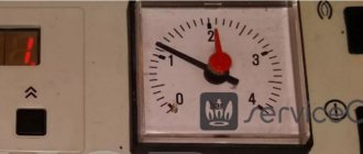
It is convenient to monitor the deviation from the initial water pressure in the heating system using the pressure gauge on the boiler control panel using the red arrow of the pressure gauge. If the pressure in the heating system drops, leaks should be found and eliminated, air should be released from the heating system, or the expansion tank should be checked.
The boiler expansion tank must be adjusted depending on the parameters of the heating system - in this way the heating system and all its elements are protected during operation from unwanted loads due to sudden changes in pressure.
When filling the built-in DHW boiler, it is necessary to open the cold water supply line to the boiler and the DHW outlet line from the boiler. As soon as water starts coming out of the DHW line, this will mean that the boiler is completely filled with water.
Note:
In front of the boiler (i.e. on
heating system return line), it is recommended to install a sedimentation tank for slag from the heating system. The sump can be combined with a sump tank; it must have shut-off service valves.
Comments
I need to fix the F5 error on the boiler, this is on page 9. and 10
Peter 02/17/2021 17:16 GMT
Select → I found the instructions for my water heater here! #manualza
- Click →
Instructions for the Chinese-made New Year's garland: - Use only indoors or outdoors.
Manualza!manualza.ru
Still not with us?
Installation features
Bear boilers are installed in a room protected from sub-zero temperatures, not far from the chimney. The permissible temperature of the internal air in the combustion chamber is from +5 C to +40 C.
The boiler is placed on a reinforced concrete foundation or on a concrete floor, which must support the full weight of the boiler filled with water and auxiliary equipment and not be slippery.
To remove boiler gases, it is allowed to install a fan and a smoke exhauster, which will ensure their forced movement. The size of the outlet pipe for connection to the chimney varies depending on the heating capacity of the model, for example, for KLZ 30 - 133 mm, and for KLZ 40 - 152 mm.
Before starting Proterm Bear for the first time, thoroughly wash the internal surfaces of the heating system. A safety relief valve is installed on the cold water supply line to the indirect heating boiler to protect against high pressure. It is prohibited to install any shut-off valves between it and the housing.
The unit must be equipped with a drainage line to drain water from the heating circuit during repair of the Proterm Medved boiler. Installation of the expansion tank is carried out by the safety group.
All main and auxiliary boiler equipment is tied according to the diagrams indicated by the boiler design and technical documentation of the manufacturer.