Conditions of work.
2.1. Insulation of the joints of polyurethane foam pipes begins after 100% inspection of the welds of the joints using a non-destructive method or after a hydraulic test of the pipeline.
2.2.. Work on insulating joints is carried out at an air temperature of at least -15 C°, as well as in the presence of technological pits of at least 1.4 m (0.7 m in each direction from the joint) and a depth of at least 400 mm, according to VSN 11-94 , VSN 29-95 and SP 41-105-2002
2.3. During precipitation (rain, snow), work is carried out only under temporary cover, which prevents moisture from entering the mounted elements.
2.4. When installing a heating main equipped with a system for online remote monitoring of the insulation condition (ODC), immediately before performing work on insulating the joint, it is necessary to connect the signal conductors and carry out control measurements in accordance with the “Instructions for connecting signal conductors” and “Instructions for carrying out control measurements”.
2.5. On pipelines with a steel pipe diameter of 273 mm and above, heat shrinkage of couplings is carried out using two gas burners simultaneously.
I. SCOPE OF APPLICATION
I. SCOPE OF APPLICATION
1.1. A standard technological map (hereinafter referred to as TTK) is a comprehensive organizational and technological document developed on the basis of methods of scientific organization of labor for performing a technological process and defining the composition of production operations using the most modern means of mechanization and methods of performing work using a specific technology. The TTK is intended for use in the development of the Work Performance Project (WPP) by construction departments and is its integral part in accordance with MDS 12-81.2007.
1.2. This technical specification provides instructions on the organization and technology of work on thermal insulation of external heating networks, defines the composition of production operations, requirements for quality control and acceptance of work, planned labor intensity of work, labor, production and material resources, measures for industrial safety and labor protection.
1.3. The regulatory framework for the development of technological maps is:
— standard drawings;
— building codes and regulations (SNiP, SN, SP);
— factory instructions and technical conditions (TU);
— standards and prices for construction and installation work (GESN-2001 ENiR);
— production standards for material consumption (NPRM);
— local progressive norms and prices, norms of labor costs, norms of consumption of material and technical resources.
1.4. The purpose of creating the TC is to describe solutions for the organization and technology of work on thermal insulation of external heating networks in order to ensure their high quality, as well as:
— reduction in the cost of work;
— reduction of construction duration;
— ensuring the safety of work performed;
— organizing rhythmic work;
— rational use of labor resources and machines;
— unification of technological solutions.
1.5. On the basis of the TTK, as part of the PPR (as mandatory components of the Work Project), Working Technological Maps (RTK) are being developed for the implementation of certain types of work on thermal insulation of external heating networks.
Manufacturing jobs.
3.1. Clean the ends of the thermal insulation, the surface of the polyethylene shell and the metal pipe from dirt so that the coupling can be moved on a clean surface. If necessary, rinse with water and dry with a gas burner. The polyethylene shell is cleaned to a distance sufficient to move the coupling over a clean surface, but not less than the length of the coupling used. Clean the steel pipe with a metal brush (cord brush) until loose layer rust is removed.
3.2. At the ends of the pipes, remove the layer of thermal insulation to a depth of 15-20 mm, connect the signal conductors and carry out control measurements in accordance with the “Instructions for connecting signal conductors” and “Instructions for carrying out control measurements”.
3.3. The P/E sheath, on both sides of the joint, at a distance of 150-200mm, should be degreased with solvent, thoroughly cleaned with sandpaper, and re-treated with solvent. When the ambient temperature is below 0°C, the shell must be heated at a distance of 30 cm on both sides of the joint so that it becomes hot to the touch (30°C-50°C).
3.4. Using a tape measure, center the position of the coupling relative to the axis of the joint, and mark with a marker the marks corresponding to the intended ends of the coupling. In this case, the previously prepared surfaces of the shells should extend 20-50 mm on both sides beyond the dimensions of the coupling. Do not use chalk for marking.
3.5. Unpack the coupling so that the outer surface of the packaging film is on the P/E shell of the pipe, but outside the area of previously prepared shell surfaces, and the coupling moves along the clean inner surface of the package. The inner surface of the coupling must be dry and clean. If the inner surface of the coupling is dirty, clean it from dirt, and the inner surfaces of the coupling to a depth
150mm from the ends must be degreased, cleaned with sandpaper and degreased again.
3.6. Drill a hole D=25mm on top of the coupling. at a distance of 150mm from one of the edges of the coupling.
3.7. Heat the prepared surfaces of the shells on both sides of the joint with a soft flame of a propane burner to a temperature of 30°C-50°C. Apply adhesive or mastic tape to the warm surface of the shells around the perimeter, departing 10-15mm from the marks. The overlap of adhesive or mastic at the joint is 10mm. Then remove the protective film from the adhesive tape or mastic. After removing the protective paper from the adhesive (or mastic) tape, dust, moisture, and dirt are not allowed to come into contact with its surface.
3.8. Push the coupling onto the joint, positioning it in accordance with the previously marked marks and the hole facing up.
3.9. Shrink the edges of the coupling. In order not to damage the coupling, it should be heated with a soft flame of a propane torch, using continuous circular movements evenly around the circumference of the coupling. Do not allow patchy shrinkage and overheating (P/E shine) of the coupling and shell. Upon completion of shrinkage, the edges of the coupling will tightly compress the shell. At the same time, the tight fit of the surfaces is controlled, without creasing or scuffing the edges of the coupling. After shrinkage, the coupling has a barrel-shaped shape.
3.10. Tightness control is carried out by crimping after the coupling has cooled to a temperature of 40°C.
A special device for crimping is inserted into the holes drilled according to clause 3.6, through which air is pumped into the coupling at a pressure of 0.4 bar. The coupling is maintained under test pressure for 5 minutes. In the event of a pressure drop, a soap solution is applied using a sprayer along the perimeter of the coupling-shell joints. Defective areas are identified by bubbles of soap solution. If defective areas are detected, reheat them with a soft flame of a propane burner and repeat the tests. If repeated crimping does not give a positive result, the coupling on the leakage side is sealed with additional adhesive (or mastic) tape and heat-shrinkable fabric. The tape is installed on the coupling-shell transition, so that the transition itself is in the middle of the tape. A heat-shrinkable fabric with a width of at least 200 mm is installed on top and heat-shrinked.
Galvanized insulation of polyurethane foam pipes and utilities - characteristics, installation
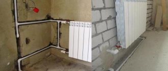
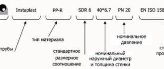
When installing heat-conducting pipelines for transporting hot liquids and steam in industrial and municipal areas, thermal insulation of pipelines from the external environment is always relevant. In the industrial sector, steel pipelines with thermal protection made of polyurethane foam insulation (PPU) are widely used, on the outside of which polyethylene or galvanized pipe insulation is used for protection.
Products with PPU insulation and outer coating are the main type of pipes with a ready-made protective sheath, manufactured at industrial enterprises. The regulatory act establishing the design of pipes and shaped elements (bends, tees, adapters), dimensional parameters, operating conditions of polyurethane pipes is GOST 30732-2006, which is used to guide the manufacture and installation of polyurethane foam lines.
In everyday life, galvanized insulation is used as shells - open cylindrical elements of various shapes, into which a thermal insulator for chimney pipes is placed.
Fig.1 Use of polyurethane foam pipes for heating and hot water supply
Designs for thermal insulation of fittings and flange connections
To insulate fittings and flange connections, depending on the material of thermal insulation of the pipeline, both cylinders and pierced mats made of mineral, basalt or glass wool or super-thin basalt fiber can be used. As a rule, slabs are not used to insulate reinforcement. For insulation of fittings and flange connections of pipelines, mats can be used in the form of mattresses covered with fiberglass, basalt or silica fabric on all sides. The type of fabric is determined by the temperature of the insulated surface. A removable metal casing is installed on top of the mattresses, the fastening of which can be carried out by locks welded directly to the casing, or by bandages with locks installed on top of the casing (Fig. 7 and 8).
Mattresses are attached to the insulated surface with bandages with buckles and tied with wire on hooks. Cylinders and stitched mats covered with metal mesh or fiberglass are used as a heat-insulating layer as part of fully prefabricated heat-insulating structures (cases or half-cases) for insulating fittings and flange connections of pipelines (Fig. 9).
In this case, the mats are installed in a case, pinned onto cotter pins or secured with glue. The case is equipped with bandages or locks. The cases are mounted on flange connections or flange fittings.
What is zinc pipe casing?
The use of polyurethane foam insulation on pipes is necessary to protect against two negative factors: the influence of the external environment and physical stress, leading to compression of the insulation and, accordingly, reducing its thermal insulation properties.
Also, the use of an outer shell is an important part of the technological process, in which a liquid polyurethane foam mixture is poured into the space between the inner steel pipe conducting the working environment and the outer one, forming a layer of insulation of the required thickness and shape.
The outer protective shell is made of polyethylene or steel, which is protected from corrosion by galvanizing.
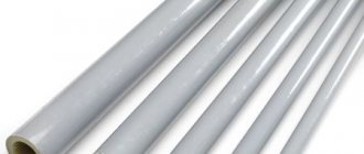
To produce external heat-insulating galvanized pipes, thin-walled steel up to 1 mm thick is used; during production, rolled pipe is dipped into a bath of hot zinc (hot galvanizing method) - thus obtaining a double-sided protective anti-corrosion shell. In production, zinc grades Ts0 and Ts1 are used according to GOST 3640-94; aluminum and lead are added to the bath (melted with zinc grade Ts2).
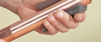
To increase strength, the outer pipe is produced with stiffening ribs; often a copper wire is built into the shell, which is necessary to monitor the integrity of the pipeline, the insulating coating and its outer shell.
Rice. 2 Rolled grades for the manufacture of PPU pipe coatings with galvanized steel
Polyurethane foam, from which the thermal protective shell is made, is found in everyday life in the form of foam rubber; it is used to make polyurethane foam, which is widely used in the construction industry. The component is obtained from a combination of two products of chemical oil refining - polyol and polyisocyanate; when a small amount of water is added to the mixture, carbon dioxide CO2 is formed, and its intense release causes foaming.
Thermal insulation with mineral wool
Of all the types of insulation available today, mineral wool is characterized by the lowest cost; the advantage is the ease of installation of insulation. Thermal insulation of pipelines with mineral wool – process:
- a roll of wool is cut into strips 200 mm thick (across) and they are then wrapped around the pipes, first with a layer of mineral wool (100 mm thick), on top with a tightly layer of fiberglass;
- Mineral wool should be laid evenly and should not wrinkle.
Mineral wool is considered as thermal insulation for pipelines of significant diameter; it is applicable for heating routes of urban networks and for sewerage systems; for sewer systems of small diameter and for water supply pipes - it is not practiced.
Thermal insulation of external pipelines
The choice of thermal insulation materials for external installation of heating pipes is quite large and are offered in the form of roll-type mats.
The pliability of the material allows them to be given a shaped shape for ease of installation; insulation materials are offered that are applied in liquid form, their further qualities appear after hardening.
Removable thermal insulation in a galvanized casing is widely used in linear sections of pipelines.
Foam rubber in the form of tubes or rolls, depending on the diameter of the pipes, is used as thermal insulation of pipes and parts of process pipelines; it is installed in several layers, depending on the required thickness of thermal insulation.
An interesting method for thermal insulation is a cover layer, the types of which can be found on the website:
Thermal insulation materials used on pipelines laid in the open air and directly on the surface of the earth will allow hot water not to cool down on the way to the consumer, and all types of pipes are insulated:
- plastic;
- metal;
- polymer;
- metal-plastic;
- composite.
Moreover, when independently thermally insulating communications in a private house, it is easier to work with pre-insulated pipes and self-adhesive insulation, and it is recommended to use additional winding, for example, aluminum tape, as an assistant to eliminate shortcomings.
Calculation of heat loss. The methodology for calculating possible heat losses by a pipeline, taking into account the actual temperatures of the coolant and air surrounding the system, the properties and thickness of thermal insulation, can be found here:
Thermal insulation materials for pipelines, including polyurethane foam and glass wool, are highly effective insulating materials in all their qualities.
Where is galvanized pipe insulation used?
The scope of application of galvanized polyurethane foam pipes for the transportation of liquid, gaseous and bulk materials is regulated by GOST 30732-2006, which establishes the following parameters of the transported medium:
- Working pressure in water and steam supply systems is no more than 16 bar. (atm.).
- The nominal temperature of the carrier is up to +140º C, the temperature of the passing liquid can be increased to +150º C if the heating network operates in the +70 – +150º C mode, established for external temperatures below -35º C in the European part of Russia, Siberia and the Far East .
PPU pipeline with galvanized insulation is a product intended for surface laying of thermal communications; when installed underground, it is pulled in the passages of channels and tunnels; its main areas of application are:
- Oil and gas industries. Pipelines with a polyurethane foam coating in the shell are used for the above-ground laying of oil and gas pipelines; in the climate of the Far North, insulation prevents excessive cooling of oil products and gas, which reduces their mobility.
Advantages and disadvantages of polyurethane foam pipes with galvanized insulation
Industrially produced pipes with PPU insulation have the following distinctive features and parameters:
- The technology for manufacturing polyurethane foam insulation consists of foaming the material; after it hardens, a fine-cell structure with a gas content of about 95% is formed. Due to this, polyurethane foam is lightweight and has low thermal conductivity. Of the entire class of foam plastics - products made from foamed synthetic materials, polyurethane foam has the lowest thermal conductivity of 0.02 W/m*K, which is 2 times lower than that of polystyrene foam.
- Polyurethane foam insulation is lightweight, with an average density of about 50 kg. per cubic meter, which is comparable to extruded polystyrene foam (Penoplex) and 2 times higher compared to polystyrene foam.
Rice. 5 Mechanical properties of galvanized steel
- PPU insulation does not absorb water, its water absorption does not exceed 1%, the material has low vapor permeability and excellent adhesion to all building materials.
- Polyurethane foam is afraid of ultraviolet radiation, therefore it is used in structures closed from daylight.
- The temperature range at which the material does not change its characteristics is -150 – +150º C.
- Polyurethane foam belongs to moderately flammable self-extinguishing materials, the burning duration of which is less than 30 seconds (flammability class G2), the temperature of the flue gases does not exceed 235º C.
- The service life of the protective layer of polyurethane foam is 30 – 50 years; the steel anti-corrosion coating of the pipe shell has a similar durability.
- Polyurethane foam is a chemically neutral component, does not interact with most aggressive chemicals, and decomposes when exposed to saturated acid solutions (nitric, sulfuric, hydrochloric).
- Polyurethane foam is environmentally friendly and does not emit harmful substances in its normal state.
- The material is highly resistant to biological influences (fungus, mold) and is not damaged by rodents.
- In the event of damage, repairs and insulation are carried out without dismantling the defective area, which distinguishes galvanized products from polyurethane foam with a polyethylene shell.
Rice. 6 Application of protective covers for galvanized steel pipes
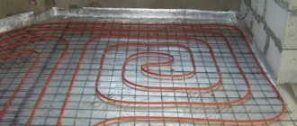
Installation of thermal insulation of pipelines
The Russian economy is one of the most energy-intensive in the world. According to IFC (International Finance Corporation) estimates, Russia could save 45%. This wastefulness is estimated at $84 billion to $112 billion in lost revenues from oil and gas exports. Meanwhile, resource extraction is falling, and the energy sector is no longer able to meet domestic demand: in a number of regions, there is a shortage of electricity during peak loads in winter. In June 2008, Dmitry Medvedev signed a Decree “On Certain Measures to Improve the Energy and Environmental Efficiency of the Russian Economy.”
The most deplorable state of affairs in our country has developed in the housing and communal services sector. ?Utilities infrastructure? is it a “black hole” where huge energy resources disappear without a trace? Losses in the heat supply system reach 60%?, ? noted Russian President Dmitry Medvedev.
When solving the problem of reducing heat loss, the main attention is usually paid to the thermal insulation of enclosing structures. However, more than half of the 60% of heat named by the president is lost not through the walls and roof, but through heating and hot water supply pipelines. Thus, by solving the problem of energy saving in utility networks, you can achieve double cost savings.
The higher the temperature of the coolant, the more important it becomes to use effective thermal insulation. If for hot water supply the temperature often does not exceed 60 degrees, then for district heating networks it already reaches 95, and in the main line leading to the central heating station from the thermal power plant it can reach 150 degrees.
The use of poor-quality or insufficient thermal insulation, especially in the last two cases, leads to the fact that a huge amount of heat and, accordingly, money is literally thrown into the air (or into the ground). The share of losses in heating networks now reaches 17% of the total thermal energy consumption in the country.
This state of affairs is due to two objective reasons. The first one? physical wear and tear of thermal insulation. According to estimates by the Ministry of Industry and Energy, on average in Russia there are 200 accidents per year for every hundred kilometers of communications. The wear and tear of heating networks in some regions sometimes reaches 75%. Much earlier than steel pipes and technological devices, traditional thermal insulation made of outdated glass wool according to GOST 10499-78 fails during above-ground and underground channel laying, as well as from reinforced foam concrete or bitumen perlite? for channelless installation. The average service life of these materials is only 10 years. At the same time, the intended service life of the pipelines is 25 years.
Being relatively hydrophilic, old materials absorb moisture and thereby further accelerate metal corrosion. Considerable additional expenses become inevitable: either for an unscheduled replacement of the heating main, or for the constant patching of individual sections with the simultaneous elimination of floods and fountains that have occurred.
The second reason is that the thermal insulation does not meet modern requirements. The coatings used for ductless installation are, by modern standards, more simply protective than thermal insulating. The thermal conductivity of reinforced foam concrete and bitumen perlite, even in a dry state, is about 0.1 W/m*deg., and with inevitable and rapid moistening it increases by another 3-5 times. At the same time, for efficient materials this figure does not exceed 0.05 W/m*deg.
Everyone is familiar with snowless and dry thawed paths, “indicating” in winter the heating main. Does glass wool produced according to Soviet GOST not meet the requirements not only for durability, but also for safety? especially for installers.
When using modern types of thermal insulation, another problem arises. It is too expensive to provide the required shell thickness with some materials. Therefore, despite the low thermal conductivity of the insulating layer, heat loss remains high.
Thermal insulation of pipelines is carried out not only to reduce heat losses, but also to reduce the surface temperature of the pipes for safe operation. In particular, in accordance with clause 2.1.8 of the “Rules for the construction and safe operation of steam and hot water pipelines?” (PB-10-573-03), “all pipeline elements with an outer wall surface temperature above 55 degrees, located in places accessible to operating personnel, must be covered with thermal insulation, the outer surface temperature of which should not exceed 55 degrees.” Therefore, the calculation of the thickness of thermal insulation when laying indoors can be made both according to the heat flux density standards and according to the specified temperature on the insulation surface.
It is clear that in the latter case, thermal insulation performs both functions, but in practice the thickness calculated from the surface temperature does not provide the necessary energy-saving characteristics.
Unfortunately, focusing on a safe surface temperature often turns out to be more attractive, since it allows you to get by with a thinner layer of thermal insulation and thus “save” money. facilities. In addition, many popular types of modern insulation are simply not manufactured in sufficient thickness. For example, products made from foamed polymers (polyethylene, synthetic rubber) are produced with a thickness of no more than 13-25 mm? Features of the technology make the production of products of greater thickness unreasonably expensive. Such thermal insulation does an excellent job of ensuring a safe surface temperature, but does not meet modern concepts of energy efficiency.
When setting the task of energy saving, thermal insulation should be calculated according to the heat flow density standards regulated by SNiP 41-03-2003. The required thickness of thermal insulation is determined according to the formulas presented in SP 41-103-2000. As an example, we can consider a heating pipeline with a diameter of 42 mm, with a coolant temperature of 90 degrees, passing in a room with an air temperature of 10 degrees, operating over 5000 hours per year. Let us take the thermal conductivity of the insulation as 0.04 W/m*deg, which approximately corresponds to the value of this parameter for modern materials (polymer and fiber) at elevated temperatures. The result of this approximate calculation shows that the minimum thermal insulation thickness in this case is 38 mm.
Required thickness? from 30 mm? have products made of mineral wool. Their use makes it possible to ensure that heat losses comply with modern energy efficiency requirements. Cylinders? the most convenient form of product for installation on pipelines? Available in fairly large diameters. For example, stone wool is produced with an internal diameter of up to 273 mm.
However, the thermal insulation of the required thickness? is not yet a guarantee of energy efficiency. Common mistakes can lead to a significant increase in heat loss. Among them, we highlight two:
1) The use of thermal insulation without taking into account the installation seal of fibrous materials. SNiP 41-03-2003 states that the thickness of a heat-insulating product before installation on an insulated surface should be determined taking into account the compaction coefficient Kc. For a cylindrical surface the formula is used:
,
where δ1? thickness of the heat-insulating product before installation on the insulated surface (without compaction), m;
δ ? calculated thickness of the heat-insulating layer with sealing in the structure, m;
d? outer diameter of insulated equipment, pipeline, m;
Kc? compaction coefficient of thermal insulation products.
It is impossible not to mention one more mistake, which often occurs even when all design and technological rules are observed. When thermally insulating pipelines, the cheapest ones are selected from all acceptable materials? for the obvious purpose of saving money. But, as is usually the case, unjustified savings result in additional costs. In this case ? for installation. Real saving of resources not only during operation, but also during installation can be achieved by using the highest quality materials. For example, pierced mineral wool mats, produced by many enterprises, have thermal conductivity that reaches the limit value specified in GOST 21880-94? 0.044 W/m*deg. The indicator of 0.036 W/m*deg, which characterizes high-quality products, allows you to use products of smaller thickness and, accordingly, reduce installation costs.
You can clearly see all the savings from the comparison estimate. It provides data on the thermal insulation of a pipeline with an outer diameter of 273 mm, with a coolant temperature of 100 degrees, located in the open air, with more than 5000 operating hours per year. The heat flux density, according to SNiP 41-03-2003, should be no more than 57 W/m. Based on this, the required thickness of thermal insulation is calculated: basalt mats (lambda = 0.036 W/m*deg) ? 90 mm, stitched mats according to GOST 21880-94? 110 mm (due to greater thermal conductivity), fiberglass mats? 120 mm (due to larger mounting seal). Accordingly, the volume of thermal insulation per 100 meters of pipeline length is: 10.25, 13.22 and 14.80 m3, respectively. It can be seen that, thanks to a smaller volume of thermal insulation, costs are reduced for all positions of installation work (labor of workers and machinists, installation of bandage rings, vehicles), as well as steel consumption for the protective coating. As a result, despite the highest cost of basalt mats, the final costs of their use are the lowest.
Thus, energy saving in housing and communal services in general and in pipeline networks in particular is inextricably linked with the effective use of thermal insulation. Already at the design stage, it is necessary to provide for the thickness of the insulating layer to ensure compliance with heat flux density standards. Further, for fibrous heat-insulating materials, the compaction coefficient should be taken into account, and during installation it is imperative to use elements that prevent the load on the insulation from the side of the protective coating. Finally, only modern, high-quality and durable materials should be used, thanks to which costs are reduced not only for operation, but also for the construction of pipelines.
Galvanized pipe insulation - varieties
The following technology is used in the production of polyurethane foam pipes:
- The supporting steel pipe is dried and cleaned of dirt, scale and rusty deposits, and ring supports made of plastic are placed on it.
- A copper conductor is threaded through the holes of the supports along the entire length of the workpiece.
- The pipe is pushed onto centralizers into the zinc sheath.
- Plugs are inserted into the ends, the surface is heated and liquid polyurethane foam is poured into the interpipe space.
- After technical quality control and marking, the pipe is sent to a warehouse for storage.
Pipes with PPU thermal insulation are produced with a diameter of 32 to 1420 mm (GOST 30732-2006); their length for a pipe diameter up to 219 mm is in the range of 8 - 12 m, for diameters over 273 mm the length is 10 - 12 m.
To increase the service life of products, galvanized pipe insulation is additionally coated on the outside with paint, polymer and waterproofing compounds (bitumen primer), which are renewable during operation.
Rice. 7 Shaped connectors according to GOST 30732-2006
The length of the pipe coating should be equal to the polyurethane layer with a margin of 50 mm at the edges; the polyurethane ends of the pipes and fittings are covered with bitumen-rubber or other waterproofing. When supplying pipes up to 426 mm in size, they must have two diagonally arranged copper wires with a cross-sectional area of 1.5² mm; if the diameter exceeds 530 mm, three wires are used for 3, 9 and 12 o’clock.
Thermal insulation structures for industrial equipment
To insulate equipment, depending on its geometry, slabs of mineral, basalt or glass wool, or super-thin basalt fiber or pierced mats covered with fiberglass and metal mesh can be used. Canvases made of super-thin basalt fiber or unlined mats for insulating equipment should be used in exceptional cases, if no other material can be provided. The mats are recommended for insulation of horizontal and vertical equipment with an outer diameter of 530–1,420 mm. Boards for insulating equipment with a large radius of curvature and for flat surfaces. For horizontal and vertical devices with outer diameter from 530 to 1420 mm incl. (containers, heat exchangers, etc.) KVM-50 mats and other products with a corrugated structure can be used as a heat-insulating layer, since this does not require the use of supporting structures (on horizontal devices). Fastening the heat-insulating layer on horizontal devices with an outer diameter of 530 – 1420 mm can be provided with bandages and hangers similar to fastening pipelines (Fig. 10).
To insulate vertical devices with an outer diameter of up to 1,420 mm, the fastening of the thermal insulation layer is mainly provided on a wire frame using wire strings (Fig. 11).
It is recommended to make rings installed on the surface of the devices from wire with a diameter of 2–3 mm in increments of 500 or 600 mm, depending on the size and type of heat-insulating material used. Bundles of wire ties with a diameter of 1.2 mm are attached along the perimeter of the rings at a distance of 400 or 600 mm from each other when insulated with slabs and 500 mm when insulated with stitched mats. The number of ties is determined by the number of thermal insulation layers: 4 for single-layer insulation, 6 for double-layer insulation. After fixing the heat-insulating layer with screeds, it is planned to install bandages made of 0.7x20 mm tape. Three bands are installed when insulated with slabs and two bands are installed when insulated with mats 1,000 mm wide.
Installation of galvanized polyurethane foam protection
The installation of pipes is carried out by welding; to seal the joints, a polyurethane foam mixture is used, which is poured into the empty space using formwork made of galvanized sheets. To connect galvanized pipelines, a two-component polyurethane foam composition, a cover sleeve made from a segment of zinc shell and bitumen-rubber adhesive tape are used, the work is carried out in the following sequence:
- After checking and inspecting the quality of the weld, prepare a workplace to ensure free access for the worker to the joint, construct a temporary shelter from precipitation, the air temperature should not fall below -25º C.
- Clean, wash and dry the surface of the zinc shell, clean the pipe from dirt, paint, traces of scale and rust with a stiff brush until it has a metallic shine, degrease the inner surface of the casing and the galvanized shell in the contact area with solvent grade No. 646.
- Remove the waterproofing from the ends of the pipes to a depth of 15–20 mm; if it gets wet, remove the layer until a dry surface appears.
- The conductors of the operational remote control system (ORS) of adapters and pipes are connected or paired together.
- Cut out two strips of adhesive tapes with a pipe circumference length of 50 mm, heat the pipe ends with a gas burner to 80 - 90º C and glue the strips onto the surface, which melt slightly upon contact with the metal.
- In the same way, glue the strip to the longitudinal surface of the metal casing after heating the contact point with a gas burner.
- Install the protective casing on the surface of the pipes overlapping so that one edge goes from top to bottom, fix it at the edges with tightening belts.
- Using gas burners, the surface of the casing is heated along the edges and at the place of the longitudinal connection, gradually tightening the belts, the procedure is continued until the steel casing tightly fits the joints and extruded adhesion appears at the edges. To bleed air and fill, a hole with a diameter of about 10 mm is drilled in the upper part.
- Using a screwdriver and self-tapping screws, connect the edges of the casing along the entire length and circumference in increments of 100 - 250 mm, with a distance of 10 -15 mm departing from the edges.
Rice. 10 Galvanized pipe insulation example of installation at joints