Achievements of Russian railway technology
Greetings, our dear reader! Today we will have an unusual article, the topic of which is a diagram of the water supply system of a passenger carriage. For most of you, this information will be, so to speak, for general development, but we guarantee its accuracy and reliability, so it can also be useful to students.
The purpose of the water supply system, its main components
Water supply in passenger cars: diagram for car 61-4179
Sanitary equipment, which is the water supply system for carriages, helps to ensure the necessary conditions of hygiene and nutrition for people during long trips.
Each carriage is equipped with such systems, so passengers are provided with drinking water and water for other household needs. The system is periodically refueled when the train stops.
- Each carriage is equipped with heating and cooling devices. Water is supplied to the toilets, washbasins and dishwashers, which are located in the service area.
- The volume of the entire system in liters is 1200, based on the calculation that no more than 20 liters per day should be consumed per passenger, despite the fact that the system is replenished every 12 hours.
- The plumbing system is gravity-fed, which applies to both hot and cold water.
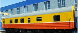
Passenger reserved seat carriage
Despite the fact that the cars often have different dimensions and structure, the water supply system in them is fundamentally no different.
Water supply for TV3 car
We will consider the water supply system for passenger cars using the example of a non-compartment car TV3.
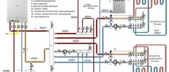
Above is a diagram in which we see:
- Small and large water storage tanks (66 and 86, respectively) - provide the system with cold water. They are spaced on different sides of the car for uniform distribution of liquid. To ensure pressure in the system, the tanks are located under the roof of the car.
- 96 and 99 are filling pipes and filling heads through which containers are filled.
- A network of pipes runs through the entire car , through which cold and hot water circulates.
- The system also contains trays (63, 85, 107) designed to collect condensate and water.
Water supply for passenger cars: boiler for heating water
- Sink (109), boiler (77) and device for cooling cooling water (103);
Car bathroom
- Water disinfectant , a tail pipe, fittings for releasing air from the system and many tap valves.
Now let's talk about all this equipment in more detail.
So:
- A large tank with a capacity of 850 liters is located behind the ceiling of the toilet and corridor at the non-boiler end of the car.
- A small tank with a capacity of 80 liters is above the toilet on the opposite side.
- Two welded pipes approach the body of the large tank, through which the system is filled. These pipes are equipped with shut-off valves to prevent water from splashing while the train is moving.
- There is also a pilot pipe located there, which serves as an overflow when refueling the system, that is, it prevents the tanks from overflowing.
Car water supply diagram: rear view
- The small tank is equipped with a pipe for air outlet, as well as a water meter glass, which allows you to control the level of filling of the tanks.
- Drain valves are installed on the tanks. The drainage occurs into trays through which the liquid goes under the car.
- The large tank is additionally equipped with a tap, which is also located behind the ceiling. It allows you to completely block the highway.
Filling the system
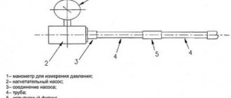
Cold water supply system for passenger cars: water is supplied to the system under a pressure of 10 atmospheres
The tanks are filled with water from the bottom of the car. The supply hoses are connected to the filling heads, which can be seen in the photo above.
Interesting to know! In winter, the heads can freeze, so they are preheated with hot water from the car's heating system.
- Pouring water into a cooled car at an ambient temperature below zero is carried out only after it has been kept in a closed heated room for 24 hours, or after starting the heating system of the car and warming up the air in it to +12 degrees.
- When filling the system, the following taps and valves must be opened: 61,91,69,83 - installed on the water connections to the toilets and washbasins; 68 – valve for air release; 64.65 – taps on water meter glass; 71 – valve for connecting to a hand pump; 78,79 – valves on pipes leading to the boiler; 80 – valve that turns off the main line; 3 – valve for filling the boiler; 140 and 141 valves installed on the filler pipes.
Train at the station
- Even before approaching the station where the system will be refueled, information is taken from the TEM (train electric mechanic) about whether the alarm system that monitors the end of filling is connected.
- If everything is functioning properly, the switch located on the control panel in the service compartment is switched to the “on” position.
- Filling of water will stop when the signal lamp, which is located next to the filling heads, lights up (only on cars equipped with an alarm), or when water appears from the leading pipe and the second filling pipe.
- To prevent water from spilling onto the railway track, a locking device 139 is used. On the side of the filling pipe, the leakage is controlled by filling valves.
Operating trains in winter always presents unforeseen difficulties
In cases of icing of the filling heads or failure of the heater, the system can be filled through a spare filling head (117). It is located in the boiler room near the reserve tank, which means it cannot freeze. With this filling method, an inventory hose is used, which is about 4 meters long.
If such refueling is carried out, the following measures are taken:
- The reserve head valve (70) closes;
- The inventory hose, one side is connected to the reserve head, and the other is led outside through the door and connected to the hose from the water stand located on the tracks.
- Afterwards, it is necessary to open the shut-off valve 70, and the water supply begins, during which you need to ensure that there are no leaks at the junction of the hose with the head.
- As soon as the large tank is completely filled, valve 70 closes, after which the flow of water through the column stops. The hose is disconnected and valve 68 is opened.
The position of the remaining taps and valves is similar to filling through the main filling pipes.
Draining
The cold water supply system of a carriage in a simplified form
To completely drain the water from the system, it is necessary to open all valves and taps. Its instruction manual explains how to drain liquid from a boiler.
- If it is necessary to empty the tanks, hoses are connected to them, which are stretched to the toilets, through which the flush occurs.
- For partial drainage of water, the following are used: mixer (75), toilets (95 and 114), taps (97 and 111).
- If the heating boiler stops operating (at sub-zero temperatures), the water from the water supply system must be drained before draining the water from the heating system.
Passenger car water supply system
The invention relates to railway transport, namely to the design of water supply systems for passenger cars. The essence of the invention is that the passenger car is equipped with a water supply system, the filling pipelines of which are equipped with safety devices consisting of an electromagnetic valve and an excess pressure compensator made in the form of a small-diameter bypass pipeline. The water supply system is equipped with a tank fill level sensor, which transmits a command to close the valve of the electromagnetic safety device when the tank is maximally filled, and a pressure sensor to duplicate the command to close the electromagnetic valve at critical pressures in the water supply system. The overflow pipeline is mounted next to the heating system pipe riser and has a common insulation shell along the length of the riser.
The invention relates to railway transport, namely to the design of water supply systems for passenger cars.
There is a well-known water supply system for a passenger carriage developed by the Tver Carriage Works (Passenger carriage without compartment. Technical description and operating instructions. Kalinin. Regional typography 1988, Fig. 35, p. 49). The water supply system is equipped with two filling pipes with connecting heads with heating of the pipes of the lower part from the heating system. The filling pipes are not equipped with devices for automatically shutting off the water supply to the water supply system tank when it overflows.
In cases of untimely shutdown of station water dispensers and the tank overflowing with excess water, an overflow pipe is provided inside the tank through which water is drained under the car and the critical pressure inside the water supply system decreases.
However, at present, in order to reduce the time for refueling passenger trains, station water intake dispensers are equipped with powerful pumps that allow refueling under a pressure of 6 atm, which, if the station dispensers are untimely switched off, can lead to the destruction of components of the water supply system.
The disadvantages of the analogue also include:
— lack of devices for automatically shutting off the water supply to the tank when it overflows;
— large losses of drinking water drained under the car through overflow pipelines.
There is a well-known water supply system for serial passenger cars manufactured at the Tver carriage building city of Tver) equipped with a filling device U3-2-4 (operating manual MVYU. 667442.003 RE, approved by MVYU. 407729.001 RE-LU).
The water supply system of a passenger car contains filling pipelines with connecting heads and
overflow pipeline. The filling device contains electromechanical valves (left and right), a drive control unit and an indication board. The supply of drinking water to the tank of the water supply system of a passenger car when it overflows is shut off by a ball valve with manual and automatic drive from an electric motor.
The filling device is designed to automate the filling of the tank with water in the water supply system of a passenger car, and also monitors the filling of the tank with water and provides operational information to the operating personnel.
Electromechanical valves (right and left) switch from the open position to the closed position and back.
The drive control unit controls the drive of electromechanical valves and provides control over the filling of the tank level.
The complexity of the design of the electromechanical valve drive and the possibility of it jamming when small fractions in water get on the ball surface should be considered among the disadvantages of the analogue.
As the closest analogue of the invention, a water filling system for a passenger car is known, protected by the RF patent for invention No. 2250170 under application No. 2002125328 dated September 23, 2002.
The water supply system of a passenger car contains filling pipelines heated in the lower part of the car body, connecting heads and an overflow pipeline. It contains a receiving tank with a float valve fixed inside in a fixed casing and water distribution lines for the domestic needs of passengers. The filling line of the receiving tank is equipped with an automatic shut-off valve with a diaphragm drive of a rubber poppet valve.
The disadvantages of this filling system include the fragility of the rubber spool of the diaphragm drive, as well as the fact that when the shut-off valve is activated, the phenomenon of water hammer (sharp increase in pressure) occurs, which negatively affects the filling station equipment and can lead to rupture of hoses, damage to pipelines and injury to operating personnel .
The objective of the invention is to simplify the design of the water supply system of a passenger car and increase the reliability of its operation when performing refueling operations.
The essence of the invention is that the passenger car is equipped with a water supply system, the filling pipelines of which are equipped with safety devices consisting of an electromagnetic valve and a compensator
excess pressure made in the form of a small-diameter bypass pipeline. The water supply system is equipped with a tank fill level sensor, which transmits a command to close the valve of the electromagnetic safety device when the tank is maximally filled, and a pressure sensor to duplicate the command to close the electromagnetic valve at critical pressures in the water supply system. The overflow pipeline is mounted next to the heating system pipe riser and has a common insulation shell along the length of the riser.
The technical result achieved by the invention is to simplify the design, increase the reliability of the water supply and refueling systems of the passenger car, as well as ensure their operability during any period of operation.
The essence of the invention is illustrated by drawings, where:
Figure 1 shows a diagram of the water supply and heating system of the car with a safety device;
figure 2 is a cross-section of a passenger car with a tank and pipelines of the heating system and an overflow pipeline of the water supply system;
Fig. 3 is a cross-section of the heating system riser and the overflow pipeline of the water supply system in the insulating shell.
A passenger car with water supply and heating systems contains a heating boiler 1 (Fig. 1), a manifold 2 connected by supply pipelines 3 and 4 of the corridor and compartment sides of the heating network, risers 5 and 6 and return pipelines 7 and 8. Pipelines are connected to the supply tank 9 fillings 10 and 11, equipped with safety devices consisting of an electromagnetic valve 12, 13 and an excess pressure compensator 14 and 15, made in the form of a small-diameter bypass pipeline.
At the ends of the filling pipelines 10 and 11 there are connecting heads 16 and 17 with heating devices 18 and 19 located in the lower part of the car body connected to the heating network. The overflow pipeline 20 is installed next to the riser 5 of the heating network pipeline. The supply tank 9 is equipped with a tank fill level sensor 21, which transmits a command to close the valve of the electromagnetic 12, 13 safety device when the tank is maximally filled, and a pressure sensor 22 to duplicate the command to close the electromagnetic valve at critical pressures in the water supply system. The sensors are installed on pipeline 23 with shut-off valve 24, level sensor 21 is equipped with air pipeline 25. Overflow pipeline 20 is mounted next to riser 5 of the supply pipeline of the heating system. Overflow pipeline 20 and riser 5
The supply pipeline of the heating system has a common insulation shell 26 (Figures 2 and 3) along the height of the riser.
Refilling the water supply system of a passenger car with water is carried out as follows. Through one of the connecting heads 16 or 17, water from the station dispensers through filling pipelines 10 or 11 and open electromagnetic valves 12 or 13 is supplied to the supply tank 9. The filling of the tank is monitored by a level sensor 21. When the tank 9 is filled to its maximum, the level sensor 21 issues a command to closing the electromagnetic valves 12 or 13 - the water supply to the supply tank 9 is instantly shut off. When the water supply is suddenly cut off, the phenomenon of water hammer is smoothed out by the excess pressure compensator 14 or 15, made in the form of a removable pipeline of small diameter which continues to pass water into the tank from the station column and thereby reducing the amount of excess pressure from the station equipment. Replenishing the tank 9 with water through the excess pressure compensator 14 or 15 will not be able to create a large excess pressure inside the water supply system, because water will be drained in a timely manner through an overflow pipeline 20 of a much larger diameter than the filling pipeline, protecting the components of the water supply and refueling system from destruction.
For cases of failure of the level sensor 21, a pressure sensor 22 is introduced into the water supply system, which is designed to duplicate the command to close the electromagnetic valves 12 and 13 at critical pressures in the system, protecting the tanks from destruction.
In conditions of winter operation of passenger cars, the connecting heads 16 and 17 are heated by devices 18 and 19 connected to the heating system. For additional heating, the overflow pipeline 20 is mounted next to the riser 5 of the supply pipeline of the heating system and is enclosed with it in a common shell, where natural heat extraction occurs, eliminating the phenomenon of freezing of the pipeline.
1. A water supply system for a passenger car, containing filling pipelines heated in the lower part of the car body by devices connected to the heating system, connecting heads and an overflow pipeline, characterized in that the filling pipelines are equipped with safety devices consisting of an electromagnetic valve and an overpressure compensator made in the form of a small diameter bypass pipeline.
2. The water supply system for a passenger car according to claim 1, characterized in that the excess pressure compensator is made in the form of a removable pipeline.
3. The water supply system of a passenger car according to claim 1, characterized in that it is equipped with a tank fill level sensor, which transmits a command to close the valve of the electromagnetic safety device when the tank is filled to its maximum level.
4. The water supply system of a passenger car according to claim 1, characterized in that it is equipped with a pressure sensor to duplicate the command to close the electromagnetic valve at critical pressures in the water supply system.
5. The water supply system for a passenger car according to claim 1, characterized in that the overflow pipeline is mounted next to the riser of the supply pipeline of the heating system.
6. The water supply system for a passenger car according to claim 1, characterized in that the overflow pipeline and the heating system pipe riser have a common insulation shell along the height of the supply pipeline riser.
How does a hot water supply system work?
Diagrams of car water supply systems: drawing of a boiler installed in passenger cars
Hot water supply in compartment cars is a system consisting of a boiler (boiler) 144 installed in the boiler room and a pipeline through which water is supplied to water collection points.
- The boiler unit itself is intended not only for heating water, but also for cooking, therefore it is equipped with a stove and a spare tank.
- The system can operate in two modes (winter and summer). In winter, the water in the boiler is heated by water circulating in the heating system. It enters the coil from the boiler, and valves 47 and 6 open.
Boiler and his wonderful operator
- The stove is heated by solid fuel (wood, coal).
- In the warm season, when the boiler is turned off, the water is heated by the heat generated by burning fuel in the stove, and valves 47 and 6 are closed.
- When heated, water enters the boiler from the water supply system through taps 79, 78 and 105 (the latter is a three-way valve).
- The heated water is dispensed through tap 106.
- Through the tank 81 with boiled water, the liquid flows into the cooler, which is also equipped with a tank from which a drain valve (100) and an air release valve (102) lead.
- Cooled water is dispensed through a tap (104), which is installed in a niche in the corridor, on the boiler side.
Cold and hot water also flows to the wash bowls and sink. Cold water is also supplied to the toilets through valves 118 and 119.
Water supply for passenger cars
1. Introduction. Purpose of water supply in passenger cars
Water supply devices in passenger cars are designed to provide passengers with drinking water and to satisfy their domestic needs, as well as to replenish the heating system with water. Water supply devices in passenger cars include devices for boiling and cooling drinking water, for supplying hot water to wash bowls in toilets and sinks for washing dishes in service compartments. All passenger cars have a gravity water supply system.
The cars are refilled with water from a water stand at least 2 times a day. The volume of spare tanks is calculated based on the average rate of water consumption per passenger per day ≈ 20 liters. For passenger carriages, a 12-hour supply of water is considered optimal. The total volume of water in the cold water supply system for most cars is about 1000 liters. About 25% of the total volume of water is used to ensure uninterrupted operation of hot water supply.
2. Water filling pipes
The water filling pipe with a head is located on the non-working side of the car, under the body or on the side wall of the body, on both sides.
The backup filling head for the cold water supply system is located in the boiler room. The car is filled with water through it in cases where it is not possible to fill the car with water through the main water filling heads.
There are two types of water pipe heaters
1. Electrical
– for cars of later years of production.
Responsibilities of the conductor:
a) Turn on the toggle switch on the distribution board to heat the water-filling pipes for 10-40 minutes. before the train arrives at the station where water will be refilled.
b) Turn off the toggle switch after filling the car with water.
In the event of a malfunction of the electric heater, the water-filling pipes are heated with hot water using a heating pad with a hose.
2. From the heating system
– on cars currently produced, there are special devices in which water-filling pipes are placed. Hot water from the heating system constantly circulates in this device - the water-filling pipes are always warm and do not freeze in the cold season.
3. Installation of a cold water supply system
1. Large tank – capacity 850 liters, located between the roof and the ceiling at the non-working end of the car;
2. Small tank – capacity 80 liters, located between the roof and the ceiling at the working end of the car;
3. Pipe connecting the large and small tanks;
4. Valves located on the pipes near the tanks are designed to shut off the tanks in case of their malfunction;
5. A pipe runs from the tanks to the toilet; there is a valve on it to shut off the pipe in the event of a malfunction of the toilet shut-off device.
4. Toilet shut-off mechanism
1. Valve
2. Spring
3. Lever
4. Pedal
5. Counterweight
Sometimes water leaks through the toilet, the reason may be: a loose fit of the valve to the pipe; scale from the pipe getting under the valve; spring break; valve wear. Actions of the conductor: close the valve on the pipe to the toilet, close the toilet, report LNP and FEM.
5. Hot water system
Used in compartment cars. Comprises
: boiler installation; pipeline; cranes
The boiler unit is designed to heat water in the hot water supply system and for cooking. Comprises:
1. Ash pan with door;
2. Fireboxes with a door, a grate inside;
3. Cooking stoves with a door;
4. Smoke exhaust pipe;
5. Boiler, it has a coil.
The boiler unit operates in two modes:
a) During the heating season from the heating system
. In this case, hot water from the heating system enters the boiler coil, heating the water in it. The heated water is supplied through a pipeline to the taps of the wash basins of the toilets and the sink in the conductor's service compartment.
b) When the heating system does not work (the heating season is over)
– heating of water in the boiler is carried out by burning solid fuel (wood, coal).
Possible faults
The more devices there are, the more often repairs to the water supply system of passenger cars are required.
Malfunctions of the water supply system of a passenger car are not such a rare thing, and they occur mainly due to the constant vibration of the car while moving. The tightness of all connections is disrupted and, over time, cracks appear in the boiler, tanks, and pipes, despite the absence of strong pressure.
- In addition, rubbing parts such as valves, plugs and valves constantly wear out. There is no escape from corrosion either. As a result, leaks appear in different places in the system.
- Other malfunctions include: sticking of the toilet flush pedal, malfunction of shut-off valves, boiler, cooler, wash bowls and other things.
- All breakdowns are identified during car maintenance.
- Troubleshooting is carried out by special teams during scheduled repairs (depot and overhaul) and uncoupling repairs.
- Repair and maintenance are reduced to restoring the integrity of damaged parts and sealing joints.
During scheduled activities, the system is additionally flushed with drinking water.