Coolant temperature requirements
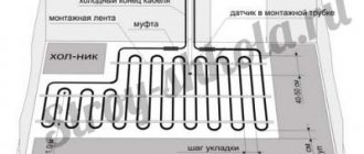
The heating system for underfloor heating is a rather complex set of equipment, the correct assembly and configuration of which largely determines the correct functioning of the entire heating installation. For example, if a boiler is designed to supply a coolant of 70-900C to the radiators, then in underfloor heating circuits operating in parallel in the same rooms, the temperature of the circulating fluid is allowed no higher than 45-500C (max 550C). The exact temperature parameters are derived through engineering calculations of the underfloor heating system. They are designed to ensure the treatment of water in the pumping system in such a way that the heating of floor surfaces, taking into account the structure and material of their coatings, does not exceed:
- in premises with long-term stay of people (offices, residential) – 290C;
- in auxiliary rooms (storage rooms, corridors, dressing rooms) – 300C;
- in bathrooms, bathrooms, swimming pools - 320C.
In addition, the setting of the mixing unit will be performed most optimally if it is possible to achieve a temperature difference between the supply and return of the TP of 5-150C. A decrease in the thermal gradient (Δt) requires an increase in coolant flow, as a consequence of an increase in its circulation rate, which leads to hydraulic losses. A high temperature gradient is already felt tactilely, like a difference in heating of the surface of the floor covering, which causes a certain discomfort.
Figure 2
Typical diagrams of pumping and mixing units
Depending on the method of switching on the circulation pump, the following NSU schemes are distinguished:
- sequential - fig. 2a;
- parallel - fig. 2b;
- combined.
In this case, the first two are considered the main ones, and the last scheme, accordingly, represents their hybrid version.
The pump connected in series is used only to prepare the coolant and circulate it in the heated floor circuits. Such a scheme, although it requires the use of two separate pumping units (for the primary and secondary circuits), however, is distinguished by better technological indicators than the parallel one. In professionally manufactured TP systems, the assembly of the pumping unit is often carried out with the sequential activation of the pump. It should be taken into account that the efficiency of such an assembly significantly depends on the correctness of its calculations and settings.
The advantage of connecting a pump in parallel is the ability to use just one unit to circulate the coolant in the primary and secondary circuits. On the one hand, this simplifies assembly, but on the other, it requires the installation of more powerful pumping equipment. If you make a mixing unit for a small household system yourself, then by choosing a parallel arrangement, it is easier to avoid critical mistakes that can negatively affect the operation of the water heated floor.
In both parallel and series LSU assemblies, the use of thermostatic two-way (Fig. 2-5 and 7) or three-way (Fig. 1, 8 and 9) valves is practiced. Schemes with thermostats of the first type are recommended for use in rooms with TP areas of several tens of square meters. Therefore, they are quite suitable for organizing underfloor heating in an average typical apartment. The coolant is mixed in them after a two-way valve directly in the circulation flow of the heated floor system.
Three-way thermostats are themselves mixing devices. Inside their housings there is a controlled admixture of coolant from the primary circuit to the circulating flow from the TP system. Three-way thermostatic shut-off and control valves are recommended for installation in large heated areas measuring hundreds of square meters.
Why use a mixing unit?
The most important difference between the operation of radiators and convectors and underfloor heating is the temperature of the working fluid.
So, for radiators, a water temperature of 60 to 90 degrees is used, which directly comes out of the boiler. But for a heated floor, the recommended liquid temperature is approximately 30-40 degrees.
The operating principle is similar to the operation of an ordinary mixer.
If we connect the circuits to the collector along with the batteries, then the warm floor will receive a large amount of heat, and this is not acceptable for a number of reasons.
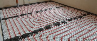
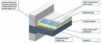
- Since the screed layer above the pipes is approximately 3-6 cm, high temperatures will lead to cracking and deformation of the layer.
- Pipes that are located inside the screed will experience greater load, which will lead to local stresses, since at high temperatures the linear expansion is much greater, and the pipes are limited by a layer of concrete screed. All this will lead to rapid failure of the pipes.
- Floor coverings do not like hot surfaces; they begin to delaminate and crack (laminate, parquet boards, parquet). In the case of ceramic tiles, peeling is possible. Linoleum loses its shape, dries out and becomes deformed.
- An overheated floor surface disrupts the microclimate of the premises.
- If we assume that the floor surface will warm up to 50 degrees, then it will be impossible to walk on it barefoot.
From the above it follows that the mixing unit is simply not replaceable. Since hanging a separate boiler on a “warm floor” system is simply stupid and not profitable.
And making minor changes to the heating system layout (if the heating is already installed) is not difficult. And if you are installing a circuit from scratch, then this device should be provided in advance.
It should be said that there are boilers on sale that immediately provide technology for heating and removing two liquid carriers of different temperatures at once. This equipment is very expensive and is not popular.
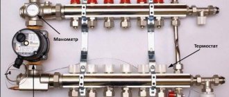
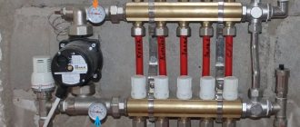
Design of the pumping and mixing unit
A pumping and mixing unit (PMU) is a complex device designed to constantly and stably maintain a given coolant temperature.
As well as uninterrupted coolant circulation in the system. If we use a combined heating method, then we must use a pumping and mixing unit for a heated floor.
The NSU should be considered together with the collector block. Since we said that this is a complex device, it therefore consists of several mechanisms.
Let's look at each one separately:
- The pump is designed to maintain constant circulation of the coolant. Due to it, the hot liquid and the cooled return liquid are mixed, after which it pushes the resulting composition through the system. It is advisable to use a circulation pump with switching operating modes.
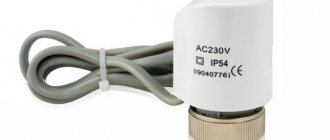
- The valve with thermostat is designed to control the temperature. There is a two-way valve; it is used when adjustment is not required. The three-way mixing valve is used for its stability and for large manifolds and long circuits. They can be of mixing and separation type, with a thermal head and a built-in sensor. It is recommended to use it with a remote sensor, they are more accurate. Recently, automatic valves that can be programmed have been widely used.
- Flow regulator. There are two types.
- First. The balancing valve has a scale from 1 to 10. These indicators depend on the length of the pipes. That is, while laying the contours, their length is measured and during adjustment the balancers are set according to the measurements. 10 corresponds to the longest length, and 1 to the shortest.
- Second. Float type, has a scale from 1 to 5. It looks like a transparent glass or flask. The numbers indicate consumption in liters per minute. A float (usually a single color) is placed inside the flask, which moves around the school depending on the pressure. The disadvantages include quick release due to scale.
- The collector block is used to connect several underfloor heating circuits. It is called a block because it combines a return collector and a supply. Collectors are designed for a certain number of connections.
These are the main components of the NCS, but the components and equipment can be varied. All components can be purchased separately and assembled a pumping and mixing unit for heating with your own hands.
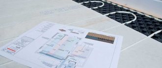
Homemade mixing unit for heated floors: design and assembly
Let's start by deciding on the materials that will be needed to make a homemade heated floor mixing unit. All of them can be bought separately at any construction market or store, or you can find an equivalent replacement for them, which will be much cheaper and, most importantly, will not affect the performance of the unit as a whole. Let us consider such a replacement and the manufacture of the mixing unit, or rather its parts, in more detail.
Collector. It can be made in two ways - twisted from tees with a diameter of ¾ inches or soldered from polypropylene tees of the same diameter.
In the latter case, it will cost more, since each of the branches of the comb will have to be equipped with a part such as an MRN, the cost of which is not so small. In any case, high-quality tees are a more suitable material - the main thing is to choose them correctly. In a situation with the manufacture of combs, tees with two outer and one inner ends are suitable.
They are twisted together using tow, without any additional fittings. How the mixing unit for a heated floor works photo Gidrostrelka. It can be made even without a three-way tap. It is quite possible to get by with the usual adjusting one, which is installed on heating radiators.
In addition to this, you will need two tees exactly the same as those used to make the combs, as well as a pair of connecting nipples with external and internal threads 50 mm long. Everything is assembled on tow - first, pipes (nipples) are screwed into both sides of the tap, and then one tee on each side is screwed to the nipples. Pump. Unfortunately, you won’t be able to make it yourself; you’ll have to purchase it at the store.
It is mounted in the lower part of the hydraulic arrow using detachable connections (American ones, which, as a rule, come complete with the pump). As an option, a pump can be installed instead of a hydraulic needle - you will get an excellent substitute that works no worse. At the same time, you will save on material. Heated floor contour: mixing unit photo Connect the hydraulic arrow with the combs.
Here it is also better to use detachable connections. If the pump is installed as a separate element (not instead of a hydraulic pump), then you will need to purchase an additional pipe, the length of which is equal to the length of the pump - it is installed on the supply, and the manifold is screwed to the pipe. So the option with a pump instead of a hydraulic arrow turns out to be more economical in all respects.
And then we equip the outlets of the combs with control taps, automatic air vents or, again, Mayevsky taps and, as they say, the matter is over - all that remains is to mount the mixing unit assembly for the heated floor in the proper place in a special cabinet and connect it to the heating system .
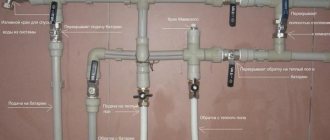
Everything is simple here - feed to feed, return to return. Naturally, the unit is connected through shut-off valves.
The heated floor is also connected to the mixing unit in the same way - one end of it to the upper comb, and the other to the lower comb. In order not to get confused later, you need to follow the layout - the return and supply of one segment of the heated floor must be connected under each other. You will also need to connect the power supply to the pump.
Basically, that's it. As you can see, assembling a mixing unit for a heated floor with your own hands is not very difficult.
The main thing is to understand the principle of its operation, study the device, and everything else, as they say, is a matter of technology.
Do you think otherwise? Then purchase a ready-made heated floor mixer assembly and spend additional money on its purchase. Alternatively, you can turn to friends who are competent in this matter.
Well, now it's time to finish the article. All the material I wanted to share has been reviewed. I hope it will be useful to you, and you will use it if you need to install a mixing unit for heated floors with your own hands. Improve your own practical skills and gain new knowledge, as they say: “It’s never too late to learn!” That's all, thank you for your attention, successful and easy repair!
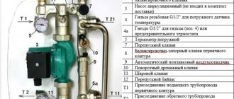
Equipment
The mixing unit is a complex mechanism, responsible for maintaining a stable water temperature and for its continuous circulation. It is included in the collector block and consists of a number of mechanisms.
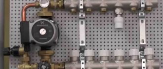
Pump
The main function of the pump is to create a constant movement of water through the pipeline. It supplies and returns it through the collector and floor branches. Its main indicators are pressure and productivity.
If calculated correctly, the pump will ensure that the hydraulic resistance in the floor line is overcome. It is recommended to use a device with an automatic operating mode switch.
Circulation pump
Flow regulator
Flow meters are:
- Primary circuit balancing valve (float) - it is responsible for the amount of coolant that enters the main line from the primary high-temperature source. The flow is regulated due to its throughput. The adjustment is made by a valve with a head; it is rotated with a key. Adjustment is also carried out by the thermostat valve, which is controlled by a remote sensor.
- Balancing valve of the secondary circuit - it is adjusted depending on the size of the heated area. By opening and closing the control valve, the proportions of the heated and cooled flow change. Closing the balancing valve of the secondary circuit return leads to an increase in the supply of hot coolant from the boiler, and this leads to an increase in thermal conductivity.
The degree of opening is adjusted using a scale printed on the flask. It determines the throughput of the device in m3 per hour.
Balancing valve
Bypass valve
The bypass, together with the bypass valve, helps ensure uninterrupted operation of the pumping equipment when the backpressure mode is in effect - when the circulation of liquid through the floor pipeline is completely or partially stopped. This can happen if the loop valves on the comb are closed manually or using taps.
As a result, the resistance to water flow increases, as well as the load on the mechanism. The pressure level in the system increases and the bypass valve opens.
The coolant flows through the bypass pipes and the pump, thereby closing a small circulation cycle. This leads to the elimination of emergency situations.
Bypass
Auxiliary elements
Auxiliary elements are also responsible for the functions of monitoring and maintaining the efficient operation of the pumping and mixing structure. This:
- thermometer - controls the temperature of the coolant;
- air vent - air is removed from the system through it;
Air vent
- drainage taps, their purpose is to drain water;
- check ball valve - prevents the flow of coolant in the opposite direction.
Collector block
Collector group - heated floor circuits are connected to it, calculated for a certain number of branches. It includes feed and return combs.
Examples of pumping and mixing units: operating principle
There are many schemes for mixing units, but we tried to select only the most understandable and easy to make with our own hands. All schemes are based on the same orientation - on the left side is the supply and return pipe supply, on the right side is the outlet to the underfloor heating manifold. Specifically, the collector itself can be connected to the pumping and mixing unit or located at a certain distance. This depends on the amount of space allocated for the equipment.
Example 1
A three-way thermal mixing valve must be installed in the pumping and mixing unit instead of the usual one. This device is controlled by a thermal head equipped with a remote sensor (its position remains the same).
The mixing of water flows occurs in a three-way valve. The valve works on the principle that when the stem changes its position, one passage begins to open slightly, and the other begins to close.
The three-way valve can be controlled not by a separate thermal head - many models are equipped with built-in temperature sensors. But some experts argue that a remote sensor is more correct and with it the system functions much better.
This example of connecting a unit assumes the use of a check valve installed on the bypass. It must be installed if the automation additionally “commands” the circulation pump. If you do not install a check valve, then when the circulation is idle, the bypass will turn into an ordinary uncontrolled jumper, and this will negatively affect the balance of the heating system and the operation of its other components. But if the pump operates constantly, this valve may not be installed, since it can become a source of additional hydraulic resistance.
Making a homemade collector
To make a manifold from polypropylene pipes, it is recommended to use structures with a diameter of 32 mm or 25 mm, corresponding tees and shut-off valves.
How many underfloor heating loops will be connected, how many tees and valves will be needed for the manifold. You will also need to purchase a circulation pump and valve for the mixing unit.
If the water heated floor system does not need serious automatic regulation, you can make the collector yourself or purchase a simple model with conventional shut-off valves
To solder pipes, you need a special soldering iron, as well as at least minimal experience in using such equipment. The supply and discharge sections of the collector are formed from tees and pipes. The pipe sections must be very short so that the tees are separated by very little space.
After this, stop valves are soldered, as well as fittings for connecting to the pump, etc. Such a simple device will not be expensive if you do not install flow meters and other control elements.
But a more advanced plastic collector is easier to buy than to make; the cost of such a device is low.
Features of the arrangement of mixing units
A do-it-yourself mixing group for underfloor heating, in which warm liquid is mixed with cold liquid, is installed next to the heater. If the hydraulic elements of the system are connected using elastic tubes, then the unit must be firmly fixed to the wall.
Before starting installation, you must make sure there is space for unobstructed access to the mixer parts. The control valve should be placed in the area where the coolant enters the heater.
When choosing a pipe material, you need to make sure that it can withstand the temperature of the incoming fluid. Experts recommend purchasing polymer pipe products. It should be remembered that galvanized pipes cannot be used for glycol-water solutions.
It is desirable that the shut-off elements be made of brass and bronze, the tubes made of black steel, and the pumping equipment made of cast iron. Steel products for the system from the outside are primed and painted at the factory.
When choosing the location and connection of the unit, you need to remember about air bubbles that may appear from the outlet of the boiler circuit. It is also necessary to exclude the possibility of water or condensation getting on the system elements that are under voltage.
Taking into account the above information, we can conclude that the mixing unit should be selected individually so as to ensure maximum ease of use of the floor surface heating structure. You can choose the connection diagram yourself or purchase a completely ready-made design.
Three-way valve for mixing unit. Its place and meaning
The main work in the operation of the pumping and mixing unit is played by a three-way valve or an automated analogue of the device, a three-way valve. Usually, mixing units equipped with similar devices are already on sale. If you decide to assemble the complex yourself, decide on the functionality of the valve and how it should work.
By default, valve models are configured for certain temperature parameters. If you wish, you can independently configure the device for your own heating system. To do this, simply move the thermal head of the valve to the desired position.
Important! Three-way valves have a low flow rate of only 2 m3 per hour. Therefore, it is optimal to use three-way valves for mixing the coolant when working with short-term water circuits. (For heating areas no more than 50m2).
To work with long-distance water circuits, three-way valves are used, designed for large volumes of water (up to 4 m3 per hour). As a rule, such devices have both a manual control option and are equipped with servo drives. Such devices are used successfully for the operation of heated floors in rooms with areas of more than 100 m2.
Do-it-yourself mixing unit for heated floors: purpose and design
If someone tells you that a heated floor mixing unit is just a distribution manifold that divides coolant flows into groups (so to speak, supplies it to different areas of the heated floor), you can safely accuse him of incompetence in this matter.
In fact, what they are talking about (distribution comb or manifold) is just part of the mixing unit, which also includes a lot of different equipment that serves not only to control the operation of the heated floor, but also to optimize this very work.
In general, this system is complex, and its structure should be understood in more detail - which is what we will do next. And let's start with the same manifold, which most novice plumbers confuse with a mixing unit for a heated floor.
A manifold or distribution comb - without it, the very existence of a pumping and mixing unit for a heated floor can be called into question. It is this element of the assembly that is fully responsible for the uniform distribution of coolant throughout all individual parts of the system.
Two such manifolds are installed in the mixing unit - one supplying and the second collecting, so the name “distribution comb” is in some way not entirely correct.
The distribution one is the one that is installed on the coolant supply to the heated floor, and the collecting one is the one that is mounted on the return pipeline.
Externally and structurally, they are similar to each other and represent a large-diameter tube, on the side of which there are threaded branches.
To make it more clear, I will say this - five, six or more tees of the same type and the same diameter twisted together. Here is your first hint on how to solve the problem of how to make a mixing unit for a heated floor circuit?
The hydraulic arrow, which, in fact, is the real mixer for a heated floor - it mixes the fresh coolant with the already “used” one, restores its temperature to its original value and again sends it to the distribution manifold, which, in turn, supplies it to each individual branch of the water-heated floor.
A hydraulic valve is installed at the very beginning of the mixing unit - it is a pipe connecting the supply and return of the heating system.
Exactly the same arrow is mounted after the boilers, in front of the distribution combs in the combustion chamber - naturally, the difference between them lies in the size and ability to drive a particular volume of coolant through itself. Three-way valve. Its purpose is to debug the process of mixing the coolant in the hydraulic arrow - it is installed at the bottom of the pipe connecting the supply and return. At the same time, it serves as a tee.
It is for this reason that, if we talk about the factory hydraulic arrow for heated floors, it is already manufactured complete with a three-way valve. By changing the position of this tap, we achieve efficient operation of the heated floor, and in particular, the effective reuse of the “waste” coolant.
Pump. You also can’t do without it - it’s what makes the coolant move quickly through all pipelines and effectively warm them up.
It is mounted on the return pipeline, between the hydraulic needle and the collecting manifold. By analogy, a thermal relay is installed on the supply, between the hydraulic needle and the distribution comb - it is only necessary if an automatic mixing unit is manufactured. If we talk about the manual control option, then you can completely abandon it.
Shut-off valves - installation of a mixing unit for a heated floor involves the use of two types of shut-off valves - these are ordinary ball valves, which are mounted before the mixing unit (their task is to cut off the entire unit from the heating system) and control valves, through which the system is debugged.
Automatic air vents - as a rule, are mounted at the end of the collectors. In the manual version, they can be replaced with conventional ball valves or Mayevsky valves.
This is what the diagram of a heated floor mixing unit looks like from the outside - at least its professional version.
If we talk about making such a unit with your own hands, then, naturally, it can be simplified to the maximum. We’ll talk further about how a homemade mixing unit for heated floors works and works.
Installation of pumping and mixing unit. Connection methods
When assembling a heated floor in your home, the hardest work is installing the screed. However, connecting water floors to a heating system is also not an easy task and requires certain knowledge. As a rule, the pump unit, mixer and manifold are installed after the installation of heating water circuits has been completed. Mixing stations are connected in a clear sequence. Each device and device must have its own place, which determines the functionality of the devices.
The equipment is installed in a manifold cabinet, in a heated room or next to it, in close proximity. All connections must be made in accordance with technology. For connection, a threaded connection, cold welding or coupling connections are used. When assembling the mixer and pump group with your own hands, try to achieve short and convenient connections that provide easy access to each structural element.
For connection and normal functionality of the unit, it is necessary to observe the correct arrangement of pipes and the settings of each element of the system:
- balancing valve (calculation of its installation location is required);
- circulation pump (feed speed adjustment required);
- balancing each branch of the heating circuit;
- bypass, three-way valve (requires adjustment in manual or automatic mode);
- carry out diagnostics of the finished unit, already fully assembled.
All connections must meet the requirements of thermal and hydraulic calculations. It is appropriate to recall here that before proceeding with the assembly and installation of the pumping and mixing unit, it is important to select the right equipment. Pump power, diameter and capacity of three-way valve. The number of water circuits plays a role in the selection of combs for the manifold group. Air vents and bleed valves must also be installed in certain places.
Author of the article Oleg Borisenko Similar posts
What you need to know about heated floors to make the right choice
Floor coverings for underfloor heating systems: linoleum and laminate
The main thing about thermostats - the control elements of underfloor heating systems Leave a comment Cancel reply
Name *
Email *
Comment Comments (2)
textarea>
Common Nodes
They differ in design, technical parameters, and functions. The main task is the implementation of floor heating. Methods for ensuring the operation of the system are different.
Valtec
The Valtec mixing junction maintains the specified temperature regime for the coolant in the secondary heating circuit. Possibly due to mixing from the return. The heating unit provides hydraulic coupling between a high-temperature heating system and a low-temperature heated floor.
In the operation of a water floor heating system, the unit is the main element. For a regular radiator, maintaining a temperature of 85 degrees Celsius is normal. For the floor - 35 degrees Celsius. Mixers ensure stability and uninterrupted operation of heating systems with low temperature conditions.
Valtec unit
Pumps are provided for constant circulation of water. Cooled liquid is continuously supplied from the return line to the coolant.
A special feature of Valtec mixers is related tasks for heating floors, gardens, and greenhouses.
TIM
The mixing connection of the series type displacement of the coolant TIM has a special feature. The full flow of the heating system is supplied to the consumer. Suitable for use in the heating system of a private home. You need to select the technical characteristics of the unit (model) and install it.
Unit mixing device TIM
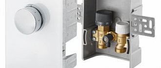
Oventrop
The Oventrop brand specialized in windows and doors. Over time, there was a respecialization into units for organizing heated floors in homes, and tools for installation.
Equipment:
- installation box;
- valve;
- valve for removing supply ventilation air masses;
- thermostat that controls the temperature of the coolant for the return line.
For laying water circuit pipes, it is customary to use mats - substrates with bosses. Material thickness - 11-35 mm. Installation of the circuit on a foil insulating ball is carried out using fixation bars and anchor brackets.
Oventrop mixing unit
A special feature of Oventrop pipes is the ease of installation of a heating system, mixing device, and connection to shut-off valves.
Watts
The Watts pump unit regulates the temperature in the range of 30-50 degrees Celsius. Possibly thanks to the TempGuard valve, Watts IsoTherm module.
Watts mixing device
Watts brand products are leaders in America and Canada.
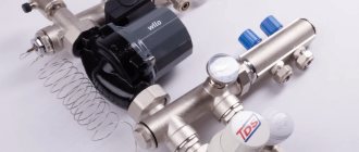
Wilo
Mixing pump units for Wilo underfloor heating are simple and reliable. The design is clearly thought out. It is possible to connect a collector for radiator heating.
Wilo mixing unit
The material can withstand temperatures of 90 degrees. Information is provided for the primary circuit of the heating system.
Which is better: Oventrop or Valtec?
The Valtec brand has a patent from Italy, but spare parts and elements of the floor heating system are produced in China to reduce costs.
Valtec devices are best used for heating large private and country houses. The manufacturer provides a 7-year warranty on the pipes. Shut-off valves break more often.
For apartment buildings with high pressure heating systems, it is better not to install Chinese pipes. There is a possibility of ruptures and leaks.
Oventrop is the best manufacturer of mixing units. The products are durable and reliable. Withstands changes in water pressure, ensures regular operation of the “warm floor” system.