What is a steam boiler?
A steam boiler is a unit for producing steam. In this case, the device can produce 2 types of steam: saturated and superheated. Saturated steam has a temperature of 100ºC and a pressure of 100 kPa. Superheated steam is distinguished by high temperature (up to 500ºC) and high pressure (more than 26 MPa).
Note: Saturated steam is used in heating private houses, superheated steam is used in industry and energy. It tolerates heat better, so the use of superheated steam increases the efficiency of the installation.
Where are steam boilers used:
- In a heating system, steam is an energy carrier.
- In the energy sector, industrial steam engines (steam generators) are used to generate electricity.
- In industry, superheated steam can be used to convert into mechanical motion and move vehicles.
Steam boilers: scope of application
Household steam devices are used as a heat source to heat a home. They heat a container of water and drive the resulting steam into the heating pipes. Often such a system is installed together with a stationary coal stove or boiler. Typically, household steam heating appliances produce only saturated, non-superheated steam.
For industrial applications, the steam is superheated. It is continued to be heated after evaporation to raise the temperature even further. Such installations require high-quality execution to prevent the steam tank from exploding.
Steam boiler
Superheated steam from the boiler can be used to generate electricity or mechanical movement. How does this happen? After evaporation, the steam enters the steam turbine. Here the steam flow rotates the shaft. This rotation is further converted into electricity. This is how electrical energy is obtained in the turbines of power plants - when the shaft of the turbomachines rotates, an electric current is generated.
In addition to the generation of electric current, shaft rotation can be transmitted directly to the engine and wheels. As a result, steam transport begins to move. A famous example of a steam engine is the steam locomotive. In it, when coal was burned, water was heated, saturated steam was formed, which rotated the engine shaft and wheels.
Operating principle of a steam boiler
The heat source for heating water in a steam boiler can be any type of energy: solar, geothermal, electric, heat from the combustion of solid fuel or gas. The resulting steam is a coolant; it transfers the heat of combustion of the fuel to the place of its use.
Various designs of steam boilers use a general scheme for heating water and converting it into steam:
- The water is purified and supplied to the tank using an electric pump. Typically, the reservoir is located at the top of the boiler.
- From the reservoir, water flows down through pipes into the collector.
- From the collector, water rises again through the heating zone (fuel combustion).
- Steam is formed inside the water pipe, which rises upward under the influence of the pressure difference between the liquid and gas.
- At the top, the steam passes through a separator. Here it is separated from the water, the remainder of which is returned to the tank. Then the steam enters the steam line.
- If this is not a simple steam boiler, but a steam generator, then its pipes pass through the combustion and heating zone a second time.
Design of the main elements of steam boilers
Content
- Combustion devices
- Steam-generating heating surfaces
- Steam boiler manifolds
- Superheaters
- Tail heating surfaces
- Steam boiler fittings
- Lining and insulation of steam boilers
- Frame, cladding, foundations and supports of steam boilers
Since the main type of boilers used as main and auxiliary boilers on ships with a boiler-turbine power plant (boiler-turbine power plant) are water-tube steam boilers with natural circulation, all subsequent material (unless otherwise stated) will be devoted to this type of steam boiler.
Combustion devices
Combustion devices for burning fuel oil consist of two main parts: a fuel nozzle designed for atomizing fuel, and an air guide device that ensures such organization of air supply that it is well mixed with atomized fuel, fuel is heated and evaporated, continuous ignition of the fuel-air mixture and stable its burning.
Combustion devices can be located on one or both fronts of the boiler, as well as on the side, top or bottom of the firebox. The number of combustion devices installed on the boiler can be from one (on auxiliary boilers) to 8 ÷ 16 (on main boilers). The lower the performance of each nozzle and the more of them are installed at the front of the boiler, the easier it is to achieve high quality mixture formation and combustion processes. But installing a large number of nozzles significantly complicates the design and operation of the boiler, the possibility of coking of idle nozzles increases and air leaks into the furnace through the gaps of idle VNU increases.
The following types of nozzles are used in ship steam boilers:
- mechanical - in injectors of this type, fuel is atomized due to the pressure created by the fuel pump. The fuel stream is pre-twisted in the vortex chamber and exits into the firebox in the form of a cone through a tangential hole. Mechanical injectors provide high atomization quality and are reliable, but have a small range of fuel consumption control. One type of mechanical nozzle is the rotary nozzle. In it, fuel is atomized due to the centrifugal forces of the rotating parts of the nozzle itself. But rotary nozzles are difficult to manufacture and less reliable in operation;
- air and steam (pneumatic) - these nozzles use the ejection effect, as a result of which a moving stream of air or steam carries fuel particles with it. The fuel flows to the nozzle by gravity from a supply tank installed above the nozzle, and under the influence of the kinetic energy of the steam or air jet, it is crushed into tiny droplets. Pneumatic nozzles have a simple design, are less demanding on the processing of parts, but to ensure high-quality atomization, their operation requires a large consumption of steam or air;
- steam-mechanical - combine the advantages of mechanical and steam nozzles. The nozzle tip has two channels: oil and steam. At high fuel flow rates, this nozzle operates like a conventional mechanical one, and at low flow rates, additional steam is supplied to ensure high-quality fuel atomization.
Air directing devices of steam boilers must have the following properties: ensure high quality and stability of torch combustion with minimum excess air ratios and the minimum possible hydraulic resistance of the boiler front; be able to regulate air flow rates in a wide range of boiler loads, while ensuring sufficiently high air flow rates at reduced load modes;
The following types of VDU (air guide device) are used in ship steam boilers:
- VNU with swirlers. In these devices, the air flow is swirled using a blade guide device - a swirler. The air passing through the blade apparatus of the swirler receives a rotational movement around the axis. Moreover, the air is swirled in the direction opposite to the swirl of the fuel jet in the nozzle in order to better crush the fuel and better mix it with air;
- axial VNU with stabilizers. In devices of this type, the aerodynamic conditions necessary for organizing a combustion source in a torch are created as a result of the interaction of an axial air stream with a conical stabilizer installed on the nozzle. When air moves behind the stabilizer cone, a rarefaction zone is created, causing a reverse flow of gases directed towards the flow of atomized fuel. The stabilizer is also a flow turbulator;
- combined VNU - these devices use combinations of swirling and unswirling flows. Typically, two-zone VNUs are used, in which the central air flow is swirling, and the peripheral air flow is axial. The main advantage of combined VPU is the ability to regulate air flow by rotating the blades: when operating at full load, the blades of the central zone are rotated along the air flow and the device operates like a conventional axial VPU with a stabilizer; As the productivity of the nozzles decreases, the blades rotate to a certain angle, providing swirling air flow.
The design of the combustion device of the auxiliary boiler type KVVA with a steam-mechanical nozzle and a combined single-zone air guide device is shown in Fig. 20.
Steam-generating heating surfaces
Heat is transferred from the torch and gases to the boiler water and steam-water mixture through heating surfaces located in the path of fuel combustion products. During the heat transfer process, the temperature of the gases decreases from 1800 ÷ 2000 °C in the furnace to 190 ÷ 500 °C at the outlet of the boiler. Heat transfer in the boiler is carried out by all existing methods of heat exchange - thermal conductivity, convection and radiation.
Steam-generating (evaporative) surfaces are those heating surfaces of the boiler in which, due to the heat of combustion of the fuel, the boiler water is converted into steam. Depending on which method of heat transfer in a given heating surface is dominant, screen and convective steam-generating heating surfaces are distinguished.
Screen heating surfaces include pipes that directly limit the combustion space and are illuminated by a torch. In screens, the main amount of heat (80 ÷ 90%) transferred to water is the heat of the torch radiation, and only 10 ÷ 20% of the transferred heat is due to convective heat exchange. For this reason, screen heating surfaces are also called radiation-receptive or radiation. Screen heating surfaces are made, as a rule, in the form of a solid wall of pipes arranged in one row (less often - in two rows), without gaps between the pipes (Fig. 21.a).
The space located behind the screen bundle of pipes is unheated, and in modern ship boilers, unheated lower pipes are placed in it.
Convective steam-generating heating surfaces are those surfaces in which the main amount of heat (90 ÷ 95%) is transferred due to convection when pipes are washed by a flow of gases at a high temperature. Such heating surfaces can have a checkerboard or corridor structure (Fig. 21.b, c). Each type of structure of the convective heating surface has its own advantages and disadvantages: the staggered arrangement of pipes causes greater turbulence of the gas flow flowing around the pipe, and, accordingly, a greater intensity of heat exchange, but provides significant aerodynamic resistance to moving gases.
Steam boiler manifolds
All pipes of the evaporation and lowering parts of the boiler are attached at their ends to the collectors (steam and water) using the rolling method. Sometimes, in high-stress boilers, pipes can be fastened by welding, or by a combined method (rolling and welding).
Steam boiler collectors (Fig. 22) are welded cylindrical steel thick-walled structures. For large-diameter (steam) collectors, the bottoms have an elliptical shape. The manifold shell at the place where the pipes are attached has a thickened structure and is called a tube sheet. All collectors, to ensure inspections and repair work, have manhole holes in the bottoms with manhole valves. Various partitions, partitions and other internal devices are installed inside the collectors.
The internal collector devices of the steam collector (depending on the boiler design) may include the following devices:
- various types of separation devices: perforated shields, louvered separators, intra-collector cyclones, etc., providing steam separation - separation of steam from water from the steam-water mixture and reduction of steam humidity;
- a feed pipe that ensures uniform distribution of feed water throughout the collector and its supply to the downpipes;
- steam sampling devices: steam collecting pipes or steam baffles that ensure the selection of saturated separated steam from the steam manifold and its supply to the superheater;
- funnels and pipes of the boiler water sampling system;
- funnels and pipes of the boiler top blowing system;
- desuperheater pipe system.
Internal collector devices of water collectors and superheater collectors are designed mainly to uniformly distribute media along their length and organize the movement of these media. The internal collector devices of water collectors and superheater collectors include various types of shields, baffles, bypass pipes, and pipelines of blowing systems.
Superheaters
Superheaters are those boiler heating surfaces in which dry saturated steam is superheated to the required temperature. These heating surfaces can be made: radiation - in the form of a screen in the boiler furnace; radiation-convective - in the form of a flooded pipe bundle; convective - in the form of a convective bundle of pipes located in one place or another of the boiler flue. Unlike evaporative heating surfaces, in steam superheaters there is always a forced movement of the medium (steam) due to the pressure difference in the steam manifold and behind the main stop valve of the boiler. This circumstance gives more freedom in choosing design designs for superheaters.
Currently, the following types of superheaters are most often used in marine and ship steam boilers:
- vertical loop superheater (Fig. 23.a) - structurally consists of a collector divided by a longitudinal partition into two cavities, and rows of pipes made in the form of loops and connecting the collector cavities. This type of superheater is usually located in the gas duct behind the convective evaporation bundle (Fig. 19.b), or inside the evaporation pipe bundle (Fig. 8.b);
- vertical double-collector superheater (Fig. 23.b) - consists of lower and upper collectors connected by rows of pipes. This type of superheater is usually located behind the convective steam-generating heating surface of the boiler;
- horizontal coil superheater (Fig. 23.c) - its design includes two small-diameter collectors connected by rows of pipes made in the form of parallel-connected coils. This type of superheater fits well into the vertical flue of the boiler and is located behind all evaporative heating surfaces.
Tail heating surfaces
The tail heating surfaces of the boiler are those located at the very end of the gas path. Such heating surfaces include water economizers and air heaters.
The use of tail heating surfaces is associated with the desire to ensure high efficiency of the steam boiler with its minimum weight and size parameters. Moreover, the higher the steam parameters produced by the boiler, the greater the feasibility of installing them.
All domestic main steam boilers are required to be equipped with water economizers. The installation of an air heater is not carried out on all boiler designs, since the presence of this heating surface complicates the design and operation of the boiler, and significantly increases its weight and dimensions. This is due to the fact that the process of heat transfer from gases to air proceeds much worse than from gases to water in evaporative heating surfaces. Therefore, air heaters have dimensions that are much larger than those of other heating surfaces. Installing air heaters in high-pressure boilers is generally impractical, since the air after compression in the TNA compressor has a fairly high temperature: 160 ÷ 170 ° C.
Water economizers (Fig. 24) are essential elements of a modern steam boiler and are designed to preheat feedwater before feeding it into the steam manifold using the heat of the flue gases leaving the boiler.
Preheating water allows you to reduce the size of the evaporating part of the boiler and reduce fuel consumption for heating water in the evaporating part. Depending on the degree of heating of the feed water in economizers, they are divided into non-boiling and boiling. In non-boiling economizers, the feed water is subheated to a boiling point of several degrees. Such underheating of the feed water to boiling somewhat reduces the efficiency of the boiler, but ensures more reliable operation of the economizer. Boiling economizers are not used in ship boiler plants.
Currently, the following types of economizers are used in steam boiler designs:
- smooth-tube economizers.
- fin economizers with solid and hollow fins;
- finned economizers with solid and star-shaped steel or silumin fins;
The use of fins or fins significantly increases the heat-receiving surface of economizers, thereby making it possible to reduce their dimensions, but leads to a number of significant drawbacks: reduced operational reliability, complication of manufacturing, repair and operation technology. The greatest preference in the domestic boiler industry is given to smooth-tube economizers.
Air heaters for steam boilers are designed to preheat the air entering the boiler furnace. The supply of heated air to the firebox improves the conditions for the combustion process and helps to increase the temperature of the gases in the firebox and boiler flues. The use of air heaters allows increasing the boiler efficiency by 3 ÷ 5%.
The type and design of the air heater used largely depends on the design of the boiler itself, its purpose and the specified degree of efficiency. Air heaters used in steam boilers can be classified according to the following criteria:
- by the method of heat transfer: recuperative, in which heat is transferred to the heated air through the heating surface; regenerative, in which heat transfer occurs due to alternate washing of the heat-accumulating surface with hot gases and heated air;
- by type of heating medium: gas; steam; water;
- by type of heating surface: smooth and ribbed;
- according to the profile of the heating surface: plate and tubular;
- according to the number of air and gas passages: one-, two-, three- and four-pass;
- by pipe arrangement: vertical and horizontal.
Two types of air heaters are widely used in ship boilers:
- steam, in which the heating medium is exhaust steam;
- gas, the heating medium in which are combustion products.
Steam air heaters cannot provide high air heating temperatures. In addition, steam air heaters are more expensive than gas heaters due to the use of steam lines and steam fittings. Therefore, gas recuperative air heaters have become more widespread in ship boilers.
In recuperative air heaters, fuel combustion products usually wash the pipes from the inside, and the heated air moves in the interpipe space (Fig. 25.a). There are also reverse circuits of air heaters with air movement inside the pipes (Fig. 25.b). The compactness of the design of air heaters can be significantly increased by finning the surface on the air side, and an increase in the temperature of the heated air can be achieved through the use of several sections located one behind the other.
Regenerative air heaters are much lighter, more compact and cheaper than recuperative ones. They are based on a slowly rotating rotor, washed alternately by hot gases and cold air (the design of regenerative air heaters is described in more detail in the section on gas turbine units). But regenerative air heaters have not become widespread in domestic boiler installations due to their tendency to become dirty, difficult to operate, and large air leaks into the chimney.
Steam boiler fittings
According to the functions they perform, the fittings of steam boilers can be divided into the following groups:
- fittings for controlling the operation of the boiler: feed, fuel valves and valves for the selection of saturated and superheated steam;
- boiler protection system fittings: pulse, safety valves, valves of quick-closing boiler shutdown devices;
- physical and chemical control fittings: valves for sampling, adding additives, upper and lower blowing, water indicating devices;
- additional fittings: air release valves, drainage valves, connections to instrumentation and control devices.
As a rule, the following set of fittings is installed on all types of water tube boilers:
On the steam manifold:
- manual feed valve (one or two) – for manually regulating the supply of feed water from the economizer to the boiler;
- automatic feed valve – part of the boiler power regulator;
- feeder non-return valves - ensure the supply of feedwater only in the direction of the steam header, and prevent the loss of water from the boiler if the feed pipe ruptures;
- main safety valves (at least two);
- impulse safety valves;
- control safety valves;
- auxiliary stop valve – for taking saturated steam from the steam manifold;
- water indicating devices (at least two: left and right) - for visual monitoring of the water level in the steam manifold;
- top blow valve;
- communication valves to the condensation vessel;
- pulse valve to the power regulator;
- boiler water sampling valve;
- air release valves on the steam transfer pipe, condensing vessel and auxiliary stop valve.
- desuperheater valves (if the boiler includes a desuperheater).
On the water manifold:
- boiler bottom blowing valves (at least two).
On the upper superheater manifold:
- pulse valve to the power regulator;
- air release valve.
On the lower manifold of the superheater:
- main stop valve (MSV) – for removing superheated steam from the boiler;
- two drain valves;
- pulse valve to the BZU (boiler quick-closing device);
- pulse valve to RDP (steam pressure regulator);
- GSK purge valve.
On the economizer and communication pipe:
- economizer drain valve;
- boiler acid flush valve;
- air release valve.
Lining and insulation of steam boilers
The operation of a steam boiler is accompanied by significant heat generation, affecting not only the heating surfaces, but also other structural elements of the steam boiler. To protect the metal elements of the internal casing from high temperatures, all structures not covered by heating surfaces are covered with a layer of thermal insulation.
The following are used as insulation in steam boilers: asbestos, fireclay bricks, refractory ceramic products, refractory silicon carbide products, sovelite slabs.
Brickwork (lining) covers all the walls of the firebox and flues (Fig. 26, 27) up to the area where the gas temperature does not exceed 600 °C (usually the economizer area). The bricks are usually square in shape and are attached to the inner casing through a layer of asbestos cardboard. More heat-stressed bricks located in the firebox area are attached to the elements of the internal casing of the boiler using individual bolts. The bolt heads are recessed into the bricks, and the recesses are filled with mortar - a mixture of fireclay powder, refractory clay and sand. Less thermally stressed bricks are attached to the inner casing of the boiler with T-bars, into which they fit with their grooves.
The bricks from which the tuyeres of combustion devices and inspection devices are laid (Fig. 27) have complex shapes with beveled edges.
The brickwork is done in such a way that on the side of the flue the surface is smooth, without ledges (Fig. 26). In the area of transitions from one brick thickness to another, the internal casing of the boiler is stepped. In the region of maximum temperatures in high-stress furnaces, brickwork can be made in two layers: the bottom layer is fireclay brick; the top layer is fire-resistant silicon carbide products.
The lining is one of the most expensive parts of steam boilers. The weight of brickwork in some steam boilers can reach 10 tons or more.
To insulate the outer casing of the boiler and collectors, sovelite slabs are used, laid on a sovelite backing and tightened from the outside with a metal mesh. The mesh is coated with sovelite plaster on top, covered with fabric (percale or twill) and painted with silver.
Frame, cladding, foundations and supports of steam boilers
The lining of the furnaces and the insulation of the gas ducts of water-tube boilers are attached to the frame, which is usually the supporting structure for the superheater, economizer, air heater and other devices. The frame, which is the base of the internal casing of the boiler, usually repeats the configuration of the heating surfaces (evaporation and superheating tube bundles).
The outer casing of the boiler can, in principle, be of any shape. It is spaced from the inner casing at a distance of several tens of centimeters and is distanced from it by various spacer brackets, channels, brackets and squares. Thus, the outer and inner casings form a single rigid box-shaped structure. The space between the casings is used to supply air to the VNU.
The outer casing of the VNK is always made cylindrical with elliptical bottoms. This design of the outer casing is capable of withstanding increased air pressure supplied from the compressor of the turbocharger unit to the VNK furnace.
To provide access to the boiler firebox and to its internal parts, special hatches and manholes are made in the outer and inner casings, which are closed with gas-tight lids during boiler operation.
To install and securely fasten the boiler on a ship, use foundations welded to the ship's frame and supports fixed in the lower parts of the boiler (on the lower manifolds). One of the boiler supports is made motionless, with a rigid mount. As a rule, the support under the lower superheater manifold on the front side of the boiler (under the main stop valve) is stationary. The remaining supports, in order to ensure thermal expansion during boiler operation, are made movable. The mobility of the supports is ensured by the ovality of the holes for the bolts installed with spacer bushings (Fig. 28).
Literature
Ship power plants. Boiler-turbine power plants. Boldyrev O.N. [2004]
Similar articles
- Fittings for ship auxiliary boilers
- Combined recovery boilers
- Marine recovery boilers, purpose, design
- Vertical combination boiler of the Shukhov system
- Auxiliary double-circuit boiler
- Auxiliary water tube boilers
- Auxiliary fire tube boilers
- Classification of ship auxiliary boilers
- Main indicators characterizing the boiler
- Purpose of the auxiliary boiler installation and its diagram
1 Rating 1.00 (2 Votes)
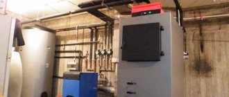
Steam boiler structure
A steam boiler is a container in which heated water evaporates and forms steam. As a rule, this is a pipe of various sizes.
In addition to the water pipe, the boilers have a combustion chamber (fuel is burned in it). The design of the firebox is determined by the type of fuel for which the boiler is designed. If it is hard coal or firewood, then at the bottom of the combustion chamber there is a grate. Coal and firewood are placed on it. Air passes from below through the grate into the combustion chamber. For effective draft (air movement and fuel combustion), a chimney is installed at the top of the firebox.
Ici Caldaie steam boiler design
If the energy carrier is liquid or gaseous (fuel oil, gas), then a burner is inserted into the combustion chamber. For air movement, an inlet and an outlet are also made (grid and chimney).
Hot gas from fuel combustion rises to a container of water. It heats the water and exits through the chimney. Water heated to boiling temperature begins to evaporate. The steam rises up and enters the pipes. This is how natural steam circulation occurs in the system.
Operating principle and types of steam boilers
If the purpose of heating installations is to heat water to heat the house while preventing it from boiling in the boiler tank, then the operation of a steam boiler solves the opposite problem. It consists of directing all the thermal energy of burning fuel to boil water and evaporate it. Some technological processes require elevated steam temperatures, so the third stage of the unit’s operation is its heating to this temperature (overheating). The main operating indicators of steam generators are pressure and productivity, which is expressed in tons per hour.
The designs of this type of thermal power equipment are different, but the principle of operation of a steam boiler remains unchanged: when burning liquid fuel or natural gas in the furnace, transfer all the heat of combustion to water passing through the heat exchanger in order to evaporate it and send it to consumers. According to the method of heat transfer in steam generators, heat exchangers are used:
- fire tubes (smoke tubes);
- water tube
They have one common feature: they are pipes manufactured in various installations of different sections and shapes. One of the media participating in the heat transfer process moves inside the pipes, and outside they are washed by the second medium. In fire tube heat exchangers, hot combustion products pass inside, heating the water in the boiler tank to a state of steam formation. Everything happens the other way around in a water-tube unit, where water circulates through coils, and it is heated from the outside by a burner flame and flue gases.
Classification of steam boilers
Steam boilers are classified according to several criteria. According to the type of fuel they operate on:
- gas;
- coal;
- fuel oil;
- electric.
By purpose:
- household;
- industrial;
- energy;
- recycling.
By design features:
- gas pipes;
- water tube
Let's look at how the design of gas-pipe and water-pipe machines differs.
Gas and water tube boilers: differences
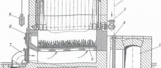
The container for generating steam is often a pipe or several pipes. The water in the pipes is heated by hot gases generated during fuel combustion. Devices in which gases rise to water pipes are called gas-tube boilers. The diagram of the gas-pipe unit is shown in the figure.
Diagram of a gas-tube boiler: 1 - fuel and water supply, 2 - combustion chamber, 3 and 4 - smoke pipes with hot gas that exits further through the chimney (positions 13 and 14 - chimney), 5 - grate between the pipes, 6 - water inlet , the output is indicated by the number 11 - its output, in addition, at the outlet there is a device for measuring the amount of water (indicated by the number 12), 7 - steam output, the zone of its formation is indicated by the number 10, 8 - steam separator, 9 - the outer surface of the container in which water circulates.
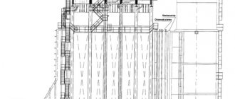
There are other designs in which gas moves through a pipe inside a container of water. In such devices, water tanks are called drums, and the devices themselves are called water-tube steam boilers. Depending on the location of the water drums, water tube boilers are classified into horizontal, vertical, radial, and combinations of different pipe directions. The diagram of water movement through a water-tube boiler is shown in the figure.
Diagram of a water tube boiler: 1 - fuel supply, 2 - firebox, 3 - pipes for water movement; the direction of its movement is indicated by numbers 5,6 and 7, the place of water entry - 13, the place of water exit - 11 and the place of discharge - 12, 4 - the zone where water begins to turn into steam, 19 - the zone where there is both steam and water , 18 - steam zone, 8 - partitions that direct the movement of water, 9 - chimney and 10 - chimney, 14 - steam exit through the separator 15, 16 - outer surface of the water tank (drum).
Gas and water tube boilers: comparison
To compare gas and water tube boilers, here are some facts:
- Size of pipes for water and steam: gas-tube boilers have larger pipes, water-tube boilers have smaller pipes.
- The power of a gas-tube boiler is limited to a pressure of 1 MPa and a heat-generating capacity of up to 360 kW. This is due to the large size of the pipes. They can generate significant amounts of steam and high pressure. An increase in pressure and the amount of heat generated requires significant thickening of the walls. The price of such a boiler with thick walls will be unreasonably high and not economically profitable.
- The power of a water-tube boiler is higher than that of a gas-tube boiler. Small diameter pipes are used here. Therefore, the pressure and temperature of the steam can be higher than in gas-pipe units.
Note: Water tube boilers are safer, more powerful, produce higher temperatures and can handle significant overloads. This gives them an advantage over gas-pipe units.
Drum boilers
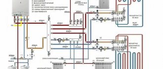
Water circulation in a forced-circulation drum boiler 1 Feed pump 2 Economizer 3 Rising pipes 4 Lower pipes 5 Drum 6 Superheater 7 To turbine 8 Circulation pump
Water supplied to the boiler by a feed pump (for example, a steam injector), passing through the economizer, enters the drum (located at the top of the boiler), from which, under the influence of gravity (in boilers with natural circulation), it enters the lower unheated pipes, and then into the heated lifting pipes, where steam formation occurs (the rising and falling pipes form a circulation circuit). Due to the fact that the density of the steam-water mixture in the screen pipes is less than the density of water in the downcomers, the steam-water mixture rises through the screen pipes into the drum. It separates the steam-water mixture into steam and water. The water goes back into the downpipes, and the saturated steam goes into the superheater. In boilers with natural circulation, the frequency of water circulation through the circulation circuit is from 5 to 30 times. Boilers with forced circulation are equipped with a pump that creates pressure in the circulation circuit. The circulation rate is 3-10 times. Boilers with forced circulation have not become widespread in the post-Soviet space. Drum boilers operate at a pressure less than critical.
Additional elements of the unit
The design of a steam boiler may include not only a combustion chamber and pipes (drums) for circulating water and steam. Additionally, devices are used that increase the efficiency of the system (raise the steam temperature, its pressure, quantity):
- Superheater - increases the steam temperature above +100ºC. This in turn increases the efficiency and efficiency of the machine. The temperature of superheated steam can reach 500 ºC (this is how steam boilers work in nuclear power plants). The steam is additionally heated in the pipes into which it enters after evaporation. Moreover, it can have its own combustion chamber or be built into a common steam boiler. Structurally, convection and radiation superheaters are distinguished. Radiation structures heat steam 2-3 times more than convection structures.
- Steam separator - removes moisture from steam and makes it dry. This increases the efficiency of the device and its efficiency.
- A steam accumulator is a device that takes steam from the system when there is a lot of it, and adds it to the system when there is not enough or little of it.
- A device for water preparation - reduces the amount of oxygen dissolved in water (which prevents corrosion), removes minerals dissolved in water (using chemical reagents). These measures prevent pipes from becoming clogged with scale, which impairs heat transfer and creates conditions for pipes to burn out.
In addition, there are valves for draining condensate, air heaters, and, of course, a monitoring and control system. It includes a combustion switch and switch, automatic regulators of water and fuel flow.
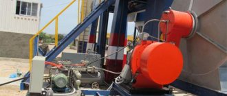
Steam generator: powerful steam engine
A steam generator is a steam boiler that is equipped with several additional devices. Its design includes one or more intermediate superheaters, which increase its operating power tens of times. Where are powerful steam engines used?
The main application of steam generators is in nuclear power plants. Here, with the help of steam, the energy of the decay of an atom is converted into electricity. Let us describe two methods of heating water and generating steam in a reactor:
- Water washes the reactor vessel from the outside, while it heats itself and cools the reactor. Thus, steam formation occurs in a separate circuit (water is heated against the walls of the reactor and transfers heat to the evaporation circuit). This design uses a steam generator - it acts as a heat exchanger.
- Pipes for heating water run inside the reactor. When pipes are fed into the reactor, it becomes a combustion chamber, and the steam is transferred directly to the electric generator. This design is called a boiling reactor. A steam generator is not needed here.
Steam generator for a nuclear power plant
Industrial steam units are powerful machines that provide people with electricity. Household units also work in the service of humans. Steam boilers allow you to heat a house and perform various work, and also provide the lion's share of electrical energy for metallurgical plants. Steam boilers are the basis of industry.
What else to read:
3.5. DE series steam boilers
The brand of vertical water tube boilers of the DE series indicates a D-shaped unit with natural circulation, which is designed to produce saturated and superheated steam with a temperature of 225 °C. Steam boilers of this series have several standard sizes, providing a working steam pressure of 1.4 MPa and a nominal steam output of 4; 6.5; 10; 16 and 25 t/h.
The boilers are specialized for burning gas and fuel oil, which makes it possible to more fully realize the benefits of these high-calorific fuels. A characteristic design feature of DE series boilers is the location of the combustion chamber (Fig. 3.7) on the side of the convective pipe bundle, which prevents heating of the upper drum and significantly reduces the area of the enclosing surfaces. Boilers of this series of all standard sizes have a single transverse profile. With a combustion chamber width of 1,790 mm and an average height of 2,500 mm, the boilers differ only in the length and movement pattern of the steam generator in the convective flue.
The combustion chamber of the boiler is completely shielded and separated from the convective bundle of pipes by a gas-tight partition 7, made, like all heat-receiving surfaces of the boiler, from pipes with a diameter of 51 x 2.5 mm. In the rear part of the partition there is a window (festoon) for the passage of the steam generator into the convective bundle, which is formed by corridor-positioned vertical pipes. The pipes of the right screen, which also covers the floor and ceiling of the combustion chamber, as well as the left side screen (partition 7 and festoon) and the convective beam are rolled directly into the upper and lower drums. The rear screen pipes are welded to the lower and upper manifolds with a diameter of 159 x 6 mm.
Front screen of steam boilers DE-4; -6.5; -10 is similar to the rear screen and differs only in the absence of part of the pipes in the middle part (to accommodate the burner embrasure and the manhole combined with the explosion valve). For DE-16 and DE-25 steam boilers, the front screen is formed by four pipes connected directly to the upper and lower drums. Under the combustion chamber is covered with a layer of refractory brick. On the front wall of steam boilers of the DE series, one gas-oil burner is installed: on DE-4 boilers; -6.5 and -10 — vortex burners GM-2.5; GM-4.5; GM-7 thermal power, respectively, is 2.5; 4.5 and 7 Gcal/h [I]; the DE-16 boiler uses a GM-10 burner with a cylindrical embrasure and a thermal power of 10 Gcal/h;
on the DE-25 boiler there is a two-stage combustion chamber with a GM-16 burner with a thermal power of 16 Gcal/h.
The movement of steam generators in steam boilers of the DE series is shown schematically in Fig. 3.5 Flue gases, i.e., fuel combustion products, from the combustion chamber enter through a window in the partition into the convective bundle of pipes. Boilers with steam capacity 4; 6.5 and 10 t/h have a longitudinal partition in the convective tube bundles (see Fig. 3.5), which ensures the rotation of the steam generators in the bundle and their exit through the rear wall of the boiler. Boilers with a steam capacity of 16 and 25 t/h do not have such a partition (see. Fig. 3.5 The transfer of GHG from the front part of the boilers to the economizer located at the rear is carried out by a gas box located above the combustion chamber.
The contours of the side screens and the convective bundle of pipes of all boilers (as well as the front screen of boilers with a steam capacity of 16 and 25 t/h) are directly connected to the drums, and the contours of the rear screen of all boilers and the front screen of boilers with a steam capacity of 4; 6.5 and 10 t/h - through intermediate collectors, with the lower one located horizontally and the upper one inclined.
Boilers with steam capacity 4; 6.5 and 10 t/h do not have staged evaporation, and boilers with a steam capacity of 16 and 25 t/h are equipped with a staged evaporation system with an intra-drum salt compartment (see Fig. 3.7).
The first rows of convective bundle pipes along the steam generator are allocated to the second stage of evaporation. The drainage system of the salt compartment circuit consists of unheated pipes with a diameter of 159 x 4.5 mm (two pipes for a boiler with a steam capacity of 16 t/h and three pipes for a boiler with a steam capacity of 25 t/h). The downward system of the first stage of evaporation consists of the last convective bundle tubes along the gas flow.
Shields and visors installed in the upper drum are used as separation devices for the first stage of evaporation, directing the steam-water mixture from the screen pipes to the water level. To equalize steam velocities along the entire length, the boiler drum is equipped with a perforated steam receiving ceiling. On all boilers, except for the boiler with a steam capacity of 4 t/h, a horizontal louvered separator is installed in front of the steam receiving ceiling. Feed water enters the drum water space through a pipeline
To carry out intra-boiler water treatment, an aqueous solution of trisodium phosphate is introduced through a pipeline into the upper drum, which, entering into a chemical reaction with the salts dissolved in the boiler water, transforms them into an insoluble state. The resulting sludge enters the lower drum through downpipes.
Rice. 3.7. DE series steam boiler ;
1, 10 - upper and lower drums; 2 - pipeline for phosphating; 3 - pipeline for supplying feed water; 4 — salt compartment of the drum; 5 - pipeline for purge; 6 - burner; 7 - gas-tight partition; 8 — right screen; 9 - combustion chamber; 11 - convective tube bundle; 12 — blowing device
In the lower drum there are perforated pipes (pipeline for purge), through which all boiler purge is carried out for boilers with a steam production capacity of 4…10 t/h. On boilers with a steam production capacity of 16...25 t/h, only periodic blowing of the boiler is carried out through these pipes, while continuous blowing is carried out from the salt compartment of the upper drum.
To monitor the operation of the boiler, a boiler pressure gauge and two water indicator columns are located in the upper drum. In addition, two safety valves, a main steam shut-off valve, and steam extraction pipelines for auxiliary needs are installed on the upper drum. The boilers are equipped with blowing devices to clean heating surfaces from contamination. The lining of the side walls of the boiler is made of pipes and consists of fireclay concrete on a grid and insulating slabs. To reduce air leaks into the gas path of the boiler, the outside of the pipe lining is covered with metal casing welded to the frame. The tail heating surfaces of DE series steam boilers are free-standing standard cast iron economizers. The efficiency of these boilers depends on the performance and ranges from 90.3...92.8% when operating on gas fuel and 88.7...91.4% when operating on fuel oil.