Functions of automatic ventilation cabinet
Thanks to the improvement of equipment in the field of ventilation automation, it has become possible to eliminate the human factor from the operation of the ventilation control cabinet.
Automation guarantees a high level of safety due to the enormous functionality provided by ventilation controlled by cabinet actuators. Wide range of ventilation control cabinet options include:
- Connection of any ventilation elements with different physical characteristics and different ports for system installation.
- Ability to control network voltage.
- Control of special electric valves to ensure continuous power in the electrical network. Increases the operation of devices, eliminating their overheating, short circuits, and overloads.
- Control of set parameters for the room and fan speed.
Standard Features
A typical ventilation automation cabinet has the following functions:
- Control of the heating temperature of an individual element of the ventilation system.
- Control over the operating parameters of the air valve drive.
- Monitoring the cleanliness of air filters. When dirty, an audible signal is sent to the ventilation equipment control unit.
- Controlling a valve to move air flows to maintain a given room temperature.
- The ventilation equipment unit is controlled manually, turning it on and off.
- Elimination of overheating and short circuit of the pump motor.
- Using indicator lights, you can obtain information about the operation of the system as a whole.
- Possibility of extending the stop time of movement of both supply and exhaust air using SHUV fans (ventilation control cabinet).
- Maintaining a log of failures in the operation of the forced ventilation system.
- Control of icing of parts of freon coolers.
Advanced Features
The set of advanced functions depends on the specific model of the SHUV device. Often used functions such as:
- Control of special valves to regulate pressure when the fan belt breaks.
- Automatic control of the amount of carbon dioxide.
- Saving all work data in logs after a power outage.
- Control over a special air flow mixing chamber.
- Programming a week in advance of the entire work process.
- Monitoring the parameters of the cooling valve.
- Control using an electric heater.
- Using the remote control.
- Implementation of effective work with sensors designed to monitor various room parameters using the cascade method.
Ventilation and central air conditioning
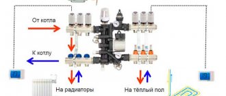
The typical technological diagrams presented here for ventilation and central air conditioning systems operating under the control of the S2000-T controller are basic. This means that the user can make changes to them at his own discretion. For example, you can enter pre-heating of air blinds into the configuration, or change the type of control using a duct sensor to cascade control using a room temperature sensor. And using a block of conditions, you can, for example, introduce discrete control of the fan speed, including reducing the fan speed provided that the outside temperature drops below a fixed setpoint. The technological diagrams show the piping of heaters using two-way valves. This does not prohibit the use of heater piping with three-way valves. The control algorithms for heat recovery units support both heat recovery in winter and cold recovery in summer.
symbols are used on technological diagrams of ventilation systems:
devices and components:
THOSE
- temperature sensor. Depending on the location on the diagram, it can be a street, channel, room or return water sensor (submersible or overhead type).
FG
– air damper drive. As a rule, two-position actuators are used, and in the presence of a water heater, two-position actuators with a mechanical return spring are used.
PDA
– differential pressure switch. Depending on the installation location, it can be a filter clogging sensor if pressure switch receivers are installed before and after the filter, or a belt break sensor if the relay is installed near the fan. In the latter case, a normally closed contact is connected to the S2000-T controller.
P
– proportional drive of the water heater valve (two- or three-way). To work with the S2000-T controller, a standard drive controlled by a voltage of 0...10 V is required.
Y1
– proportional drive of the water cooler valve (as a rule, always three-way), controlled by a voltage of 0...10 V.
TZA
– a capillary air protective thermostat is installed immediately behind the heater (mounted on the fins of the heat exchanger) and is adjusted to an operating temperature of at least 5 °C. Its normally closed contact is connected to the S2000-T controller.
M
– power circuits for controlling the circulation pump.
Emergency mode
– a state of the system in which some predetermined conditions are violated. In this mode, the controller operates according to a standard emergency algorithm or according to an algorithm specified by the user.
Blocks are supported as standard when the return water temperature drops below a preset setpoint and when the air safety thermostat is triggered, as well as when the temperature sensor malfunctions. In this case, the controller performs the following actions:
- generates the “Crash” event;
- gives a sound signal;
- gives a command to close the air dampers;
- gives a command to open valve P1;
- gives a command to stop fan P1.
Among the supported interlocks there are also interlocks for a broken fan belt, for the activation of a thermal contact of the motor windings, and for the fact that the maximum permissible winding currents have been exceeded. In this case, the controller:
- generates the “Crash” event;
- gives a sound signal;
- gives a command to the system to switch to standby mode.
Standby mode
– the state of the system in which:
- the air damper is closed;
- the fan is stopped;
- the set return water temperature is maintained according to the set point.
Switchboard for servicing automation with water heaters
Automatic supply ventilation is designed to ensure safety during the operation of air heating devices and room ventilation. The main device of the panel is the Swedish-made AQUA controller. The remaining components are installed to solve the following issues:
- control fan devices;
- maintain the specified temperature of the air masses;
- switch operating modes;
- control valve drives with return springs, ensuring closure of air intake valves in the event of fan units being turned off or a phase short circuit to the housing;
- control the operation of the water circulation pump in the heater installed in the piping unit;
- monitor the water temperature in the return line under different operating modes, when the heater is turned off;
- turn off the power supply when the air filter is dirty.
Automation of ventilation allows you to solve complex problems in any conditions and under various operating modes of equipment. Each air ventilation circuit is installed with an automatic process control system.
In conclusion, we note the main points that you should pay close attention to when purchasing devices for equipping an automatic control panel for a building ventilation device. The main selection criterion is the reliability of components
Be sure to ask the manager for a quality certificate for these devices, as well as a guarantee from the manufacturer of the ventilation panels and each individual part. Pay attention to the availability of a production base for repairs, warranty service of ventilation equipment, and an automatic process control scheme
The main selection criterion is the reliability of the components. Be sure to ask the manager for a quality certificate for these devices, as well as a guarantee from the manufacturer of the ventilation panels and each individual part
Pay attention to the availability of a production base for repairs, warranty service of ventilation equipment, and an automatic process control scheme
Each device must have a passport, instructions, and connection diagram. Today on the ventilation equipment market, various manufacturers offer a varied range of components and circuit diagrams for ventilation panels. Having made the right choice and performed high-quality installation of automatic cabinets, you will receive reliable, safe equipment for quite a long time.
Installation of automation for ventilation systems.
Automation of ventilation systems is used to more effectively control the climate, ensure the required quality of air treatment and protect ventilation units from breakdowns.
Depending on the installed ventilation system, automation is installed with different cabinet configurations:
- Automatic supply ventilation: an automation panel is being installed, which provides for equipping the system with air inflow sensors, providing analysis of the quality of air exchange in the network, the degree of air purification, etc.
- Automatic exhaust ventilation: to ensure exhaust (contaminated) air extraction, a control cabinet is installed, which includes the installation of sensors for measuring air flow speed, network pressure, etc.
For more details, see: automation of ventilation systems.
Description of the functional diagram
The functional diagram shows the principle of automated control of supply and exhaust ventilation, drawing DP AT061 K897 E2.
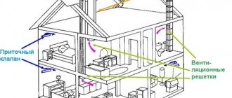
During operation of the system, outside air enters the air supply unit through the air intake grille, passes through the open air valve, and then passes through the silencer into the pocket filter section. After this, the purified air passes through the heating section and is heated to a temperature of 22°C during winter operation. The air then passes through the cooling chamber and is cooled during summer operation. Then the air enters the fan section, where pressure is created and, after the silencer section, it enters the serviced premises through air ducts.
The supply air temperature is measured by sensor (16a). The measured temperature is transmitted to the control panel, and the controller generates a signal to the shut-off and control valves (8a, 11a).
The system provides filter clogging monitoring. When the pressure difference before and after the filter exceeds 100 Pa, the sensor (4a) will close its contacts and this signal will turn on the light alarm and if the filter is not cleaned or replaced within 72 hours, it will stop the system.
The system provides protection for heaters from freezing. When the water temperature in the return pipeline drops below 20°C, a signal from the sensor (5a) is sent to the control panel. Protection for air temperature after the heater is also provided. Sensor (9a) will generate a signal at a temperature of 5°C which will be sent to the control panel. When one of the signals is received, the fan stops, the external air valve interlocked with it closes and the three-way valve (8a) fully opens to maximize the coolant flow. Thus, the movement of cold air stops, and the circulation of coolant through the heater continues. Due to the lack of heat removal, the temperature of the cooled coolant begins to rise. When the coolant temperature reaches 50°C, the fan turns on, the outside air valve opens, and the operation of the air heater resumes.
The outside air temperature sensor (1a) switches between winter and summer operating modes. Depending on the operating mode, the air is either heated or cooled. To regulate the temperature of the supply air, a control unit for the supply of coolant to the air heater is used. The diagram of the control unit УУ1 is shown in Figure 3.
Figure 3 - Diagram of the control unit УУ1.
- 1 — Surface-mounted thermostat to protect the heater from freezing in water.
- 2 - Circulation pump.
- 3 - Indicating dial pressure gauge.
- 4 - Indicating dial thermometer.
- 5 - Filter.
- 6 — Surface-mounted return water temperature sensor.
- 7 - Balancing valve.
- 8 - Shut-off ball valve.
- 9 — Three-way valve with electric drive.
Water from the heating network passes through a balancing valve and filter and enters the heat exchanger, gives off some of the heat and returns to the heating network. The circulation pump mixes supply water with return water, which enters the supply pipeline depending on the position of the control valve. The control valve increases or decreases the flow of return water into the heat exchanger depending on the supply air temperature or the return water temperature, which is measured by a clamp-on temperature sensor. An overhead thermostat protects the heat exchanger from freezing of the coolant. If the water temperature is below 0°C, the coolant will freeze and lead to rupture of the heat exchanger tubes, which cannot be repaired and is expensive to replace.
In the summer operating mode, the coolant supply control unit is used to control the coolant supply to the air cooler. The control unit for the supply of coolant to the air cooler UU2 is shown in Figure 4.
Figure 4 — Coolant supply to air cooler УУ2.
- 2 - Circulation pump.
- 3 - Indicating dial pressure gauge.
- 4 - Indicating dial thermometer.
- 5 - Filter.
- 7 - Balancing valve.
- 8 - Shut-off ball valve.
- 9 — Three-way valve with electric drive.
Water from the refrigeration machine passes through the balancing valve and filter and enters the cooling section, is heated and returned to the heating network. The circulation pump mixes supply water with return water, which enters the supply pipeline depending on the position of the control valve. The control valve increases or decreases the flow of return water into the heat exchanger depending on the supply air temperature.
Sensors and Transducers
Sensors are elements of ventilation automation systems that serve to obtain information about the real state of the controlled object. With their help, feedback is provided between the control system and the object according to the following parameters: temperature, pressure, humidity, etc.
In order for information from the sensor to be transmitted to the system in the form of a digital code, each sensor is equipped with a converter.
The optimal locations for installing the sensors are indicated in the instructions supplied with them.
Temperature sensors can be for indoor or outdoor use; overhead on the pipeline (for monitoring the surface temperature of the pipeline) or duct (for measuring the air temperature in the air duct). Indoors, temperature sensors are installed in neutral places relative to sources of heat or cold, outside the building in places where the sensor will be protected from wind or direct sunlight.
Humidity sensors are a unit with an electronic device that measures relative humidity and converts the data into an electronic signal. There are external and internal versions. They are installed in places with stable humidity conditions; they are not allowed to be installed near heating radiators, air conditioning units, or near sources of moisture.
Pressure sensors are divided into pressure switches (mechanical measurement of differential pressure and electrical conversion) and analog pressure sensors (conversion of pressure directly into an electrical signal, for example, using piezo elements). Both are used to measure pressure at one point and the difference in pressure at two points.
It is advisable to install both external and internal sensors in twos or more, for example, on the north and south sides of the building. In modern systems, all external climate sensors are combined into a single weather station.
Flow sensors measure the speed of a liquid or gas in a pipeline or duct. Liquid flow is calculated using a formula inside the processor unit based on the pressure difference and other parameters (temperature, pipeline cross-section, density).
Forced ventilation control
The automatic control system is very important for the ease of use of mechanical ventilation. It performs the following functions:
- Starting and stopping ventilation at the operator’s command;
- Allows you to maintain the conditions set before starting work;
- Allows you to easily find trouble spots;
- Controls the load on individual elements to avoid breakage;
- Allows you to monitor the condition of the ventilation system.
Automation elements
Any automation system includes an electrical panel. It is the place where the ventilation control panel is mounted. The simplest option is the lever responsible for turning the ventilation and indicator on and off. But for ease of control, industrial automation with an element of automation is used. It allows you to monitor the slightest changes in the ventilation system: determine the level of filter contamination, turn on the heater if necessary, etc. To make all this possible, pressure, temperature, thermostats, hydrostats, etc. are used.
Microprocessor controller
One of the elements of ventilation automation is a microprocessor controller. It includes a screen with a simple menu thanks to which you can monitor changes and adjust ventilation operating parameters.
Signals about changes in the state of the system and air in the room are sent by sensors. There are mainly two types used:
- Temperature;
- Pressure meters.
Temperature sensors, in turn, are divided into channel and room. The former are used to determine the air temperature inside the ventilation ducts. Room meters are used to determine the temperature inside a room. They work as follows: the sensor sends a signal to the control panel, where the data is compared with the established ones and, depending on the results obtained, changes occur in the ventilation operation.
Pressure meter
Important elements of automation are pressure sensors; they allow you to track disturbances in air movement in the air duct network. The device is triggered in the event of the slightest changes in pressure, which makes it possible to determine the degree of contamination of the filters and recuperator, and protects against false starts of the heater and other heating elements.
An air valve servo drive is installed in any automation system. It is necessary to regulate the position of the air dampers. In addition, it serves to prevent freezing of the heat exchanger; in the case of supply and exhaust ventilation, it regulates the degree of recirculation.
Sensor installation
It is important to correctly place all sensors, since the quality of operation of the automatic control system will depend on this. If it uses surface-mounted sensors, they should be mounted directly on the pipe. For correct operation of duct sensors, they are installed perpendicular to the air flow. Indoor ones should be installed at a height of 1.5-1.8 meters from the floor, where they will not be affected by extraneous sources of heat or cold. As for atmospheric sensors, they are mounted outside the building, on the leeward side, in the region of 2/3 of the building’s height.
temperature sensor
It is important that the place where the sensor will be placed should not be exposed to vibration.
To start the system for the first time, do the following:
- It is necessary to check the quality of connection of all automation elements;
- Set the threshold for the air safety thermostat to +10 degrees Celsius;
- Set the response threshold of the water protective thermostat to +25 degrees Celsius and check the operation of the device if the temperature of the thermostat drops;
- If the automation system includes a water heater, you need to set the time during which the heater will heat up and the blower will go into operating mode - setting the time relay;
- Depending on the equipment, you need to set the response threshold of the pressure sensor-relay for the fan and filter.
- You also need to configure the control panel.
Before starting work, you should carefully study the technical description of all equipment. And check the serviceability of all devices.
Purpose of ventilation control cabinets
Today, the ventilation control cabinet is an integral part of the air exchange system. It greatly facilitates the operation of equipment to provide fresh air to the room or utilize exhaust gases.
When purchasing a SHUV distribution unit, you should be guided by the control functions for specific ventilation, according to its operating conditions.
For a ventilation system that provides smoke removal from premises, a SHUV is required, which will provide increased safety and control the air temperature in the room and its humidity. And also maintain the required parameters at normal levels and move air masses at a certain constant speed.
The purpose of the ventilation control cabinet depends on the type of air exchange system:
- With recovery or purification of harmful air substances in the work area.
- With electric heater.
- With water heater.
- With smoke function.
- Exhaust, supply or supply - exhaust ventilation (SHU PVV).
All ventilation control cabinets operate in two modes:
- Summer mode. Indicates that air temperature control is disabled. When the supply air temperature drops, the automation switches on the protection mode according to the parameters entered in advance. Temperature control is carried out using sensors.
- Standby mode.
To control one fan, it is possible to use the SHUV1 smoke removal cabinet. To control several fans, a cabinet of the ShSAU-VK type is suitable. The price directly depends on the number of controlled fans.
Sensors
The following types of sensors are used in the air conditioning system:
- Sensors for monitoring the temperature of supply air and indoor air;
- Sensors for monitoring the concentration of carbon dioxide CO2 in indoor air;
- Air humidity control sensors;
- Sensors for monitoring the condition and operation of equipment (pressure and air flow speed in air ducts, temperature, pressure or flow sensors for devices with liquid circulating through pipelines, etc.).
The output signals from the sensors are sent to the control cabinet to analyze the received data and select the appropriate algorithm for the operation of the air conditioning system.
Manufacturing materials
When designing the design of venous system equipment, the operating conditions in which they will function uninterruptedly are taken into account. Cabinet interiors are rarely installed outside the panel.
When developing a project, the following are taken into account:
- ambient temperature during operation. If the temperature regime is not observed, the performance characteristics will deteriorate. The material will quickly melt, wear out, and the power equipment located inside will become unusable;
- the humidity regime must also be ensured within standard values so that short circuits do not occur on electrical parts;
- providing altitude relative to sea level. This indicator affects the forced ventilation device, since heat exchange conditions worsen when atmospheric pressure parameters change.
When installing equipment, the environment inside the cabinet, compared to the outside air, changes. Based on the results of the research, cabinets for equipping ventilation systems with opening lids are produced. But they often use the current climate control standards for the corresponding external operating parameters, while taking into account:
- working temperature;
- temperature indicators inside the cabinet and outside the technical device;
- indicator of the radiated power of the equipment;
- specified altitude above the level of the Baltic Sea.
When choosing a material, you should take into account the dimensions of the designed cabinet, the type of installation, and then select one of the existing materials, set the height relative to sea level, taking into account the environmental indicators and the design power, which exceeds the nominal by 5%.
The main tasks of automation for ventilation
Since the modern market offers a large number of various technical devices for ventilation automation, the range of their functions is also extremely wide.
Main functions of the control module equipped with elements of electronic intelligence:
- Maintaining the specified parameters of the microclimate of the interior - air temperature and humidity, carbon dioxide saturation, etc.
- Possibility for the operator to remotely control the fans, turn them on and off remotely.
- Implementation of automated control over the sensors of all components and assemblies of ventilation equipment.
- Independent transfer of equipment to summer or winter mode.
- Monitoring the level of contamination of filter devices with the function of signaling the need for cleaning.
- Opening and closing air duct dampers, adjusting the performance of supply and exhaust fans.
- Cutting off the fresh air supply when the fire alarm is activated.
- Turning off the power supply in emergency situations - sudden surges or drops in voltage. This allows you to prevent failure of devices, sensors and individual components of the ventilation system.
Additional functions
Modern manufacturers, in order to fully satisfy customer requests, pay special attention not only to the reliability of the equipment they produce. An important factor in the competition for consumers is equipping products with as much additional functionality as possible.
Today, highly intelligent functions such as:
- Connecting ventilation to a single electronic “smart home” control controller.
- Manage settings via Internet applications, using Wi-Fi and Bluetooth.
Equipped with modern functionality, automatic equipment becomes clear and easy to operate, like other household appliances.
What is automation for ventilation systems
Today, automatic ventilation control systems are represented by a large complex of various technical devices. All of them, from thermostats to complex computerized modules, are designed to facilitate the management and control of the operation of forced ventilation systems. The variety of equipment makes it possible to solve automation problems at any facility, regardless of its characteristics and purpose.
Based on operational and technical requirements, different approaches to the manufacture of automated ventilation control panels are possible:
- At some facilities, you can get by with standard modules produced in the form of cabinets with control devices installed in them.
- In other cases, installers have to manually assemble complexes adapted for complex supply and exhaust ventilation systems, taking into account specific tasks.
The difference in approaches is due to the need to ensure effective ventilation and create comfortable conditions for residents or workers in the interior of the building, regardless of the time of year and external weather conditions.
Important! In large shopping and entertainment complexes, in educational and administrative buildings, in large industries, the installation of equipment for automation of ventilation systems allows you to eliminate possible operational failures and minimize the influence of the human factor.
The operation of ventilation mechanisms is controlled using a set of sensors installed indoors. Some of them operate on the principle of a thermostat - as the temperature inside the building rises, fans automatically turn on, thereby ensuring a flow of fresh air.
We recommend that you read: Types of built-in 90 cm hoods for the kitchen
Modern automated systems are equipped with elements of artificial intelligence and more complex instrumentation.
Structurally, similar modules consist of three groups of nodes:
- Sensors are devices that transmit information about the environment - thermostats, air humidity meters, gas analyzers. They transmit the collected data to the analyzing center.
- The control center collects and processes information coming from control sensors and, based on the analysis obtained, issues commands to control mechanisms to change the operating mode.
- Actuators are units that perform mechanical actions. This group includes: fan speed converter, servo drives for adjusting the position of valves, etc.
Control centers analyze the ratio of oxygen and carbon dioxide in the air, the percentage of humidity, and, if necessary, issue a command to ventilate the room. When a fire is detected, highly intelligent electronics independently block the flow of fresh air, preventing the spread of fire.
In normal mode, automation ensures the smooth functioning of all components and mechanisms of ventilation systems without the involvement of an operator.
Computerized modules transmit information about the operating mode and sensor readings to a single control panel. This allows the operator, if necessary, to adjust the operation of the automation and change settings remotely.
Note! Thanks to the use of automation, a much smaller number of technical specialists can control the operation and maintain ventilation with installed automation.
Depending on the specific situation, one of 3 device control modes is used:
- Manual. Ventilation control is carried out by an operator located directly in the control room or at a remote control panel.
- Autonomous. The equipment operates in accordance with the established settings, regardless of other engineering systems installed in the building.
- Auto. Control devices are integrated into the overall control of all engineering complexes of the building. The ventilation operation is synchronized with other devices and sensors located in the house - for example, with a fire alarm and other emergency sensors.
We recommend that you read: Do-it-yourself natural ventilation system in a private house
Thus, the automated complex plays the role of a control center. It starts the ventilation, stops it, processes sensor readings and sets the desired mode depending on temperature, humidity and other parameters.
The main tasks performed by automatic ventilation
If certain malfunctions occur, the automatic control of the hood is triggered, ensuring high safety:
- Solving problems of managing and monitoring the normal operation of the circuit. An emergency alarm must be installed for hazardous operating modes of equipment. New developments make it possible to control the operation of the circuit remotely. The operator monitors the functioning of the device, can make adjustments, and set optimal modes.
- Carrying out individual analysis and monitoring of the operation of each individual mechanism and the overall activity of the ventilation circuit. The device’s sensors deliver information, and the automation examines the situation and makes adjustments to the operation of the ventilation equipment. In the event of an accident, a signal is sent to the start button to turn off the equipment.
- Protects the valves and water heating circuit from low temperatures and does not allow the temperature to drop to a critical level.
- Provides the ability to control the room ventilation process by switching equipment operating modes. When there are changes in load or room temperature, the control system is able to reduce the speed of fan rotation, completely turn off the equipment and maintain comfortable conditions in the serviced room.
- In the event of a short circuit and other emergency situations, it blocks the mechanisms to prevent fire and electric shock to people.
The complexity of the work performed depends on the completeness of the automatic device panel.
Functions of automatic ventilation cabinet
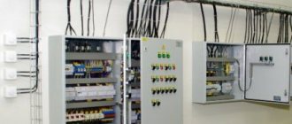
ventilation control cabinet "Rubezh-4A"
Capabilities of ventilation control cabinets:
- maintain the required constant power of the electrical network;
- allow you to conveniently connect lines of different power voltages to different terminal blocks;
- control the intensity of fan rotation, start them smoothly and prevent phase imbalance;
- equalize power, preventing equipment overheating, overload and short circuits;
- control the voltage in the network autonomously, remotely or locally.
The supply and exhaust ventilation control cabinet operates in standby or summer modes. In summer mode the air temperature is not controlled. When the supply air temperature is low, the cabinet automation switches the supply ventilation control to protection mode.
Standard Features
- Manual stop and start;
- compatible with temperature sensors of supply air, outside air, and return coolant;
- records the temperature of fan motor contacts;
- regulates the function of the air valve drive;
- prevents short circuits and overloads of the pump motor;
- controls the heat supply valve drive;
- prevents freezing of water heaters and freon coolers;
- prevents overheating of the electric heater;
- prolongs the shutdown of the supply air fan;
- gives signals about the need to clean the air filters;
- stops and de-energizes equipment during a fire alarm;
- notifies with the help of light indication about the operation of the system;
- records accidents in a special log.
Advanced Features
- Prevents pressure drops when the fan belt breaks;
- Provides frequency conversion for fans;
- Regulates indoor air temperatures in a cascade manner;
- compatible with the temperature sensor on the hood;
- notifies about an accident with a light indication;
- connection of remote control is possible;
- controls the operation of the air valve;
- provides connection of additional fans;
- two-phase control of the compressor-condenser unit;
- five-phase control by electric heater;
- controls the mixing chamber;
- prevents freezing of the recuperator and rotary regenerator;
- controls air humidifiers;
- programmable for 7 days;
- controls the cooler valve;
- controls recirculation dampers;
- if the heating power is insufficient, reduces the rotation speed of the fan blades;
- retains data in memory after power failure;
- controls carbon dioxide levels.
Upon request, manufacturers equip the cabinet for automatic ventilation control with additional features:
- work without sensors;
- recording reports on system operation;
- cold recovery;
- dispatcher remote or local control.
Elements of ventilation systems
The control system includes basic elements such as sensors, regulators and other actuators.
Sensors
Using sensors, you can obtain information about the state of the required object based on various parameters (temperature, pressure, humidity, etc.) and control it in the event of the slightest system failure. Sensors must be selected strictly in accordance with the conditions of a particular ventilation (operating conditions, range and degree of accuracy of measurements, etc.).
Temperature sensors are made for outdoor and indoor use; they can show the temperature on the surface of the pipeline or inside the channel (air duct). They are attached either to the pipes themselves (on their surface) - external ones, or perpendicular to the moving air flow in the pipe, air duct - duct sensors. Atmospheric sensors are installed outside the building, above its middle, on the leeward side, and indoor types of sensors must be mounted indoors, at a distance from the floor of at least 1 - 1.5 m.
Ventilation and heating system sensors
Ventilation control also depends on sensors that regulate the degree of humidity; they can be used for room or duct purposes. Outwardly, they look like a block with a built-in electrical device that measures the relative humidity of the air and converts the received data into electronic signals. In order for the device to work more accurately, it must be installed at a certain distance from windows, heating devices, ventilation streams and sunlight.
Flow sensors are devices that measure the speed of flow (this can be either liquid or gas) in pipes and air ducts. The gas or liquid flow rate is calculated taking into account the cross-sectional area of the pipe.
Regulators
Regulators are necessary to control ventilation actuators. They receive signals from sensors, process their readings and activate the actuators of the ventilation system.
Control regulators for actuating ventilation mechanisms
Actuators
A device that begins its operation upon a command received from the regulator is called an actuator. They are divided according to the method of operation: electrical, mechanical, hydraulic, etc.
All processes that make up the entire ventilation control system are controlled through a device such as an electrical control panel.
Control panels (cabinets, unit) for ventilation systems
A control panel is a device that provides centralized control over technological processes in enterprises for various purposes (power plants for gas supply systems, water supply systems, electricity supply systems, etc.). This is a kind of remote control with instruments for measuring and monitoring various parameters, light indicators, control keys and mnemonic diagrams located on it.
The control unit is configured in such a way that visibility of the devices and quick access to them are taken into account as much as possible. Together with the control panel for the entire enterprise, group, unit, workshop and other panels can be installed in the system.
Control cabinets are also used in ventilation systems. Control, through cabinets, can be carried out by programmed micro controllers (automatically) and by manual adjustment of operating parameters.
The ventilation control panel is the basic unit of this system; it performs the following basic functions:
- Includes operation indication and the ventilation unit itself;
- Controls the supply fan;
- Adjusts the speed of the supply fan;
- Controls the air damper drive;
- Regulates temperature.
Control panels work with various types of equipment for ventilation systems. Thanks to it, it not only maintains a constant temperature and humidity of the room, but also increases the safety of operating equipment.
Ventilation is controlled by a remote control (panel) according to the parameters specified by the manufacturer; these can be standard and additional (advanced) functions. The cabinet regulates and records the contact temperatures of ventilation motors, controls the air and heat supply valves, slows down the stop time for the supply air exchange fan, gives signals about filter contamination, the entire operation of the system, prevents and records accidents, and performs many other tasks assigned to it.
Main components of the system
Designing such systems is a complex matter that requires certain knowledge and skills, so the ventilation automation cabinet must be configured by a specialist who understands this. To work with devices, you need to know the purpose of each node, the features of its operation and interaction with other elements. You need to have experience working with various devices and equipment from different manufacturers. That is why all the work must be done by professionals who have the necessary knowledge and experience.
Modern automation panels for ventilation systems include quite a lot of different equipment. All devices that are in any way involved in creating a control system can be divided into three groups:
- Touch sensors. These devices collect all kinds of information about the state of the system, reading the level of humidity, temperature, pressure and other important indicators. They provide an electrical signal that goes further into the system.
- Regulators and controllers. These devices are responsible for further analysis of the obtained data. They compare information with each other, as well as with established standards, conduct a logical analysis and, based on it, issue any commands to the system, enabling or disabling certain functions.
- Executive mechanics. These parts ensure the execution of received commands, causing devices to perform certain functions and actions.
Accessories
The fan control cabinet is equipped with a power supply, controllers, converters and a large number of on/off switches. The switches, in turn, are connected to electric heaters, heat recovery devices, fans, water heaters and refrigeration units. A mandatory element of the switchboard is a manual control unit, which assumes the functions of regulation and control in the event of a failure or malfunction of the automation. In addition, all cabinets are equipped with emergency alarm sensors that are triggered in the event of an emergency or pre-emergency situation.
A special role in monitoring the operation of ventilation systems is played by sensors, which are a kind of receptors and collect information about the performance of each node. With their help, you can get a clear picture of the pollution of air flows, their temperature and humidity, as well as the speed of movement of air masses and the speed of rotation of the fan blades. Temperature sensors are available in both digital and analogue versions, and when the temperature inside the system changes, they help switch the entire installation to another mode. Humidity sensors work on the same principle. The information received by the sensors is sent to automatic regulators, which, in turn, adjust the operation of key components of ventilation systems.
Based on their location, sensors are divided into external and internal. The first ones are often called atmospheric and are installed on the outside of buildings. Internal ones, in turn, are divided into channel and surface models. Ducts are installed inside air ducts on the walls or across the movement of air masses. Surface ones are placed on the surface of the nodes and remove parameters from these devices.
An equally important element of control cabinets are controllers. The devices receive information coming from sensors and process it automatically. After processing the parameters, the controllers send a signal to the main units of ventilation units, such as fans, heaters, refrigeration units, after which they change their operating mode. Functionally, the controller can either serve several devices or interact with only one of them. Universal models are often equipped with microprocessors, which makes them less bulky and can be easily placed in a small cabinet or stand.
Another element of the shield configuration is fan blade speed converters. Thanks to these devices, it is possible to regulate the number of engine revolutions, thereby significantly reducing the amount of electricity consumed by the installation. In addition to saving money, this leads to a significant reduction in wear on fan parts and extends the overall service life of the ventilation unit.
(no votes yet)