Selection of quality equipment
The battery itself is selected for a pre-purchased solid fuel boiler and the parameters are calculated so that it can easily accumulate the maximum thermal energy that was generated by the direct source of the required heat.
The priority and main criterion for choosing a modern and well-thought-out heat accumulator will be the boiler itself, if its operating time of heat supply and power are somehow limited:
- To generate heat only a single one-time load of any fuel and its further analysis by the installed full heating system for a whole day.
- A solar type storage device of a certain power required for stable operation of the boiler, where heat is collected exclusively during daylight hours and in a stably uniform or exclusively peak use.
The main indicator for choosing a good heat accumulator is the consumer himself, when there is a need to cover the established thermal load for a certain period of time.
It is necessary to purchase this device in accordance with individual needs, as well as the characteristics of the installed solid fuel boiler.
Design in advance what kind of heat accumulator you need so that it can fully perform the functions and tasks assigned to it to enhance and control the thermal energy generated by the boiler.
Multi-circuit heating systems with heat accumulators
Another undeniable advantage of the storage tank is the potential ability to operate it as a hydraulic gun.
This function is very necessary, since due to the fact that the tank body is equipped with at least four pipes, it becomes possible to select coolant with the desired temperature at one or another level of the storage tank. This will make it possible to equip a high-quality high-temperature circuit equipped with radiators, as well as heating with low temperatures, such as in a heated floor.
However, we should not forget about pumps that have heating control circuits, since the temperature at different levels of the storage tank at different times of the day is known to be different. At the same time, the function of the pipes is not limited to outlets for heating circuits. Several boiler systems equipped with different types can be connected to one heating accumulator.
Connection diagrams
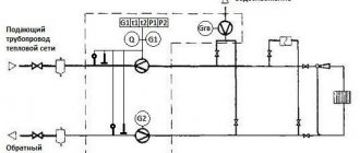
There are many ways to connect a solid fuel boiler with a heat accumulator and a heating system. But they are all derived from the basic circuit shown below. With its help, it is easy to understand how these units work in pairs, and then install everything yourself.
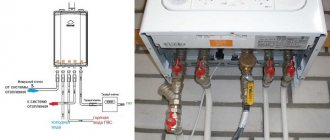
A heat source running on solid fuel has a traditional boiler circuit with a mixing unit, whose task is to prevent the supply of cold coolant to the boiler. Then the supply and return pipelines are connected to the buffer tank, respectively, from above and below. In the same way, a heating system, also equipped with a mixing unit, is connected to the heat accumulator. Its purpose is to maintain the required water temperature in the system, adding part of the hot coolant if necessary.
Important point. The actual performance of the boiler circuit circulation pump should be slightly higher than that of the heating network pumping unit. Compliance with this condition will allow the flows inside the heat accumulator to move in the right direction (shown in the diagram with white arrows).
In fact, the network pump will be more powerful than the boiler pump and here's why. The resistance of the network of pipelines and radiators is higher than 3-5 m of pipe from the solid fuel boiler to the heat accumulator. The unit needs higher power and pressure to overcome this resistance. Therefore, a weaker boiler circuit pump can provide higher flow rates, you just need to configure both units correctly. There are 2 options to resolve the issue:
- When using 3-speed pumps, you can adjust their performance by switching speeds.
- Place a balancing valve at the inlet of the return from the system into the buffer tank, which can be used to make adjustments.
Simultaneous heating of heating devices and layer-by-layer loading of a heat accumulator is possible when the flows inside the tank move horizontally with a slight predominance from the side of the solid fuel boiler. The question arises - how to check this? The answer arises: thermometers must be installed at both return inlets to the tank (as in the diagram) and adjustments must be made by switching pump speeds or rotating the balancing valve
Important condition: the three-way valve of the heating network must be fully opened manually
By adjusting it is necessary to ensure that the temperature at the inlet to the heat accumulator (T1) is less than at its outlet (T2). This means that part of the hot water goes to “charging” the battery. You can learn more about all the points from an expert by watching the video:
Alternative scheme
This scheme for connecting a buffer tank and a solid fuel boiler was proposed by one of the participants in the popular forum. Its peculiarity is that in the event of a power outage, the operability of the circuit remains, although you have to pay for this with increased diameters of steel pipes. The figure below shows the connection of a heat accumulator to a closed heating system, but during installation it is better to make it open, as the author himself says.
Briefly, the essence is this: thanks to the T-shaped input on top of the tank, the radiators are simultaneously heated and the thermal accumulator, made by hand, is “charged”. The boiler circuit pump is controlled by a clip-on sensor on the supply line, turning on the unit when it reaches a temperature of 60 °C. The circulation in the network depends on the room thermostat to which the network pump is connected.
Note. The proposed strapping scheme was tested by its creator from his own experience. All details of its installation and operation are described by the author on the forum
What is buffer capacity
In fact, a heat accumulator intended for a heating system is an ordinary metal tank of rated capacity, covered with a thermal insulation layer. In the simplest factory-made models there are only pipes for connecting the coolant and sleeves for installing thermometers. In more expensive buffer tanks, thermometers are already built-in, and the most expensive products are equipped with heat exchangers in the form of coils. The structure of such a heat accumulator is shown in the figure:
As you can see, the design of the buffer tank is not particularly complex, which is why various craftsmen have adapted to making it with their own hands, which is discussed in a separate topic.
The purpose of the coils is to heat water to provide hot water supply and connect alternative sources of thermal energy - solar collectors. It is clear that this function is in demand only under favorable weather conditions in the region of residence. In general, the buffer tank for a heating boiler is designed to solve the following problems:
- Creating conditions for the operation of a TT boiler with maximum efficiency and minimal emissions into the atmosphere.
- Heating and supply of drinking quality water to 1-2 consumers (optional).
Comfortable operation of the heat generator, when you do not need to add firewood to the firebox every 4-6 hours, including at night.
Most manufacturers of heating equipment operating on solid fuel indicate in the accompanying documentation that it is highly desirable to connect a heat accumulator to the TT boiler. The reason is this: the unit achieves its greatest efficiency when the operating mode is close to the maximum. And since the excess heat generated needs to be placed somewhere before being supplied to the heating system, this is where a buffer container with water comes in handy.
Without a thermal accumulator, we try in every possible way to “strangle” the thermal unit, limiting the supply of air for combustion. Not only does this reduce its efficiency to 40% (like a potbelly stove), but it also causes the release of toxic carbon monoxide into the atmosphere. Because of this, some European countries have banned the burning of wood and coal in heating boilers without a buffer tank.
With more rare visits to the furnace room, everything is clear: the heat accumulated in the tank will be spent on heating the house for a long time, provided that its volume is correctly calculated. In addition, when a solid fuel boiler works together with a heat accumulator, the likelihood of overheating and boiling of water in the unit jacket is reduced to almost zero.
In addition to interacting with wood heat generators, heat accumulators can also be used with electric boilers. This makes sense when the electricity consumed at night is calculated at a tariff that is 2-3 times lower than usual. During the period of time that this tariff is in effect, the electrical installation will be able to fully “charge” the thermal accumulator, and it will begin to release this energy to heat the house during the day.
With this option, the results of the previous calculation of the power of the electric boiler will have to be doubled so that its heat transfer is sufficient to heat the house and load the tank at the night rate.
Various types and piping schemes for solid fuel boilers
There are many ways to connect a boiler and related equipment to the overall heating system of a house. Let's look at the most common of them.
The storage tank acts as a hot water boiler
The design of the storage tank is a spiral located inside the heat accumulator. The hot coolant located inside heats the running water of the hot water supply circuit. In the event of a burnout and shutdown of the boiler, the heat accumulator allows maintaining an acceptable temperature in the room for up to 2 days. Provided that the DHW function is not used.
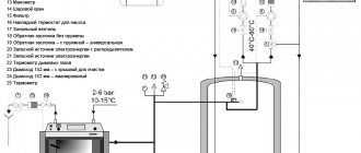
To control the flow and temperature of the coolant, an automatic thermal mixing device is used:
The device is also equipped with a check valve, an emergency automatic natural circulation valve (in case of a power outage), a built-in thermal fan and fitting.
The operating principle of the device is as follows. When the coolant reaches a certain temperature (780C), the thermal valve opens the water supply from the storage tank. The temperature is maintained at a given level by regulating the cross-section of the return passage from the central heating system to the bypass channel.
Connection diagram of a solid fuel boiler to a dual-purpose heat accumulator:
1. Security group; 2. Thermal storage tank; 3. Thermal mixer; 4. Membrane type expansion tank; 5. System make-up valve; 6. Heating system circulation pump; 7. Radiators; 8. Three-way mixing valve; 9. Check valve; 10. Circulation pump for the DHW system.
Connecting a heat accumulator and a separate DHW boiler
The volume of the passive heating boiler of the DHW system depends on the number of consumers and the power of the equipment used. When piping pellet boilers, it is not recommended to use polypropylene materials and structures. The outlet temperature of the heat exchanger at peak loads often exceeds the operating parameters of pipes made of polymer materials.
Connecting a solid fuel boiler with a separate hot water boiler:
1. Boiler. 2. Group 3. safety. 4. Diaphragm expansion tank. 5. 6. Pump. 7. Three-way mixing valve. 8. System make-up valve. 9. Radiator. 10. Indirect heating DHW boiler. 11. Thermal storage tank.
Parallel connection of two heating boilers
In order to extend the service life and evenly distribute the resources used, users often connect two different types of heating sources into a single heat supply scheme. In this case, the main source of heat in winter is a solid fuel boiler. The electric boiler is turned on in emergency mode and in the summer months, when it is used to heat water.
Wiring diagram for a solid fuel heating boiler with a parallel electrical connection:
1. Pellet boiler. 2. Heating system safety group. 3. Alternative boiler (electric or gas). 4. Separator to remove air from the system. 5. Circulation pump. 6. Manual three-way mixing valve. 7. Dry running protection valve. 8. Expansion tank. 9. System water supply valve. 10. Heat accumulator. 11. Washbasin. 12. 13. DHW pump.
A heating system based on a pellet boiler is quite complex and requires careful configuration. Before performing installation work, carefully read the instructions provided by the manufacturing companies.
Calculation of the buffer tank for the boiler
The role of the heat accumulator in the general heating scheme is as follows: during normal operation of the boiler, accumulate thermal energy, and after the firebox dies out, release it to the radiators for a certain period of time. Structurally, a heat accumulator for a solid fuel boiler is an insulated water container of rated capacity. It can be installed both in the furnace room and in a separate room of the house. It makes no sense to place such a tank outside, since the water in it will cool much faster than inside the building.
Taking into account the availability of free space in the house, the calculation of a heat accumulator for a solid fuel boiler in practice is carried out as follows: the capacity of the tank is taken from the ratio of 25-50 liters of water per 1 kW of power required to heat the house . To more accurately calculate the buffer capacity for the boiler, it is assumed that the water in the tank will heat up to 90 ⁰C during operation of the boiler installation, and after turning off the latter, it will release heat and cool down to 50 ⁰C. For a temperature difference of 40 ⁰C, the heat output values for different tank volumes are presented in the table.
Table of heat output values for different tank volumes
| Thermal accumulator volume, m3 | 0.35 | 0.5 | 0.8 | 1 | 1.5 | 2 | 3 | 3.5 |
| The amount of heat released at a temperature difference of 40 ⁰С, kW/h | 20 | 30 | 45 | 58 | 85 | 115 | 170 | 210 |
Even if there is space in a building to install a large tank, it does not always make sense. It should be remembered that a large amount of water will need to be heated, then the power of the boiler itself should initially be 2 times greater than what is needed to heat the home. A tank that is too small will not perform its functions, as it will not be able to accumulate enough heat.
Heat accumulator calculation
A container for storing thermal energy can be either purchased ready-made or made independently. But a logical question arises: how big should the tank be? After all, a small tank will not give the desired effect, and too large will cost a pretty penny. The answer to this question will help you find the calculation of the heat accumulator, but first you need to determine the initial parameters for the calculations:
- heat loss of the house or its square footage;
- duration of inactivity of the main heat source.
Let us determine the capacity of the storage tank using the example of a standard house with an area of 100 m2, which requires an amount of heat of 10 kW to heat. Let’s assume that the boiler’s net downtime is 6 hours, and the average coolant temperature in the system is 60 °C. Logically, during the period of time while the heating unit is inactive, the battery should supply 10 kW to the system every hour, for a total of 10 x 6 = 60 kW. This is the amount of energy that should be accumulated.
Since the temperature in the tank should be as high as possible, for calculations we will take a value of 90 ° C; household boilers are still incapable of anything more. The required capacity of a heat accumulator, expressed in mass of water, is calculated as follows:
- Q is the amount of accumulated thermal energy, for us it is 60 kW;
- 0.0012 kW / kg ºС is the specific heat capacity of water, in more conventional units of measurement - 4.187 kJ / kg ºС;
- Δt – difference between the maximum temperature of the coolant in the tank and the heating system, ºС.
So, the water accumulator should hold 60 / 0.0012 (90 – 60) = 1667 kg of water, which is approximately 1.7 m3 in volume. But there is one point: the calculation is made at the lowest temperature outside, which happens infrequently, excluding the northern regions. In addition, after 6 hours, the water in the tank will only cool down to 60 ºС, which means that in the absence of cold weather, the battery can be “discharged” further until the temperature drops to 40 ºС. Hence the conclusion: for a house with an area of 100 m2, a storage tank with a volume of 1.5 m3 will be enough if the boiler is inactive for 6 hours.
Calculation of buffer capacity
The main criterion by which a buffer tank for a solid fuel boiler is selected is its volume, determined by calculation. Its value depends on the following factors:
- heat load on the heating system of a private house;
- heating boiler power;
- expected duration of operation without the help of a heat source.
Before calculating the capacity of the heat accumulator, you need to clarify all the listed points, starting with the average thermal power that the system consumes during the winter period. The maximum power should not be taken for calculation; this will lead to an increase in the size of the tank, and therefore to an increase in the cost of the product. It’s better to endure the inconvenience for a few days a year and load the firebox more often than to pay a crazy price for a large heat accumulator that will be used irrationally. And it will take up too much space.
Expert opinion. To provide thermal energy to a house with an area of 200 m2, a buffer tank containing 1 ton of coolant, which is a volume of 1 m3, is sufficient. The statement is true for the central part of the Russian Federation; in more southern or northern regions the situation will be different.
Normal operation of a heating system with a heat accumulator is impossible when the heat source has a small power reserve. In this case, it will never be possible to “charge” the battery completely, since the heat generator must simultaneously heat the house and load the tank. Remember that the selection of a solid fuel boiler for connection with a heat accumulator assumes a double thermal power reserve.
It is proposed to study the calculation algorithm using the example of a house with an area of 200 m² with a boiler downtime of 8 hours. It is assumed that the water in the tank will heat up to 90 °C, and during heating operation it will cool down to 40 °C. To heat such an area in the coldest time, you will need 20 kW of heat, and its average consumption will be about 10 kW/h. This means that the battery must accumulate 10 kW/h x 8 hours = 80 kW of energy. Next, the volume of the heat accumulator for a solid fuel boiler is calculated using the formula for the heat capacity of water:
m = Q / 1.163 x Δt, where:
- Q is the estimated amount of thermal energy that needs to be accumulated, W;
- m – mass of water in the tank, kg;
- Δt – the difference between the initial and final temperatures of the coolant in the tank is 90 – 40 = 50 °C;
- 163 W/kg °C or 4.187 kJ/kg °C – specific heat capacity of water.
For the example under consideration, the mass of water in the heat accumulator will be:
m = 80000 / 1.163 x 50 = 1375 kg or 1.4 m³.
As you can see, as a result of calculations, the dimensions of the buffer capacity are larger than what the expert recommends. The reason is simple: inaccurate initial data were taken for the calculation. In practice, especially when the house is well insulated, the average heat consumption per area of 200 m² will be less than 10 kW/h. Hence the conclusion: in order to correctly calculate the dimensions of a heat accumulator for a solid fuel boiler, it is necessary to use more accurate initial data on heat consumption.
For reference. There is also an enlarged calculation method, according to which for each kW of boiler thermal power there is 25 liters of heat accumulator volume.
Requirements for uninterruptible power supply
To find out which uninterrupted unit is suitable for a gas boiler, you need to determine in advance the requirements for the device. It will help to become familiar with the main indicators of a UPS that characterize the efficiency of its operation. Some of them:
- Active and apparent (including the reactive component) power, defined as the product of the supply voltage and the current in the load.
- Harmonic distortion coefficient, indicating the quality of the output voltage - the deviation of the sinusoid shape from the ideal form.
- The presence of an external battery allows the boiler to continue operating during a complete absence of mains power for several hours.
- Duration of operation in offline mode.
- Limits of permissible input voltage fluctuations in Volts.
The battery life depends to a large extent on its capacity.
When the operating conditions of the boiler equipment require long interruptions in the power supply, the possibility of connecting additional batteries should be provided. It is also desirable that the purchased device has the function of automatically monitoring the state of the electrical network and restoring normal power supply.
Connecting the heat accumulator to the heating system
As a general rule, the buffer tank is connected to the heating system in parallel to the heating boiler, therefore this circuit is also called a boiler piping circuit.
Let us present the usual diagram for connecting a heating unit to a heating system with a solid fuel heating boiler (to simplify the diagram, shut-off valves, automation and control devices and other equipment are not indicated on it).
Simplified wiring diagram for a heat accumulator
This diagram identifies the following elements:
- Heating boiler.
- Thermal accumulator.
- Heating devices (radiators).
- Circulation pump in the return line between the boiler and the heat exchanger.
- Circulation pump in the return line of the system between heating devices and heating equipment.
- Heat exchanger (coil) for hot water supply.
- Heat exchanger connected to an additional heat source.
One of the upper pipes of the tank (item 2) is connected to the boiler outlet (item 1), and the second is connected directly to the supply line of the heating system.
One of the lower pipes of the heat pump is connected to the boiler inlet, and a pump (item 4) is installed in the pipeline between them, ensuring the circulation of the working fluid in a circle from the boiler to the heat pump and vice versa.
The second lower pipe of the TA is connected to the return line of the heating system, in which a pump is also installed (item 5), which ensures the supply of heated coolant to the heating devices.
To ensure the functioning of the heating system in the event of a sudden power outage or circulation pumps failure, they are usually connected in parallel to the main line.
In systems with natural circulation of coolant, there are no circulation pumps (items 4 and 5). This significantly increases the inertia of the system, and at the same time makes it completely energy independent.
The heat exchanger for DHW (item 6) is located in the upper part of the heat exchanger.
The location of the additional heating heat exchanger (item 7) depends on the type of incoming heat source:
- for high-temperature sources (heating elements, gas or electric boiler) it is placed in the upper part of the buffer tank;
- for low-temperature ones (solar collector, heat pump) - in the lower part.
The heat exchangers indicated in the diagram are optional (items 6 and 7).
Where to put the circulation pump
In most schemes for piping a heat accumulator with a circulation pump, it is located in the return pipeline in front of the boiler. In the return - because the temperature is lower here, but you can also put it in the supply. Modern pumps are designed to pump coolant up to 110°C, so they do well there. Second point: when installed on the supply side, the pump will not create additional pressure on the heat exchanger, which will extend its service life.
In any case, when installing a circulation pump in the supply or return, there is no possibility of natural circulation. That is, if there is a power outage, the circulation will stop and the boiler will inevitably boil. To avoid this, install a four-way valve through which overheated water is discharged into the sewer system and recharged with cold water from the cold water supply system. This way, emergency cooling of the heat exchanger is organized and boiling of the coolant is prevented.
One way to avoid overheating of the coolant in a heating boiler
Please note that this scheme can only be implemented on steel or copper heat exchangers. With cast iron - you can't. If exposed to cold water, they may burst.
There is another way. It is more gentle on the heat exchanger (also suitable for cast iron) and requires less materials. You can make a connection between the boiler and the heat accumulator for heating so as to maintain natural circulation. In this case, when the power supply is turned off, the boiler will not boil - it will continue to heat the water in the container.
To maintain the natural circulation of the coolant, the pump is installed in a separate, specially created circuit. For the circuit to work, a large-section reed check valve is installed in the circuit.
This way natural circulation is maintained even in the absence of power supply
When the circulation pump is not working, it passes the coolant flow from the heat exchanger. When the circulation pump is operating, its pressure props up the valve and the coolant flows through the pump. There is a pipe running to the pump that is at least an inch in diameter. Only in this case can natural circulation be maintained.
Principle of operation
The essence of the device’s operation in relation to boiler equipment does not differ significantly from the principle of protecting other electrical devices.
It is expressed in the adoption of special measures to stabilize the voltage and the ability to maintain it at the required level for some time. For these purposes, a UPS is used for boilers with a connected external battery, the direct voltage from which is converted into alternating voltage through an electronic inverter. To smooth out voltage fluctuations in the network or protect against its short-term loss, the principle of double conversion is used, consisting of the following:
- The corrected AC voltage is supplied to a line filter, which smoothes out sharp fluctuations by limiting RF harmonics.
- It enters the diode bridge, which converts the alternating component into a constant one.
- If necessary, part of the rectified current is spent on the charging circuit of the standby battery, used in a situation where the voltage disappears for a long time.
- The main part of it goes to the inverter, in which the reverse conversion of the constant component into variable is carried out.
- The stabilized voltage thus obtained is suitable for powering a solid fuel or gas boiler.
Advantages and disadvantages of buffer tank
Buffer tank for boiler
The main advantages of a heating system with a heat accumulator include:
- the maximum possible increase in the efficiency of the solid fuel boiler and the entire system while simultaneously saving energy resources;
- ensuring protection of the boiler and other equipment from overheating;
- ease of use of the boiler, allowing it to be loaded at any time;
- automation of boiler operation through the use of temperature sensors;
- the ability to connect several different heat sources to the heater (for example, two boilers of different types), ensuring their integration into one circuit of the heating system;
- ensuring stable temperature in all rooms of the house;
- the ability to provide domestic hot water without the use of additional water heating devices.
The disadvantages of heat accumulators for heating systems include:
- increased inertia of the system (from the moment the boiler is ignited until the system reaches operating mode, much more time passes);
- the need to install the heat exchanger near the heating boiler, for which a separate room of the required area is required in the house;
- large dimensions and weight, making it difficult to transport and install;
- the fairly high cost of industrially produced heat pumps (in some cases, its price, depending on the parameters, may exceed the cost of the boiler itself).
An interesting solution: a heat accumulator in the interior of the house.
In the interior
Installation 1st floor Attic Basement Section
The use of a heat accumulator is economically beneficial not only for solid fuel boilers, but also for electric or gas heating systems.
In the case of an electric boiler. The TA turns on at full power at night, when electricity tariffs are much lower. During the day, when the boiler is turned off, the premises are heated using the heat accumulated during the night.
For gas boilers, savings are achieved through the alternate use of the boiler itself and the heat exchanger. At the same time, the gas burner turns on much less frequently, which ensures lower gas consumption.
It is undesirable to install a heat accumulator in heating systems where rapid and or short-term heating of the room is required, since this will be hampered by the increased inertia of the system.
3 comments
Instead of the heat accumulators indicated in the article, storage water heaters with a capacity of 200 liters or more, connected in parallel, can be successfully used. Heat accumulators are connected to the heating boiler after normal heating of the house and (or) the threat of overheating of the boiler. This is much cheaper than the options offered. In addition, heating elements of water heaters can be used when the boiler is not operating, for example, at night. This is beneficial with a multi-tariff meter. The only thing is that when using ethylene or propylene glycol as a coolant, the magnesium rod installed to soften the water must be removed from water heaters. This system has been working for me for four years, allowing me to fire my solid fuel boiler once a day even in winter. In severe frosts (from -27) twice a day. The heat accumulator is served by three storage water heaters with a capacity of 200 liters each. Each water heater cost me 9700.
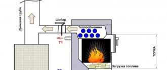
Heating device with TA
A thermal accumulator (TA) for heating boilers is an integral part of the heating system that works to increase the time interval between cycles of fuel supply to the combustion chamber. Structurally, it is a sealed, insulated container of large volume, filled with coolant from the heating system, which constantly circulates along the circuit(s). Traditional liquids are used as a coolant - distilled water, antifreeze, water-glycol solutions.
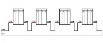
The only feature that must be taken into account when deciding whether to include it in the TA scheme is the volume of heated premises. The smaller it is, the less sense there is in installing a heat accumulator - the power of the boiler and heating devices (radiators, batteries) is quite enough to heat small rooms. How heating with a heat accumulator works - simplified connection diagram:
- The heat accumulator is connected to the gap between the boiler and the pipework, that is, the liquid heated in the boiler is immediately directed into the container;
- From the battery, hot liquid flows into the heating devices through piping;
- By return flow, the liquid is again sent to the accumulator, and from it to the boiler for a new heating cycle.
Schematic diagram of the operation of heating with a heat accumulator.
The supply and return flows must be constantly mixed - this is a condition for the effective operation of the heat accumulator. But the heated coolant rises up, and the cooled coolant goes down, so the difficulty of ensuring the system’s operability lies in creating conditions under which a certain volume of hot liquid sinks to the bottom of the accumulator to heat the cooled liquid from the return. A charged battery is a reservoir in which the entire volume of coolant has the same temperature.
After the combustion of the next portion of solid fuel, the boiler stops heating the water and the heating unit begins to work. The hot coolant continues to move in the system, giving off heat and cooling in the batteries. The circulation will continue until the coolant has cooled completely, or a new portion of firewood or coal is loaded into the boiler.
If there is an automation system, critical cooling of the coolant is not allowed, since the supply of solid fuel in a heating system with a solid fuel boiler is controlled by temperature sensors: when a certain value is reached, meaning that the boiler has stopped supporting combustion, the sensor sends a signal to the actuator system, which opens the fuel supply valve – coal, pellets or peat.
Automatic loading of fuel into a solid fuel boiler
Disadvantages of operating a heating system with a heat accumulator for country and garden houses with seasonal residence:
- Rooms take longer to warm up;
- Due to the small size of the heating element, the volume of the heating circuit increases, so the cheapest coolant for such systems is water. Antifreeze and other synthetic fluids will be too expensive.
But every time you arrive, refilling the system with water is a troublesome task, and if you go to the dacha two or three times a month, it’s simply pointless. Therefore, additional steel spiral pipes are built into the heating unit, acting as heating circuits. The coolant flowing through the spirals does not come into contact with the coolant in the heat exchanger, but is a separate and autonomous heating or hot water circuit. By implementing such a simple technique, you can achieve universal use of any boiler, even the simplest single-circuit one. Moreover, the efficiency of such equipment will be used to the maximum.
Heat accumulator with a spiral circuit
The role of such passive spirals can also be played by active elements - electric heating elements, which can be connected to the electrical network or be autonomous - powered by solar energy (solar batteries). This method of heating coolant or hot water is considered auxiliary.
Connection professional advice
In order to correctly and most efficiently implement a private heating system based on any solid fuel boiler, you can connect the heat accumulator using several methods. They are quite common among professional craftsmen, but you can learn this on your own, since there is nothing complicated or supernatural in these schemes.
Advice! Consider the fact that the cost of work directly depends on the basic principle of constructing a system for constant circulation of fuel in the boiler.
Heat accumulator connection diagram
With liquid mixing
The diagram for connecting a heat accumulator to a common type of solid fuel boiler is extremely clear. It is easily and accessiblely used in the piping of constant heating systems, which are based on the circulation of a simple gravitational type of fuel in the boiler. In this situation, this happens:
- When the set volume of water is heated in the heat exchanger of the device, its circulation begins throughout the entire installed pipeline system, which passes through the boiler valve.
- When the temperature set by the user is reached, the built-in valve actively begins to work and accordingly maintain the preset value, gradually mixing only cold water from the boiler itself.
- At this moment, hot water from the installed unit is poured into the tank - this is how the heat accumulator is charged.
- Over the entire period of time, which can only be determined by the boiler tank, the fuel is completely burned out.
- The reverse process begins, which consists of supplying water to small radiators. Temperature stability is maintained all the time.
- When the direct source of the required heat cannot maintain stable heating of water in the heat accumulator tank, the installed valve is quickly and reliably closed, and the system instantly returns to its original state.
If there is no power supply or the circulation pump fails, the boiler immediately goes into a special buffer mode, which allows the entire system to operate only on the check valve.
Connecting a heat accumulator to a solid fuel boiler
The collected water, which has been heated up to this point in the boiler itself, then actively flows into the installed tank. Then it goes to several heating radiators. This continuous process ensures that the water heats up smoothly and high temperatures drop gently.
Advice! In order for the heating circuit to function at its best, the heat accumulator must be mounted high enough so that there is no contact with the heating radiators.
Use of heat accumulators for solid fuel boilers
For boilers of this type, the heating scheme with a heat accumulator provides for an operating mode in which the fuel can, if possible, burn without any residue, and the power of the equipment, as well as its efficiency, will be maximum.
In order to regulate the power of the equipment, you can limit the air supply to the combustion chamber. The connection diagram of a heat accumulator to a solid fuel boiler provides for such a system in which:
- the heat produced by the boiler operating at maximum power is sent directly to the water tank to heat it;
- after complete combustion of the fuel, the coolant does not stop circulating through the system from the storage tank to the radiators, gradually taking away thermal energy from it.