Classic fan coil connection diagrams
In domestic and industrial air conditioning systems, fan coil units are installed in groups, and the system can use both the same type of equipment and devices of different designs. Depending on the configuration of the fan coil units and the features of the air conditioning system, the equipment connection diagrams may vary dramatically.
Fig. 3. Connection diagram for fan coil units with the same hydraulic resistance, located at different levels.
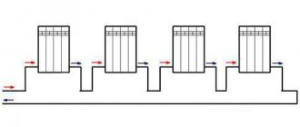
Fig. 4. Connection diagram for fan coil units with the same hydraulic resistance, located on the same level
Fig. 5. Connection diagram for fan coil units with different hydraulic resistance, located at different levels
Fig. 6. Connection diagram for fan coil units with different hydraulic resistance, located on the same level
Installation of the unit at the designated point is carried out in several stages. Typically, all rough work (installation of the housing, piping, drainage, etc.) is performed during the process of repair and construction work. Upon completion of the interior decoration of the premises, all that remains is to install the front grilles and configure the automation.
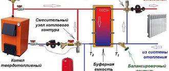
Fan coil piping in Moscow. Strapping scheme
Fan coil piping. Strapping scheme
The performance of any climate circuit depends on a number of specific factors. Fan coil units are no exception. When designing and installing them, special attention should be paid to the strapping. Its proper arrangement ensures trouble-free operation of the equipment in an automated mode and allows you to achieve optimal climatic conditions in the shortest possible time.
Note. High-quality piping also affects the efficiency of identifying problems in the operation of equipment.
Two-pipe system piping format
A system of this format assumes the presence of a fan coil unit with only one heat exchange circuit. This option is the most popular and widespread today. Here, one pipe is connected to the fan coil unit to supply cold water, and the second is responsible for supplying it to the chiller. In winter, such a system makes it possible to heat the room. To do this, connect the pipes to an individual or central heat supply circuit. In this case, no water comes from the chiller. In the summer, a valve is responsible for blocking water from the boiler, and the fan coil operates using water coming from the chiller. In this situation, mixing of coolant and refrigerant within the main line is permissible.
Remember. The cost of such a system is more affordable compared to a four-pipe analogue. It's all about connecting the fan coil only to the chiller. In the second case, we are talking about connecting it with several external devices at the same time.
Piping a four-pipe fan coil
Such a circuit provides for the presence of fan coil units with two heat exchange lines. Here both heat exchangers are connected to pipelines for hot and cold coolant. And each circuit is equipped with an individual valve for piping the fan coil unit. The valves are controlled using a special remote control. The use of such a system is relevant when there is a need to avoid mixing the coolant with the refrigerant.
Important! The use of four-pipe fan coils is possible all year round. In this case, heating and air conditioning of different rooms can be carried out simultaneously. Such loads require special attention to all elements of the harness. We are talking about the tightness of pipelines, their effective thermal insulation, the presence of the required valves and the necessary sensors.
Fan coil housing installation
For each fan coil model there is only one possible installation method:
- Units for floor mounting (console) are installed on special racks. The cabinet is secured to the wall with flat head screws.
- Wall-mounted vertical installation involves drilling technical holes according to the template supplied with the equipment. Dowels are inserted into the holes, then screws onto which the fan coil unit is hung.
- For ceiling mounting, the unit is almost always installed behind a suspended ceiling. In order for the decorative panel to protrude flush with the suspended structure, the housing is attached to the ceiling using anchor bolts and mounting studs or similar bolts and brackets.
Installation features
Taking into account the complexity of fan coil-chiller systems, its installation and configuration should be carried out by highly professional specialists. Only they will be able to perform high-quality installation of fan coil units by performing competent:
- installation of the unit in the place where its operation will be most efficient;
- assembly of piping units, installing the necessary taps, valves, temperature and pressure control devices;
- laying and thermal insulation of pipes;
- installation of a condensate drainage system;
- work on connecting devices to the electrical network;
- pressure testing the system and checking its tightness;
- supply of carrier (water).
They will also make all the necessary calculations before starting work, taking into account what functional load a particular fan coil unit will perform, as well as the characteristics of each room in the structure.
Thus, you were able to see not only that fan coil-chiller systems are very efficient, economical and reliable, but also that they require complex installation and commissioning operations. And for this it is necessary to attract employees of organizations specializing in the creation of such turnkey systems.
Assembling the harness
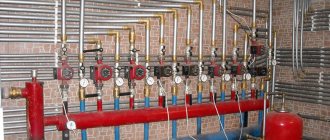
The fan coil unit is connected in accordance with the requirements of SP 73.13330.2012 and R NOSTROY 2.15.1-2011. The hydraulic circuit uses various options for manual and automatic shut-off valves (taps, valves), filters, control devices (pressure gauges, thermometers), and drain fittings.
When connecting the circuit, it is important to use pipelines of the same diameter (or slightly larger) as the fan coil fittings. In order for equipment to operate without interruption in the future, it is important to ensure the required level of tightness of all connections. Fractures of the water circuit and drainage pipes are unacceptable.
In practice, the two-pipe piping scheme, presented in several versions, is most often used.
Fig. 7. Fan coil piping diagram using a 2-way valve
Fig. 8. Fan coil piping diagram using a 3-way valve
Installation of duct type fan coils
In one of the elite residential complexes in Moscow, a central air conditioning system based on a chiller-fan coil system has been implemented: the external unit is placed on the roof, pipes have been installed to supply coolant (ethylene glycol) to each apartment.
Our task is to create a ducted air conditioning system for the apartment and a ventilation system. Duct fan coil units are not much different from ducted air conditioners and are distinguished by the fact that they provide the ability to maintain temperature while being invisible due to the air supply through channels with outlet through diffusers and slotted grilles.
A short video of the site for the installation of a ventilation and air conditioning system using ducted fan coils.
Example of completion of work
Installation of a duct system
Laying thermal insulation of pipelines
The surface of the water circuit pipes should not come into contact with the room air - this risks high heat loss and the formation of condensation on the pipes. Considering that the entire hydraulic circuit is hidden behind building structures, the appearance of dampness (and consequently mold) should be prevented in advance by insulating the pipelines. At an average room temperature of +300C and a humidity of 80%, the insulation layer must be at least 2 cm. Otherwise, condensation may appear on the surface of the insulating winding.
Installation of ducted fan coil units
Step #1
This is what a duct-type fan coil looks like in the original: without any adapters, insulation and other “attachments”.
Step #2
Preparing a ducted fan coil for installation.
Step #3
Preparing the fan coil unit for installation
Step #4
The equipment is finally prepared for installation. All riveted joints are sealed and covered with insulation.
Step #5
Adapter assembly. Final finishing, as well as pasting with thermal insulation, is carried out directly on site before installation.
Step #6
Installation of air ducts for ventilation and air conditioning systems.
Step #7
Rigid tin air ducts insulated. The expensive consumable material K-Flex is used; foam rubber has exceptional sound insulation and heat insulation properties. Everything should work at 5+! Two hoses are connected to one fan coil unit through adapters for air supply and two for distribution throughout the room.
Step #8
Duct fan coil unit with piping and air ducts. Everything will be hidden under the finished ceiling; after the repair and installation is completed, only decorative grilles and diffusers will remain.
Step #9
Duct fan coils
Step #10
Air ducts for ducted fan coil
Step #11
Duct fan coil adapter
Step #12
A slot diffuser under a decorative grille, through which cooled or heated air will be distributed in the future.
The first stage will soon come to an end and we will remove the teams from the site. Before the client calls for the completion of work, during which the installation of decorative grilles and diffusers will be carried out, work has been carried out to set up the automation and control system.
We wish our client (whom, by the way, the whole of Russia knows by sight) a successful and speedy completion of the repair and thank you for the trust you have placed in us!
Creation of a drainage system
Special technical channels are used to drain condensate formed during the cooling process. Throughout the entire drainage path, a continuous slope with a ratio of 1/100 must be maintained, and the possibility of the formation of stagnant zones for condensate must be excluded.
The resulting condensate first accumulates in a tray located under the heat exchanger, from where it flows through a pipe in the side wall. The drainage pipeline and the outlet pipe of the unit must be tightly connected using a clamp to avoid leaks and air pockets. It is recommended to install a water seal in the tray before starting.
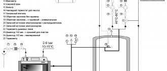
Fig. 9. Basic design of the fan coil drainage unit
System testing
Before you start operating the fan coil system, you need to carry out a number of test activities. This is necessary in order to check the functionality of all equipment elements.
Crimping
First, you need to rinse all parts of the water supply pipeline with water. Next, the entire system is filled with water and the tightness of all joints of the system is checked. The next step is to create the appropriate pressure using a hydraulic pump. The system is under increased pressure for 5 minutes. This will help find leaks that were not detected during the initial visual inspection.
The success of the tests at this stage is indicated by the fact that the system did not leak and the created pressure did not decrease.
Starting water
After filling the water circuit with liquid, it is possible that air will remain in the system. Its removal is carried out during operation of the equipment and takes a couple of hours. These actions are carried out using a manual air bleed valve.
It is also mandatory to check the drainage of the fan coil unit. To do this, add a small amount of water to the condensate collection tank. The liquid should gradually drain through the drain tube. If this does not happen, you need to check the slope of the drain.
Nutrition
Connection to the electrical network is possible only when all sections of the equipment wiring have been checked. What you need to pay attention to:
After the final check of all mechanisms, a corresponding document is drawn up, and the fan coil units can be operated.
The condensate pump must be checked before connecting the device to the network
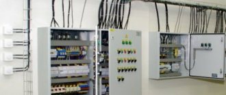
Electrical connection
- The unit must be grounded before making electrical connections.
- To connect the unit, you must use a cable with a cross-section recommended by the manufacturer.
- The fan coil unit must have a separate power source with rated voltage; The voltage value should be in the range of 90 ~ 110% of the rated voltage.
- It is recommended to connect the unit directly to the panel using all three conductors, including grounding.
- It is permissible to connect the equipment to a single-phase outlet network with a voltage of 230 V, a frequency of 50 Hz.
- The terminal box must be installed on the side opposite to the side where the water circuit is connected.
- It is necessary to exclude contact of the supply voltage wires and control wires, as well as contact of the wires with elements of the hydraulic circuit.