The charge controller is a very important component of the system in which solar panels create electric current. The device controls the charging and discharging of batteries. It is thanks to him that the batteries cannot be recharged and discharged so much that it will be impossible to restore their working condition.
You can make such controllers yourself.
Homemade controller: features, components
The device is designed to work with only one solar panel, which creates a current of no more than 4 A. The capacity of the battery, the charging of which is controlled by the controller, is 3,000 A*h.
To manufacture the controller, you need to prepare the following elements:
- 2 microcircuits: LM385-2.5 and TLC271 (is an operational amplifier);
- 3 capacitors: C1 and C2 are low-power, have 100n; C3 has a capacity of 1000u, designed for 16 V;
- 1 indicator LED (D1);
- 1 Schottky diode;
- 1 SB540 diode. Instead, you can use any diode, the main thing is that it can withstand the maximum current of the solar battery;
- 3 transistors: BUZ11 (Q1), BC548 (Q2), BC556 (Q3);
- 10 resistors (R1 – 1k5, R2 – 100, R3 – 68k, R4 and R5 – 10k, R6 – 220k, R7 – 100k, R8 – 92k, R9 – 10k, R10 – 92k). They can all be 5%. If you want greater accuracy, you can use 1% resistors.
How to choose a controller for a solar battery?
This is a very important device, which is quite difficult to choose correctly among the great variety. To take what you really need, adhere to the following data:
- Battery power. At the output, the total power should not be greater than the current indicator.
- Input voltage level. It should be 20% larger than U battery, which is produced by light-to-current converters.
Solar battery charge controllers are currently available in all varieties. It may have protection from bad weather conditions, heavy loads, short circuits, overheating, and even from improper activation. For example, this can happen when you confuse the polarity. As a result, you need to buy a device that will have several levels of protection.
How can some components be replaced?
Any of these elements can be replaced. When installing other circuits, you need to think about changing the capacitance of capacitor C2 and selecting the bias of transistor Q3.
Instead of a MOSFET transistor, you can install any other one. The element must have low open channel resistance. It is better not to replace the Schottky diode . You can install a regular diode, but it must be placed correctly.
Resistors R8, R10 are equal to 92 kOhm. This value is non-standard. Because of this, such resistors are difficult to find. Their full replacement can be two resistors with 82 and 10 kOhm. They must be turned on sequentially .
Controller connection methods
Before connecting, you must make sure that the voltage of the solar panels does not exceed the controller rating. If it is larger, you need to change the device to a more powerful one, capable of working with high current and voltage levels.
Before starting work, you must select a place for installing the controller with appropriate conditions - dry, clean, heated. There should be no contact with the sun's rays, and there should be no nearby mechanisms that create vibration.
PWM
The procedure for connecting PWM controllers consists of the following steps:
- connecting batteries to the corresponding terminals of the device. It is important to ensure correct polarity
- a fuse must be installed at the connection point of the positive wire
- Connect the wires from the solar panels to the corresponding contacts, observing the polarity
- turn on the signal lamp at the load output
Important! This sequence cannot be broken. If you connect the solar modules first, you can disable the solar charge controller, since it will have nowhere to send the received voltage.
In addition, it is not allowed to connect an inverter to the contacts intended for connection to the load. It can only be connected to the battery pack.
MPPT
The principle of connecting these controllers is no different from the above, but some additions may be required. For example, on powerful systems it is necessary to use a cable that can withstand a passing current density of at least 4 amperes per square millimeter of cross-section.
Before connecting, it is recommended to perform a simple calculation again (divide the maximum current value by 4 and add about 10-15% for the safety margin). This will ensure normal operation of the switching, eliminating heating and the risk of fire.
Before starting the connection, you must remove the fuses from the solar panels and battery pack. After connecting the controller to the batteries and solar modules, the ground loop and temperature sensor are connected. Check that all connections are correct, then reinstall the fuses and turn on the system.
The simplest controllers of the Off/On (or On/Off) type
Controllers of this type only work to start or stop battery charging when the charge drops or rises. They do not take into account additional operating conditions and do not determine the optimal mode, performing only the functions of a trigger configured to switch when the minimum and maximum values are reached.
Such controllers are currently out of production and have not been used for a long time, although they can still be found in some systems. The only advantage is the simplicity of the circuit , which makes the operation of the device reliable and stable. The connection is made by connecting the input and output wires to the batteries and solar panels, there is no additional switching.
Principle of operation
If there is no current from the solar battery, the controller is in sleep mode. It doesn't use a single watt from the battery. After sunlight hits the panel, electric current begins to flow to the controller. It should turn on. However, the indicator LED along with 2 weak transistors turns on only when the current voltage reaches 10 V.
Once this voltage is reached, current will flow through the Schottky diode to the battery . If the voltage rises to 14 V, amplifier U1 will start working, which will open the MOSFET transistor. As a result, the LED will go out and two low-power transistors will close. The battery will not charge. At this time, C2 will be discharged. On average this takes 3 seconds. After capacitor C2 discharges, the hysteresis of U1 will be overcome, the MOSFET will close, and the battery will begin to charge. Charging will continue until the voltage rises to the switching level.
Charging occurs periodically. Moreover, its duration depends on the charging current of the battery and how powerful the devices connected to it are. Charging continues until the voltage reaches 14 V.
The circuit turns on in a very short time. Its activation is influenced by the charging time of C2 with current, which limits transistor Q3. The current cannot be more than 40 mA.
How to connect a charge controller for solar panels?
This device can be located inside the inverter, or can also be used as a separate tool.
When thinking about connection, you should take into account the characteristics of all components of the power plant. For example, U should not be higher than what the controller can work with.
Installation must be done in a place where there will be no moisture. Below we present options for connecting two common types of controllers for a solar battery.
MPPT connection
This is quite a powerful device and connects in a certain way. At the ends of the wires with which it is connected there are copper lugs with clamps. Negative marks attached to the controller must be equipped with adapters, fuses and switches. Such a solution will prevent loss of energy and make the solar power plant safer. The voltage on the solar panels must match the voltage of the controller.
Before connecting the mppt device to the circuit, switch the switches on the contacts to the “Off” position and remove the fuses. All this is done according to the following algorithm:
- Connect the battery and controller seals.
- Attach the solar panels to the controller.
- Provide grounding.
- Install a sensor monitoring the temperature level on the control device.
When performing this procedure, ensure that the polarity of the contacts is correct. When everything is done, turn the switch to the “ON” position and insert the fuses. Correct operation will be noticeable if charge information is displayed on the controller display.
Connecting the solar panel to the PWM controller
To do this, follow a simple connection algorithm:
- Connect the battery cables to the pwm controller terminals.
- The wire with polarity “+” must have a fuse for protection.
- Connect the wires from the solar panel to the solar battery charge controller.
- Connect a 12 volt light bulb to the controller load terminals.
When connecting, observe the markings. Otherwise, the devices may break. The inverter should not be connected to the contacts of the control device. It should cling to the battery contacts.
Controller Michael Davis
This device is designed for more powerful solar panels. It does an excellent job of regulating the charging of batteries with the current produced by the wind generator. Since the device has a fairly simple structure, you can make it yourself.
There are two variants of this controller . The first one is old and imperfect. The second is simpler and more effective. Its diagram is in the figure:
To create it you need to prepare:
- 2 regulators: 7805 (K142EN5A) (IC1) and NE555 (IC1);
- 2 standard buttons (РВ1 and РВ2);
- 2 LED bulbs. One is green, the other is yellow;
- 1 12 V automotive relay (RLY1). It is advisable to select a relay that allows you to switch currents of 30-40 A;
- 1 diode 1N4001. You can take any similar one;
- 2 tuning resistors 10K. In the diagram they are designated as R1 and R2. It is better if they are multi-turn. It is allowed to take resistors whose adjustment interval is 0-100K. However, 10K elements provide better adjustment;
- 3 resistors 1K Ohm 1/8 W 10% (labeled R3-R5);
- 1 resistor 330 Ohm (R6);
- 1 resistor 100 Ohm (R7);
- 2 transistors 2N2222 and IRF540. Designated as Q1 and Q2 respectively. Instead of the first transistor, you can take 2N3904, NTE123 or any other one, it has a bipolar NPN structure and similar characteristics. You can do the same with the second transistor;
- 2 capacitors 0.33uF and 0.1uF. Both are designed for 35 V. The type of capacitor can be any.
All these elements are placed on the board and soldered. After which the initial adjustment of the circuit . It consists of setting voltage levels at control points TP1 and TP2 . The voltage on the first should be 1.667 V, on the second – 3.333 V. These levels are set by setting the buttons. Also, a fuse for the appropriate current should be installed on each power circuit.
A short introduction. 1- Anticipating in advance statements and “advice” such as “why is this needed”, “It’s easier to lay the cable”, “buy ready-made and don’t worry”, I’ll say right away that this whole project is of academic interest rather than economic. 2 — You can read this “opus” “diagonally,” that is, go directly to the practical parts. Namely, “Converting a UPS into a 220 Volt inverter” and “Independent production of a PWM battery charge controller.” The thing is, I didn't want to ruin the integrity of the story, and I was interested!
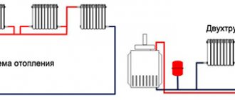
Summer. The summer season is in full swing. All sorts of planting and major work have been done, now it’s just barbecue, rest and waiting for the harvest :). And my next attempt to combine business with pleasure. Namely, I wanted to try my hand at organizing the power supply to the second floor of the dacha (as of yet it is not there in principle, only with the help of an extension cord). After googling a little and reading the relevant resources, I outlined the “cubes” of the future project. Typical block diagram of the organization of “solar power supply”.
“Large checkered” - it’s simple! It is very convenient that any such cube can be replaced/upgraded in the future. For example, it will be possible to add another battery in parallel. Or install a solar panel if this power is not enough, and so on. In short, I decided to try it.
As they say, “For a big ship, a long voyage,” and “For a serious project, scientific and careful calculation!” 
Energy justification.
This is what I plan to use on the second floor of the dacha:
Sit for an hour or two with a laptop (80 watts), perhaps a router with a 3G modem, a couple of LED light bulbs (10..20 watts), a small TV (80..100 watts), a small soldering iron sometimes (25..35 watts), and so on. recharge your phone (tablet) (let it be another 10 watts). This all, as a rule, does not happen at the same time and for a couple of hours. We think 250 watts. The operating hour of all energy consumers is 0.25 kWh. (Here you can see examples of calculations: ru.wikipedia.org/wiki/%D0%9A%D0%B8%D0%BB%D0%BE%D0%B2%D0%B0%D1%82%D1%82-%D1 %87%D0%B0%D1%81) A typical, average car battery (55 Ah) has an energy reserve of 55*12=660 Watts. That is, with a rough calculation (even taking into account all sorts of losses during conversion), it should be enough for more than two hours (660/250 = 2.6) to operate all the planned electrical equipment turned on at the same time. It is also important that I will only use this on weekends - 2 days, and the battery will be charged for 5 days. Even taking into account that the weather here (in the Republic of Belarus) is not always sunny, a 50-watt solar panel (3 Amps) should charge the battery in 12 hours of GREAT sunny weather. This is a theory. Practice says that you need to throw on more. Okay, okay, let it charge for 20 hours. I really, really hope that this week will add up to 20 clear/sunny hours.
Naturally, all solar power supply units can be purchased. ( And in general, you can buy almost everything in this world. Well, except, probably, the money itself. But then life is generally boring
).
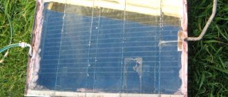
So, let's try to do everything on our own as much as possible. So, Solar panel (hereinafter according to the SP
) and the battery (hereinafter referred to as
battery
) - nothing can be done... You won’t be able to save.
These components will have to be purchased. (A small correction about the joint venture. Initially, I thought of assembling it myself, from separate sockets (0.5 volts at a cost of about 3 USD). It turned out that at a minimum I would need about 30 sockets. Plus steady hands and a lot of patience and accuracy. But , fortunately, I found people selling ready-made panels for outdoor use and not very expensive - 80 USD. Its parameters: 20 volts no-load and a short-circuit current of about 3 Amps. Power 50 Watts. Exactly, what I need .Ordered while I'm waiting
).
But the inverter and controller are all in our hands 
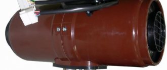
INVERTER.
To convert electricity from a 12 volt battery to 220 volt alternating voltage, inverters are usually used.
Naturally, a car inverter is ideal for this application. But... Ivanovich’s favorite principle: “use what is at hand and don’t look for anything else.” Let's try to use a UPS as an inverter. He's a trouble-free guy. I think in every office there are a couple of working UPSs (uninterruptible power supply) with drained batteries. So we’ll try to stir things up with him. The Internet is simply teeming with material about this option. Fortunately, I even had uninterruptible power supply systems to choose from. However, I settled on the Vivaldi 800VA. I'll try to explain why. What is also important: 1. it turned out to be the most powerful (800 watts) 2. it turns on just a button with two states (not touch or intelligent, like you need to press and hold for a couple of seconds) 3. it turns off depending on the state of the battery (and not according to a given time interval). What is also important: it itself controls the degree of battery discharge. 4. It has two regular sockets on the back. 5. it turned out to be fully working and was in a metal case
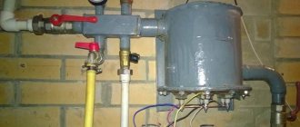
As a modification, I did:
- Installed a small adapter board with a 25 amp fuse - Removed the power cord. Instead, I brought out powerful wires (cross section 4 mm2) with terminals for connecting the battery. — Removed the annoying buzzer-buzzer — Reinforced the hottest radiator with additional copper — Installed a forced fan and drilled holes in the case for it
Conducted “sea trials”. An ordinary PC with a CRT monitor (yes, I found such a monitor) worked wonderfully for 2 hours. Quite a good result.
Well, the main part of my opus: CHARGE CONTROLLER.
A little theory. For general understanding and development. The charge controller is an important element in the intended power supply system. It maintains the required voltage level on the batteries, preventing them from being completely discharged or overcharged. There are several types of controllers:
After googling, I found two interesting options for the MPPT controller: 1) www.256.co.uk/?p=1158 2) duino4projects.com/arduino-peak-power-tracker-solar-charger/ But to implement the MPPT option, you need to control the current . I didn’t have anything suitable for this at hand. For the future, I had to order the MAX4173 chip from China.
Well then. Let's try our hand at making a PWM controller. I took as a basis the creation of a certain comrade from distant India. Everything is very well described and explained (though not in Russian). Read here: www.instructables.com/id/ARDUINO-SOLAR-CHARGE-CONTROLLER-PWM/
My “wants”: - shield board (standard size) - the board should be single-sided - the ability to quickly connect wires (i.e., terminal blocks) - display useful information on a two-line LCD 16x2 - make the LCD remote (in case you need to place it in a case) and switchable (on the connectors) - additional LED indication (to understand what is happening from afar) - autonomous operation of the device (i.e., without additional batteries) - safe operation of the device without supervision
A controller circuit is actually a compilation of pieces from different circuits. In its final form it looks like this.
Please note that the diagram does not include a load control unit. The fact is that the homemade “INVERTER” I made controls this moment itself.
As they say: “A good thought comes later.” Honestly, I think it would be more correct to make three separate lines from the battery (5 Volts, 12 Volts and 220 Volts) and still control the voltage on the battery, in order to avoid severe battery discharge . For example, why connect the power supply of the same router to a 220 Volt line, if it is more logical to connect it directly to the 5 Volt line. But I will try to take this option into account in the next craft. Hmm, if I don't lose interest.
Conventionally, this scheme can be divided into the following nodes:
Power supply unit. In the picture under number 5. A little bit of poetry. At work, many colleagues have acquired video recorders. And to connect to the on-board network, many abandoned the standard connection to the cigarette lighter. In this regard, our amateur radio fraternity has studied the issue of DC-DC converters quite closely. For these purposes, wonderful STEP-DOWN converters LM2576 were received from China in quite large quantities. Below is a snippet from the datasheet:
Agree that it would be a sin to waste the useful developments and microcircuits obtained in this way :). So, to power the Arduino in offline mode, I placed such a converter on the shield. It will be powered (through diodes) both from the joint venture and from the battery (in the dark).
What does this connection give us? Let the Anode of the first diode be connected to the battery (Ab), the anode of the second diode is connected to the SP (Asp), The cathodes are connected together and connected to the converter (K).
We have in the worst case: Aakb = 14V, Asp = 18V. The drop across the diode is, in the worst case, 1V, then at the common cathode there will be K = 18 - 1 = 17V. And, note, on Aakb = 14V, i.e. The diode is blocked by reverse voltage. Therefore, the current consumed by the stabilizer will flow from the joint venture (some amperes), and through the battery diode there will only be a reverse leakage current (it will be in the battery, like a charger) of several microamps, i.e. ZERO. Current will be consumed from both sources - the battery and the joint venture - only when their voltages are approximately equal. When the voltage at the joint venture drops below the voltage at the battery by about 0.7-1V, current will be consumed only from the battery.
There were slight doubts when choosing a converter voltage of 5 volts or 9. However, having decided that double conversion (the Arduino itself has a linear stabilizer) was ineffective, I opted for the 5-volt option.
Voltage control on the battery and on the joint venture. (Nodes No. 1 and 3, respectively) We take it with a reserve, the maximum voltage at the solar panel terminals is 25 volts, at the battery - 15 volts. Naturally, applying such voltages directly to Arduino is like death. Let's use an on-line calculator for a voltage divider (aka Voltage Divider
).
For those who are lazy (or don’t have the Internet :)), the calculation is carried out using the formula Vout=(Ra*Vin)/(Ra+Rb). In order not to “produce the nomenclature”, let’s take the resistor Ra 100 kOm. We get the following values For the joint venture: Input Voltage=25V Ra=100kOm Output Voltage=4.5V => Rb=22 kOm
For the battery: Input Voltage=15V Ra=100kOm Output Voltage=4.5V => Rb=42 kOm (I have it on hand was at 47 kOm)
To convert the “parrot” value at the ADC input into real volts, we had to calculate the necessary coefficients.
Status indication: two LEDs and LCD display. LEDs are nothing new. And connecting the LCD is “tune to tune” in accordance with the description on the official resource
The display itself is made remote and is connected to the shield with two cables: power and signal line.
PWM controller (Node No. 2). You can read more about PWM here arduino.cc/en/Tutorial/PWM or here I brazenly licked this node from an Indian. (No, of course, I honestly tried to replace the “field switch” with an n-channel one (they are more common and have less resistance when open). But, for it to be fully open, it is necessary to provide a positive potential (usually about 10 volts) between Gate and Source. Let me remind you that the Source in our circuit is connected to the “+" battery. There is a way out of this situation: the so-called Charge pump. But I didn’t want to complicate the circuit at that moment. Moreover, I plan to manufacture MPPT
controller).
Typically PWM controllers operate at a frequency of 50/100 Hertz. And Arduino has a default PWM on the 6th pin with a frequency of 976.5625 Hertz. In short, to change the PWM frequency, simply change the prescaler value to 1024 (instead of 64). TCCR0B = TCCR0B & 0b11111000 | 0x05; // prescaling 1024
And we get something around 61 Hertz. Let it be for now. Naturally, in this case the delay() functions and the like stop working correctly. Fortunately, this is not critical in this sketch.
For protection purposes, a 3 Ampere fuse is additionally installed on the board. ( Although, it would be more convenient to install it in the gap of the connecting wires
).
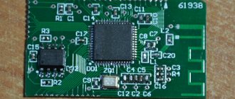
So, the printed circuit board:
Next, the classic chain: LOOT - HIT - TIN - SOLDER... Phew, Done. The finished controller looks something like this:
Reverse side (fuse for the power supply circuit from the converter (just in case of fire) and SMD diode)
Side view with a radiator installed on the field van:
Purpose of nodes, jumpers and connectors on the board
Jumper No. 3 - powering the Arduino from the SP and battery ( when using an external power supply or battery, the jumper must be removed
) No. 2 - converter operation indicator (can be disabled by jumper No. 1) No. 4 - LCD display contrast adjustment No. 5 - voltage dividers No. 6 - LED indicators of battery charge and status
To debug the system, I used a “half-dead” battery from a car (one colleague just bought a new one and gave the old one for experiments) and a 15 Volt (3 Ampere) power supply (since I don’t have a real solar panel yet).
Now let's move on to the software part.
I found algorithms for the “correct” charge on the forum arduino.ru/forum/proekty/pwm-kontreller-zaryada-na-attiny13?page=2 (Thanks to a friend with the nickname HWman, who was not lazy and painted each stage of the charge for me).
I decided to highlight five states in which the controller will be: - sleep mode. (SLEEP Mode)
.
The controller switches to this mode if the voltage from the SP is less than that required to charge the battery - CHARGE Mode
.
In this mode, all the current from the joint venture is given to the battery - EQUILIZING CHARGE mode (Balance Mode)
.
In this mode, by changing the PWM on the battery, the required voltage is maintained - SUPPORT CHARGE mode (Storage Mode)
.
In this mode, nothing happens, but the voltage on the battery is controlled. And at a certain value, it goes into charging mode. — Well, a small BONUS mode BATTERY RESTORATION (Refresh MODE)
. Here's what prompted this idea: Code implementation - Finite State Machine (aka, ). State graph (may be useful to someone):
For ease of perception, in the graph I used the same variables and constants as in the sketch.
And below is the sketch itself. It turned out to be not very voluminous, so I have given it here in full. For debugging, the output is left to the COM port. Naturally, useful criticism is welcome (Commented - to the maximum. I re-read it several times, I even figured it out myself
/* Simple Arduino Solar Charger Controller PWM Version with P-chanel MOSFET Ghost D. 2014 ============== ======================= And the final algorithm (thanks to HWman, from the ARDUINO.RU resource) will be like this: 1- PWM=255 while Uacb<14.4 2- How only Uaccb => 14.4 we set PWM at which Uaccb = 13.8 and keep the voltage at this level 3- If the PWM value is already very small (the charge current is already small), then we turn off the charge altogether and go into standby mode 4- as Uaccb<=12.7 - again from step 1 ==================================== Lead-Acid Batteries BOOST Voltage = 14.4 Volts NORMAL Voltage = 13.9 Volts STORAGE Voltage = 13.3 Volts */ #include LiquidCrystal lcd(12,11, 5, 4, 3, 2); int redLed=7; // LED - battery status - discharged int greenLed=8; // LED — charge state int pwmPin=6; // PWM output to MOSFET byte batPin=A0; // Analog port for connecting the divider with the battery byte solarPin=A1; // Analog port for connecting the divider with the battery float solar_volt =0; // Voltage on the solar panel float bat_volt=0; // Battery voltage float real_bat_volt=0; // Battery voltage at PWM=0 float start_bat_volt=0; //Voltage on the battery from which the REFRESH mode started byte curPWM=0; //Current PWM value int charged_percent =0; //Battery charge in % volatile boolean state = LOW; //for blinking the LED //long int timeWork=0; byte mode=0; //Operating mode of the “FINITE MACHINE” byte tmpCount=0; //counter, to be able to “spin” in the desired mode the required number of times char outMess[16]; //contents of the second line on the LCD //coefficient. divider for 100k/47k #define batDev 3.2 //coefficient. divider for 100k/22k #define solDev 5.8 //coefficient for converting data from the ADC into volts #define adc2volt 0.0047 //Battery voltage limits #define bat_full_volt 14.3 #define bat_balance_volt 13.8 #define bat_disch_volt 11.4 #define bat_storage_volt 12.7 #def ine bat_refresh_volt 9 / /Values for PWM #define pwm_charge 255 #define pwm_off 0 //step of changing the PWM value #define deltaPWM 10 //operating modes #define mode_charge 1 #define mode_balance 2 #define mode_storage 3 #define mode_sleep 4 #define mode_refresh 5 //—— —————————— // Reading the ADC value from the analog port // 250 measurements and calculating the average float readVolts(byte pin){ float tmpRead=0; for (int i=0;i<250;i++){ tmpRead+=analogRead(pin); } tmpRead=tmpRead/250; return(tmpRead*adc2volt); } //———————————— // read the voltage values on the SP and battery void read_U() { solar_volt=(readVolts(solarPin))*solDev; bat_volt=(readVolts(batPin))*batDev; } // read the voltage values on the battery at PWM=0 void read_U_bat_real() { analogWrite(pwmPin,0); real_bat_volt=(readVolts(batPin))*batDev; analogWrite(pwmPin,curPWM); } void setup() { TCCR0B = TCCR0B & 0b11111000 | 0x05; // Set PWM to 61.03 Hz (this will spoil the delay function) Serial.begin(9600); pinMode(pwmPin,OUTPUT); pinMode(redLed,OUTPUT); pinMode(greenLed,OUTPUT); digitalWrite(pwmPin,LOW); digitalWrite(redLed,LOW); digitalWrite(greenLed,LOW); lcd.begin(16,2); //lcd.clear(); // read_U(); mode=mode_sleep; } //end setup void loop() { switch (mode){ case (mode_charge): // CHARGE mode. PWM = 100% // In this mode, the red LED lights up, the green LED blinks // Until the voltage on the battery becomes more than 14.4 Volts // after that, switches to the EQUILIZING charge mode Serial.println(“======= ======="); Serial.println("MODE: Charge"); Serial.println("=============="); curPWM=pwm_charge; digitalWrite(redLed, HIGH); digitalWrite(greenLed,state); state = !state; if (bat_volt >= bat_full_volt) { mode=mode_balance; tmpCount=3; } sprintf(outMess, "%2d%% CHRG PWM=%3d",charged_percent, (map(curPWM,pwm_off,pwm_charge,0,100))); break; case (mode_balance): // EQUILIZING CHARGE mode. PWM = dynamic, to maintain the voltage on the battery = 13.8V // In this mode, the red and green LEDs blink // When the PWM value is less than 10 // switch to the MAINTENANCE charge mode // after changing the PWM, “to settle” the value do 3 passes Serial.println("=============="); Serial.print("MODE: Balance/Count: "); Serial.println(tmpCount); Serial.println("=============="); if (tmpCount==0) { if (bat_volt >= bat_balance_volt) { if (curPWM < deltaPWM) curPWM=pwm_off; if (curPWM != pwm_off) curPWM=curPWM-deltaPWM; Serial.print("- Decrise. "); Serial.println(curPWM); } if (bat_volt < bat_balance_volt) { if(curPWM > (pwm_charge-deltaPWM)) curPWM=pwm_charge; if(curPWM != pwm_charge) curPWM=curPWM+deltaPWM; Serial.print("+ Incrise. "); Serial.println(curPWM); } tmpCount=3; } digitalWrite(redLed, state); digitalWrite(greenLed,!state); state = !state; tmpCount=tmpCount-1; if (curPWM < 10) mode=mode_storage; sprintf(outMess, "Balance. PWM=%3d", (map(curPWM,pwm_off,pwm_charge,0,100))); break; case (mode_storage): // MAINTENANCE CHARGE mode. PWM = 0 // In this mode, the green LED is on, the red one is blinking // Until the voltage on the battery, the voltage becomes less than 12.7 Volts // switch to CHARGE mode Serial.println(“============ =="); Serial.println("MODE: Storage"); Serial.println("=============="); curPWM=pwm_off; if (bat_volt < bat_storage_volt) mode=mode_charge; digitalWrite(greenLed, HIGH); digitalWrite(redLed,state); state = !state; sprintf(outMess, "Storage Mode "); break; case (mode_sleep): // Sleep mode. PWM=0 // In this mode, the LEDs do not light up // When the voltage on the SP becomes greater than 14.4 Volts // switch to CHARGE mode sprintf(outMess, “Sleep Mode “); Serial.println("=============="); Serial.println("MODE: Sleep"); Serial.println("=============="); curPWM=pwm_off; digitalWrite(redLed, LOW); digitalWrite(greenLed,LOW); if ((solar_volt > bat_full_volt) && (bat_volt >= bat_disch_volt)) mode=mode_charge; if ((solar_volt > bat_full_volt) && (bat_volt < bat_disch_volt) && (bat_volt >= bat_refresh_volt)) { mode=mode_refresh; start_bat_volt=bat_volt; tmpCount=5; } break; case (mode_refresh): // BATTERY RECOVERY mode. PWM = PULSES, time ratio 4/1 // In this mode, the red and green LEDs flash // Exit this mode when the bat_disch_volt value on the battery is reached // or if, for example. on the battery will become (suddenly, the battery is turned off) < bat_refresh_volt Serial.println("=============="); Serial.println("MODE: Refresh"); Serial.println("=============="); lcd.setCursor(0,0); lcd.print(“- Refresh Mode -“); curPWM=pwm_charge; if (tmpCount==0) { tmpCount=5; curPWM=pwm_off; } tmpCount=tmpCount-1; lcd.setCursor(0,1); lcd.print("Ust:"); lcd.print(start_bat_volt,1); lcd.print("Uc:"); lcd.print(real_bat_volt,1); if (real_bat_volt >= bat_disch_volt) mode=mode_charge; digitalWrite(redLed, state); digitalWrite(greenLed,state); state = !state; break; } //end switch //General procedure for displaying information (still chaotic) read_U(); if (solar_volt < bat_full_volt) mode=mode_sleep; read_U_bat_real(); if (real_bat_volt
I worked on the code for several weeks... (vacation period and all that...). When testing with a power supply (instead of a solar panel, they won’t deliver) - everything is very nice and good.
During charging, the “field worker” heated up quite well. I measured his temperature (we have such a gadget for the tester) - and it reached 65 degrees Celsius. A bit much, but quite acceptable.
To be honest, I can’t yet say with confidence that the QUALITY of the charge is IDEAL! Time will tell Naturally, this code can be adapted to charge other batteries and implement other algorithms. As your heart desires!!!
For everyone who is interested and wants to repeat it, all the material is in one archive - HERE!!!