The principle of operation of the thermostat
A thermostat is a device that can respond to changes in temperature. Based on the type of action, a distinction is made between trigger-type thermostats, which turn off or turn on heating when a specified limit is reached, or smooth-action devices with the ability to fine-tune and accurately adjust, capable of controlling temperature changes in the range of fractions of a degree.
There are two types of thermostats:
- Mechanical. It is a device that uses the principle of expansion of gases when temperature changes, or bimetallic plates that change their shape when heated or cooled.
- Electronic. It consists of a main unit and a temperature sensor that sends signals about an increase or decrease in the set temperature in the system. Used in systems requiring high sensitivity and fine adjustment.
Mechanical devices do not allow for high precision settings. They are both a temperature sensor and an actuator, combined into a single unit. A bimetallic strip used in heating devices is a thermocouple made of two metals with different coefficients of thermal expansion.
The main purpose of the thermostat is to automatically maintain the required temperature
When heated, one of them becomes larger than the other, causing the plate to bend. The contacts installed on it open and stop heating. When cooled, the plate returns to its original shape, the contacts close again and heating resumes.
The chamber with the gas mixture is a sensitive element of the refrigerator thermostat or heating thermostat. When temperature changes, the volume of gas changes, which causes movement of the surface of the membrane connected to the lever of the contact group.
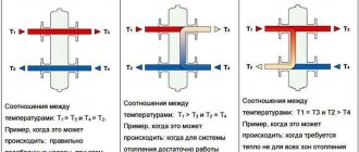
The thermostat for heating uses a chamber with a gas mixture that works according to Gay-Lussac's law - when the temperature changes, the volume of gas changes
Mechanical thermostats are reliable and provide stable operation, but the operating mode is adjusted with a large error, almost “by eye”. If fine tuning is necessary, providing adjustment within a few degrees (or even finer), electronic circuits are used. The temperature sensor for them is a thermistor, which is capable of distinguishing the smallest changes in the heating mode in the system. For electronic circuits, the situation is the opposite - the sensitivity of the sensor is too high and it is artificially coarsened, bringing it to the limits of reason. The principle of operation is a change in the resistance of the sensor caused by fluctuations in the temperature of the controlled environment. The circuit reacts to changes in signal parameters and increases/decreases heating in the system until another signal is received. The capabilities of electronic control units are much higher and allow you to obtain temperature settings of any accuracy. The sensitivity of such thermostats is even excessive, since heating and cooling are processes with high inertia, which slow down the reaction time to changing commands.
Simple water temperature controller
I propose the design of a simple water temperature regulator, which can be useful in a private home or at a summer cottage for heating water in a storage tank for domestic needs.
The device's regulation method is two-position. The heating elements are turned on and off using relay contacts. The device does not have a mains transformer; it is equipped with a control lamp, a potentiometer used to set the required temperature, and a temperature sensor, the role of which is played by a bipolar transistor.
Schematic diagram of the water temperature regulator:
Let's consider the operation of the circuit: an amplifier is assembled using transistors V1 and V2. The bias voltage at its input is regulated by variable resistor R2. The conductivity of transistor V1 depends on the temperature of its case. The higher the temperature, the greater the conductivity of the junction.
When power is supplied to the device and the temperature of the set value is set by resistor R2, the relay is activated and its contacts supply mains voltage to the heating elements. Water heating begins. When the set temperature is reached, the conductivity of transistor V1 changes, which leads to the closing of transistor V2 and the relay turning off. The water begins to cool. Having reached a certain temperature, the relay turns on again and the process repeats. The temperature of water fluctuations is no more than -5, +5 degrees. A voltage stabilizer is assembled on diodes D1-D3, which serves to prevent failure of the temperature setting, since when the relay is activated, the supply voltage drops slightly, which significantly affects the temperature setting value. C4 prevents interference from entering the amplifier input.
The device is powered by 220V AC mains. Through quenching capacitors C3, C4 and shunt diodes D5, D6, alternating voltage is supplied to the diode bridge and stabilized by a +24V zener diode. The length of the wire to the sensor is no more than 1 m. For longer lengths, shielded wire should be used. The board with the parts is mounted in a suitable housing; a potentiometer, indicator light and power switch are displayed on the front panel. The potentiometer scale must be calibrated using a standard thermometer from 20 to 100 degrees. If necessary, the control range can be shifted, narrowed or expanded using limiting resistors R1, R3.
ATTENTION! Be careful, the regulator is not galvanically isolated from the network, so do not touch its parts when it is operating. Sensor V1 must be insulated!
Regulator parts: transistor KT315 with any letter index. We will replace KT815 with KT817, KT805. A zener diode is suitable with a stabilization voltage of 20-30V. Diodes D1-D3 are almost any silicon low-frequency ones. D5, D6 for voltage not lower than 400V. Capacitors C3, C4 with a capacity of 4.7 to 5.6 microfarads for a voltage of at least 400V from energy-saving lamps, small-sized. Relay with a 24V coil and 5-10A contacts corresponding to the load power.
List of radioelements
| Designation | Type | Denomination | Quantity | Note | Shop | My notepad |
| V1 | Bipolar transistor | KT315B | 1 | Search in the Otron store | To notepad | |
| V2 | Bipolar transistor | KT815B | 1 | KT817, KT805 | Search in the Otron store | To notepad |
| D1-D3 | Diode | KD522A | 3 | Search in the Otron store | To notepad | |
| D4 | Diode | KD502 | 1 | Search in the Otron store | To notepad | |
| D4 | Zener diode | D816B | 1 | Search in the Otron store | To notepad | |
| D5, D6 | Rectifier diode | 1N4007 | 2 | Search in the Otron store | To notepad | |
| G1 | Diode bridge | DF06M | 1 | Search in the Otron store | To notepad | |
| C1 | Electrolytic capacitor | 47 µF | 1 | Search in the Otron store | To notepad | |
| C2 | Electrolytic capacitor | 470 µF 25 V | 1 | Search in the Otron store | To notepad | |
| C3, C4 | Electrolytic capacitor | 4.7 µF 400 V | 2 | Search in the Otron store | To notepad | |
| R1 | Resistor | 10 kOhm | 1 | Search in the Otron store | To notepad | |
| R2 | Variable resistor | 4.7 kOhm | 1 | Search in the Otron store | To notepad | |
| R3, R5 | Resistor | 6.8 kOhm | 2 | Search in the Otron store | To notepad | |
| R4 | Resistor | 3.3 kOhm | 1 | Search in the Otron store | To notepad | |
| R6 | Resistor | 120 kOhm | 1 | Search in the Otron store | To notepad | |
| K1 | Relay | TYP R-15 24V | 1 | Search in the Otron store | To notepad | |
| heating element | 1 | Search in the Otron store | To notepad | |||
| Add all | ||||||
Attached files:
- reg_water.rar (16 Kb)
Tags:
- Sprint-Layout
Scope of homemade device
Making a mechanical thermostat at home is quite difficult and irrational, since the result will operate in too wide a range and will not be able to provide the required adjustment accuracy. Most often, homemade electronic thermostats are assembled, which allow you to maintain the optimal temperature of a heated floor, incubator, provide the desired water temperature in the pool, heat the steam room in the sauna, etc. There can be as many options for using a homemade thermostat as there are systems in the house that need to be configured and adjusted. For rough adjustments using mechanical devices, it is easier to purchase ready-made elements; they are inexpensive and quite accessible.
Electronic temperature sensor
Electronic thermostats have a slightly different principle for regulating the temperature of water in a heating system or boiler. For control, a thermal sensor is used, which can be semiconductor, wire or platinum.
The readings from it are read by the controller or the generated signal from it is sent to a circuit that, depending on the water temperature, turns on or off the heating element or circulation pump.
Installing such a temperature sensor with your own hands for water can be done in any convenient place, but not far from the boiler or boiler, or rather their active components. To control the water temperature in the heater, it is better to use rod-type sensors and install it in place of the former rheostat.
If the water heater is homemade, then the installation location of the sensor is selected based on convenience and correctness of the readings. The best option would be to place it in the central part of the container.
As for the placement of the temperature sensor in the heating system, it should be mounted on the return circuit and attached directly to the metal pipe. The advantage of electronic devices is that you can place multiple sensors and control the temperature in different rooms and do this more flexibly than using mechanical temperature controllers.
Temperature sensor circuit
All devices that use conductors require compliance with a certain temperature regime. Very often, when the current and voltage increase, such devices stop working. In order to avoid unpleasant situations, there is a temperature sensor circuit used in many electronic devices and devices.
Using a temperature sensor
The main function of the sensor is the timely detection of deviations from the temperature regime. When critical overheating occurs, the temperature sensor gives a light signal. The operation of the device is based on comparing normal voltage with increased voltage that occurs with increasing temperature.
The device is equipped with an inverting input connected through the anode to a silicon diode, which directly performs the function of a temperature sensor. In addition, there is a non-inverting input connected to a variable resistor. It is designed to set the temperature threshold when the alarm is triggered.
If the temperature changes upward, the voltage drops across the diode. In this case, the value of the temperature coefficient of resistance will be negative. The physical properties of the sensor allow it to detect even small temperature fluctuations.
Additional components and sensor circuit
In addition to the main diode devices, the temperature sensor circuit includes a number of additional elements. First of all, this is a capacitor that allows you to protect the device from extraneous influences. The fact is that the operational amplifier has increased sensitivity to the effects of alternating electromagnetic fields. The capacitor removes this dependence by inducing negative feedback.
Device
mechanical thermostat circuit diagram
The temperature always remains at the same level by turning the heating device (heating element) on and off. A similar control principle is used on all simple structures.
It may seem that the thermostat circuit is very simple, but as soon as it comes to assembling the device, a lot of questions arise related to the technical part.
The thermostat device includes:
- Temperature sensor - created on the basis of the comparator DD1.
- The key circuit of the thermostat is the comparator DA1, made on an operational amplifier.
- The required temperature indicator is set by resistor R2, which is connected to inverting input 2 of the DA1 board.
- The thermistor R5 (type MMT-4), connected to the input of the 3rd device, acts as a temperature sensor
- The design circuit does not have galvanic isolation from the network, and takes energy from the parametric stabilizer on parts R10, VD1.
- as a power supply for the device . When connecting it, you must be guided by the rules and requirements for new wiring, since the room conditions can be electrically hazardous.
A small supply of capacitor C1 contributes to a gradual increase in power, which leads to a smooth (no more than 2 seconds) switching on of electric lamps.
The simplest scheme
The simplest do-it-yourself thermal relay circuit has a transformerless power supply, which consists of a diode bridge with a parallel-connected zener diode that stabilizes the voltage within 14 volts, and a quenching capacitor. If desired, you can also add a 12-volt stabilizer here.
Creating a thermostat does not require much effort or financial investment.
The entire circuit will be based on a zener diode TL431, which is controlled by a divider consisting of a 47 kOhm resistor, a 10 kOhm resistance and a 10 kOhm thermistor that acts as a temperature sensor. Its resistance decreases with increasing temperature. It is better to select the resistor and resistance to achieve the best operating accuracy.
The process itself is as follows: when a voltage of more than 2.5 volts is generated at the control contact of the microcircuit, it will make an opening, which will turn on the relay, applying a load to the actuator.
You can see how to make a thermostat for an incubator with your own hands in the video presented:
Conversely, when the voltage drops lower, the microcircuit will close and the relay will turn off.
To avoid rattling of the relay contacts, it is necessary to select it with a minimum holding current. And parallel to the inputs you need to solder a 470×25 V capacitor.
When using an NTC thermistor and a microcircuit that have already been used, you should first check their performance and accuracy.
Thus, we get the simplest device that regulates the temperature. But with the right ingredients, it works excellently in a wide range of applications.
How to make a thermostat with your own hands: step-by-step instructions
Let's look at how thermostats (thermal relays) with a 12 V air temperature sensor are made with your own hands. The device is assembled in the following sequence:
- First of all, you need to prepare the body. A used meter, for example Granit-1, will do.
- The circuit can be assembled on a board from the same meter. A potentiometer is connected to the direct input of the comparator (marked with a “+” sign), which allows you to set the temperature. To the inverse input (sign “-”) – temperature sensor LM335. If the voltage at the direct input is higher than at the inverse input, the comparator output will set to a high level (one) and the transistor will supply power to the relay, which will supply power to the heater. As soon as the voltage at the inverse input is greater than the direct one, the level at the output of the comparator will become low (zero) and the relay will turn off.
- To ensure a temperature difference, that is, the thermostat operates, for example, at 23 degrees, and turns off at 25, it is necessary to create a negative feedback using a resistor between the output and the direct input of the comparator.
- The transformer for powering the thermostat can be made from a coil from an old induction-type electric meter. It has space for a secondary winding. To get a voltage of 12 V, you need to wind 540 turns. They will be able to fit if you use a wire with a diameter of 0.4 mm.
Simple homemade thermostat
To turn on the heater, it is convenient to use the meter terminal block.
Indoor device
Such do-it-yourself thermostats with an air temperature sensor are optimally suited for maintaining the specified microclimate parameters in rooms and containers. It is fully capable of automating the process and controlling any heat emitter, from hot water to heating elements. At the same time, the thermal switch has excellent performance data. And the sensor can be either built-in or remote.
Here the thermistor, designated R1 in the diagram, acts as a temperature sensor. The voltage divider includes R1, R2, R3 and R6, the signal from which is sent to the fourth pin of the operational amplifier chip. The fifth pin of DA1 receives a signal from the divider R3, R4, R7 and R8.
The resistance of the resistors must be selected in such a way that at the minimum low temperature of the measured medium, when the resistance of the thermistor is maximum, the comparator is positively saturated.
The voltage at the output of the comparator is 11.5 volts. At this time, transistor VT1 is in the open position, and relay K1 turns on the actuator or intermediate mechanism, as a result of which heating begins. As a result, the ambient temperature rises, which reduces the resistance of the sensor. At input 4 of the microcircuit, the voltage begins to increase and, as a result, exceeds the voltage at pin 5. As a result, the comparator enters the negative saturation phase. At the tenth output of the microcircuit, the voltage becomes approximately 0.7 Volts, which is a logical zero. As a result, transistor VT1 closes, and the relay turns off and turns off the actuator.
Assembly instructions
Required materials, parts and tools:
- magnifying glass;
- pliers;
- soldering iron;
- insulating tape;
- several screwdrivers;
- copper wires;
- semiconductors;
- standard red LEDs;
- pay;
- forged textolite;
- lamps;
- Zener diode;
- thermistor;
- thyristor.
- display and internal generator with a capacity of 4 MGU (for creating digital devices on a microcontroller);
Step-by-step instruction:
- First of all , you need an appropriate microcircuit, for example, K561LA7, CD4011
- The board must be prepared for laying tracks.
- Thermistors with a power of 1 kOm to 15 kOm are well suited for such circuits
- The heating device must be included in the resistor circuit, due to the fact that the change in power, which directly depends on the decrease in degrees, affects the transistors.
- Subsequently , such a mechanism will warm the system until the power inside the temperature sensor returns to its original value.
- Regulator sensors of this type require adjustment. During significant changes in the surrounding atmosphere, it is necessary to control the heating inside the object.
Assembling a digital device:
- The microcontroller should be connected together with the temperature sensor. It must have the output ports that are required to install standard LEDs that work in conjunction with the generator.
- After connecting the device to a network with a voltage of 220V, the LEDs will automatically turn on. This will indicate that the device is in working condition.
- The microcontroller design contains memory. If the device settings are lost, the memory automatically returns them to the originally specified parameters.
When assembling the structure, we must not forget about safety precautions. When using a temperature sensor in a watery or humid atmosphere, its terminals must be hermetically sealed. The value of thermistor R5 can be indicated from 10 to 51 kOhm. In this case, the resistance of resistor R5 must have a similar value.
Instead of the designated K140UD6 microcircuits, you can use K140UD7, K140UD8, K140UD12, K153UD2. Any instrument with a stabilization power of 11…13 V can be used as a zener diode VD1.
In the case when the heater exceeds the voltage of 100 W, then the VD3-VD6 diodes must be superior in power (for example, KD246 or their analogues, with a reverse power of at least 400V), and the thyristor must be mounted on small radiators.
The value of FU1 should also be made larger. Controlling the device comes down to selecting resistors R2, R6 in order to safely close and open the SCR.
On the LM 311 chip
This do-it-yourself temperature controller is designed to work with heating elements and is capable of maintaining the specified temperature parameters within the range of 20-100 degrees. This is the safest and most reliable option, since its operation uses galvanic isolation of the temperature sensor and control circuits, and this completely eliminates the possibility of electric shock.
Like most similar circuits, it is based on a direct current bridge, in one arm of which a comparator is connected, and in the other - a temperature sensor. The comparator monitors the mismatch of the circuit and reacts to the state of the bridge when it passes the balance point. At the same time, he tries to balance the bridge using a thermistor, changing its temperature. And thermal stabilization can occur only at a certain value.
Resistor R6 sets the point at which balance should be formed. And depending on the temperature of the environment, the thermistor R8 can be included in this balance, which allows you to regulate the temperature.
In the video you can see an analysis of a simple thermostat circuit:
Types of thermal relays
A conventional thermostat is a small electronic unit installed on the wall in a suitable location and connected to a heat source by wires. There is only a temperature regulator on the front panel; this is the cheapest type of device.
In addition to it, there are other types of thermal relays:
- programmable: they have a liquid crystal display, are connected using wires or use wireless communication with the boiler. The program allows you to set temperature changes at certain times of the day and by day during the week;
- the same device, only equipped with a GSM module;
- autonomous regulator powered by its own battery;
- wireless thermal relay with a remote sensor to control the heating process depending on the ambient temperature.
Note.
A model where the sensor is located outside the building provides weather-dependent control of the operation of the boiler installation. The method is considered the most effective, since the heat source responds to changing weather conditions even before they affect the temperature inside the building.
Multifunctional thermal relays that can be programmed significantly save energy. During those hours of the day when no one is home, there is no point in maintaining a high temperature in the rooms. Knowing his family's work schedule, the homeowner can always program the temperature switch so that at certain times the air temperature drops and the heating turns on an hour before people arrive.
Household thermostats equipped with a GSM module are capable of providing remote control of the boiler installation via cellular communications. A budget option is sending notifications and commands in the form of SMS messages from a mobile phone. Advanced versions of devices have their own applications installed on a smartphone.
How to install correctly
To extend the life of the thermostat, use the following recommendations:
- do not install electronics without additional protection outdoors or in rooms with high humidity levels;
- if necessary, remove the control sensor into an unfavorable environment;
- exclude the placement of the regulator opposite heat guns or other “generators” of cold or heat;
- To increase accuracy, choose a location without active convection currents.
Purpose of thermostats
Any electric or gas boiler is equipped with an automation kit that monitors the heating of the coolant at the outlet of the unit and turns off the main burner when the set temperature is reached. Solid fuel boilers are also equipped with similar means. They allow you to maintain the water temperature within certain limits, but nothing more.
In this case, the climatic conditions indoors or outdoors are not taken into account. This is not very convenient; the homeowner has to constantly select the appropriate operating mode for the boiler on his own. The weather can change during the day, then the rooms become hot or cool. It would be much more convenient if the boiler automation was oriented towards the air temperature in the rooms.
To control the operation of boilers depending on the actual temperature, various heating thermostats are used. Being connected to the boiler electronics, such a relay turns off and starts heating, maintaining the required temperature of the air, not the coolant.
Pyrometers or thermal imagers
Otherwise, they can be called contactless. The working principle of this type of temperature sensor is that they read the heat from the heated bodies they are pointed at. A positive point for this type is that there is no need for direct contact and proximity to the measurement environment. Thus, specialists can easily determine the temperature indicators of very hot objects outside the radius of dangerous proximity to them.
Pyrometers, in turn, are divided into several types, among which are interferometric and fluorescent, as well as sensors that work on the principle of changing the color of a solution depending on what temperature was measured.
Types of temperature sensors and thermostats for boilers and heating boilers
According to their design and operating principle, temperature sensors or, more appropriately, thermostats for water in a boiler or heating system can be used in two main types of devices:
- mechanical
- electronic
There are also combined systems, but they are quite complex to manufacture, so we will not discuss them further. Let's look at more popular devices that are more common and more familiar to ordinary users.
Mechanical ones, in turn, can also be divided into several types:
- drip type
- rod
The principle of operation for both types is the same and consists in the thermal expansion of the gas, which is located in the internal circuit of the thermostat.
Mechanical thermostat for boiler
The active part, immersed in water or in a controlled environment, has an increased volume so that the gas in it can expand compensatoryly.
It enters the control mechanism through a special channel and presses on the membrane, which in turn presses on the water flow control valve.
This is the case when we are talking about a thermostat.
If we are talking about a temperature sensor, then the response mechanism acts on the arrow, which indicates the readings on a cylindrical dial.
The thermostat includes a mechanical indicator that allows you to see the current temperature and other valve control mechanisms.
A mechanical type thermostat, depending on the preset values, automatically opens and closes the valve for supplying water or adding cold water into the circuit, due to which the temperature of the coolant is regulated.
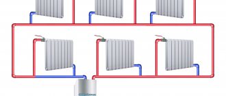
Boilers usually have rod-type sensors and are integrated with a heating element, which is convenient when performing repairs. In heating systems, the measuring part is installed on the return pipe and in any other place, and the thermostat is installed directly in front of the pump, which ensures the most efficient circulation of already mixed water.
Thanks to the flexible copper tube, the distance between the active part and the regulator can be up to 1 m.
Piezoelectric sensors
In this case, the underlying work scheme is only one. Such devices operate using a quartz piezoresonator. The operating principle and circuit diagram of the temperature sensor are as follows. The piezoelectric effect, which includes a change in the size of the piezoelectric element used, is subjected to a certain effect of electric current.
The essence of the work is quite simple. Thanks to the alternating supply of electric current with different phases, but the same frequency, the piezoelectric generator oscillates, the frequency of which depends on the specific measured temperature of the body or environment. As a result, the information received is interpreted into specific values in degrees Celsius or Fahrenheit. This type has one of the highest measurement accuracy. In addition, the piezoelectric version is used in situations where the durability of the device is required, for example, in water temperature sensors.
Thermoelectric or thermocouples
A fairly common method of measurement. The basic principle of operation is the generation of electric current in closed circuits of conductors or semiconductors. In this case, the places of adhesion must necessarily differ in temperature. One end is placed in the environment where the measurement needs to be taken, and the other is used to take readings. That is why this option is considered a remote temperature sensor.
Of course, it was not without certain drawbacks. The most significant of them can be called a very large measurement error. For this reason, this method is rarely used in many technological industries, where such a spread of values is simply unacceptable. An example is the TSP Metran-246 sensor for measuring the temperature of solids. It is actively used by metallurgical companies in production to control this parameter in bearings. The device is equipped with an analog output signal for reading, and the permissible measurement range is from -50 to +120 degrees Celsius.
Acoustic sensors
Extremely simple instruments that measure the speed of sound in various media. It is known that this parameter largely depends on temperature. In this case, other parameters of the measured medium should also be taken into account. One use case is measuring water temperature. The sensor produces data on the basis of which a calculation can be made, for which you will also need to know the initial information about the medium being measured.
The advantage of this method is the possibility of using it in closed containers. Typically used where there is no direct access to the medium being measured. The main consumer areas of this method, for quite natural reasons, are medicine and industry.
Semiconductor sensors
The operating principle of such devices is to change the pn characteristics and their transition under the influence of temperature. The measurement accuracy is very high. This is ensured by the constant dependence of the voltage on the transistor on the current temperature. In addition, the device is quite cheap and easy to manufacture.
For an example of such a temperature sensor, the LM75A device can serve as well as possible. The measurement range is from -55 to +150 degrees Celsius, and the error is no more than two degrees. It also has a fairly small step of about 0.125 degrees Celsius. The supply voltage varies from 2.5 to 5.5 V, while the signal conversion time does not exceed one tenth of a second.
Simple thermostats
Many radio amateurs know the so-called “trigger effect” at the threshold of operation of a thermal relay, photo relay, automatic charger, etc. The device can work normally dozens of times, but sometimes there is such an unpleasant moment when the executive relay turns on, immediately turns off, turns on again, etc. This phenomenon can manifest itself for quite a long time - the relay contacts “burn out”, and the operating time of the relay is not unlimited. If thyristors are used in the circuit, then if they are turned on and off frequently, they can heat up and fail, as well as interfere with the supply network. Figure 1 shows a diagram of a thermostat on a relay, in which there is no such harmful phenomenon as a “trigger effect”.
Let's assume that this thermostat is used to regulate the air temperature in the incubator. If the temperature in the incubator is below +38°C (set by variable resistor R4), the resistance of the thermistor R3 is relatively high and the comparator on DA1 is in positive saturation mode, transistors VT1 and VT2 are open, relay K1 is energized, and the air in the incubator is heated. When the temperature in the incubator reaches +38°C, the resistance of the thermistor R3 becomes less and the comparator is thrown into a state of negative saturation (common wire potential at the output), transistors VT1 and VT2 close, relay K1 releases. Due to the fact that resistor R2 is connected in series with resistor R1, which is shunted by the normally closed contacts of relay K1, the relay turns on at one temperature and turns off at another, i.e. The temperature in the incubator is maintained within, for example, +37.5...38°C. The required temperature difference is ensured by selecting resistor R2. Thus, such a harmful phenomenon as a “trigger effect” is absent in this thermostat circuit. The operating voltage of relay K1 must be at least 10 V, the relay contacts must withstand switched alternating current and be designed for a voltage of at least 250 V. The printed circuit board of the thermostat is shown in Fig. 2.
Figure 3 shows a circuit of a thermostat with a thyristor in the power section, which is also free from the “trigger effect” phenomenon.
Let's assume that this thermostat is also used for an incubator; the required air temperature in it should be within +38...39°C (this temperature range is set with variable resistor R4). A two-threshold comparator is made on the op-amp of the DA1 chip. If the temperature in the incubator is below +38°C, the resistance of the thermistor R3 is relatively high, and both comparators are in a state of positive saturation (log level “1” at their outputs). An RS flip-flop is built on logic elements DD1.2, DD1.3. If the air temperature in the incubator is below +38°C, there is a log “0” at the S input of the RS trigger (after the DD1.1 inverter), at the R input there is a log “1”, the trigger is in the “single” state (log ."0" at its inverse output 4 DD1.3). In this case, transistor VT1 is closed, a positive potential is applied to the control electrode of thyristor VS1 relative to its cathode, the thyristor is open, and the heating element Rн is turned on. When the air temperature in the incubator reaches +38°C, the resistance of the thermistor R3 decreases, the comparator on DA1.1 is transferred from a state of positive saturation to a state of negative saturation, its output is set to log "0", and at the input S of the trigger - log "1". , but the trigger remains in the “single” state, the RH heating element is on. When the air temperature in the incubator reaches +39°C, log “0” will appear at the output of the comparator DA1.2, which will set it to the “zero” state at the R input of the RS trigger. In this case, a log “1” will appear at pin 4 of DD1.3, which will open the transistor VT1, a low potential will be established on the control electrode of the thyristor VS1 relative to its cathode, the thyristor will close, and the heater will be disconnected from the supply network. When the air temperature in the incubator drops below +39°C, but above +38°C, the comparator DA1.2 will be set to a state of positive saturation, but the logic "1" at the input R of the trigger will not change its zero state, and the heater remains will be disabled. And only when the air temperature in the incubator drops below +38°C, the comparator DA 1.1 will be set to a state of positive saturation, and the log “0” will be sent to the input S of the trigger, which will turn on the heater Rн. Thus, the temperature in the incubator is maintained within the range of +38...+39°C (the required temperature difference is achieved by selecting the resistance of resistor R2), and the phenomenon of “trigger effect” is absent in this thermostat circuit. The thermostat printed circuit board is shown in Fig. 4.
When setting up and operating the device, you must be careful not to touch the parts, since the circuit contains network potential. For more accurate and smooth temperature control, it is advisable to select a variable resistor R4 (also in the circuit in Fig. 1). Diodes VD1-VD4 can be excluded. In this case, the heater Rн will only have one half-wave of the mains voltage, i.e. with a power of 500 W, 250 W will be released on the heater, and the reliability and durability of the heater itself will significantly increase. The voltage on the secondary winding of transformer T1 should be within 13...16 V.
Radioamator No. 12, 2005
List of radioelements
| Designation | Type | Denomination | Quantity | Note | Shop | My notepad |
| Thermostat circuit No. 1 | ||||||
| DA1 | Chip | K157UD2 | 1 | Search in the Otron store | To notepad | |
| VT1 | Bipolar transistor | KT3102V | 1 | Search in the Otron store | To notepad | |
| VT2, VT3 | Bipolar transistor | KT817G | 2 | Search in the Otron store | To notepad | |
| VD1-VD5 | Diode | KD209V | 5 | Search in the Otron store | To notepad | |
| VD6 | Zener diode | D814D | 1 | Search in the Otron store | To notepad | |
| C1 | Capacitor | 22 pF | 1 | Search in the Otron store | To notepad | |
| C2 | Electrolytic capacitor | 100 µF 50 V | 1 | Search in the Otron store | To notepad | |
| C3 | Electrolytic capacitor | 470 µF 16 V | 1 | Search in the Otron store | To notepad | |
| C4 | Capacitor | 0.1 µF | 1 | Search in the Otron store | To notepad | |
| R1, R5 | Resistor | 5.1 kOhm | 2 | Search in the Otron store | To notepad | |
| R2 | Resistor | 68 Ohm | 1 | Selected for temperature difference | Search in the Otron store | To notepad |
| R3 | Thermistor | 6.8 kOhm | 1 | Search in the Otron store | To notepad | |
| R4 | Variable resistor | 22 kOhm | 1 | Search in the Otron store | To notepad | |
| R6 | Resistor | 10 kOhm | 1 | Search in the Otron store | To notepad | |
| R7 | Resistor | 30 kOhm | 1 | Search in the Otron store | To notepad | |
| R8 | Resistor | 560 Ohm | 1 | Selected when setting up the power supply | Search in the Otron store | To notepad |
| T1 | Transformer | Output 12-15V 5W | 1 | Search in the Otron store | To notepad | |
| FU1 | Fuse | 0.5 A | 1 | Search in the Otron store | To notepad | |
| K1 | Relay | Not lower than 10 V | 1 | Search in the Otron store | To notepad | |
| Switch | 1 | Search in the Otron store | To notepad | |||
| Thermostat circuit No. 2 | ||||||
| DA1 | Chip | K157UD2 | 1 | Search in the Otron store | To notepad | |
| DD1 | Chip | K561LA7 | 1 | K176LA7 | Search in the Otron store | To notepad |
| VT1 | Bipolar transistor | KT605BM | 1 | Search in the Otron store | To notepad | |
| VT2 | Bipolar transistor | KT817G | 1 | Search in the Otron store | To notepad | |
| VS1 | Thyristor | Т122-25 | 1 | Search in the Otron store | To notepad | |
| VD1-VD4 | Diode | KD203D | 4 | Search in the Otron store | To notepad | |
| VD5-VD8 | Diode | KD209V | 4 | Search in the Otron store | To notepad | |
| VD9 | Zener diode | D814D | 1 | Search in the Otron store | To notepad | |
| C1, C2 | Capacitor | 22 pF | 2 | Search in the Otron store | To notepad | |
| C3 | Electrolytic capacitor | 100 µF 50 V | 1 | Search in the Otron store | To notepad | |
| C4 | Electrolytic capacitor | 470 µF 16 V | 1 | Search in the Otron store | To notepad | |
| C5 | Capacitor | 0.1 µF | 1 | Search in the Otron store | To notepad | |
| R1, R5 | Resistor | 5.1 kOhm | 2 | Search in the Otron store | To notepad | |
| R2 | Resistor | 68 Ohm | 1 | Selected for temperature difference | Search in the Otron store | To notepad |
| R3 | Thermistor | 6.8 kOhm | 1 | Search in the Otron store | To notepad | |
| R4 | Variable resistor | 10 kOhm | 1 | Search in the Otron store | To notepad | |
| R6, R7 | Resistor | 22 kOhm | 2 | Search in the Otron store | To notepad | |
| R8 | Resistor | 10 kOhm | 1 | Search in the Otron store | To notepad | |
| R9 | Resistor | 100 Ohm | 1 | 0.5 W | Search in the Otron store | To notepad |
| R10 | Resistor | 560 Ohm | 1 | 0.5 W Selected when setting up the power supply | Search in the Otron store | To notepad |
| SA1.1, SA1.2 | Double switch | 1 | Search in the Otron store | To notepad | ||
| T1 | Transformer | Output 12-15 V 5 W | 1 | Search in the Otron store | To notepad | |
| FU1 | Fuse | 0.5 A | 1 | Search in the Otron store | To notepad | |
| Add all | ||||||
Tags:
- Thermostat
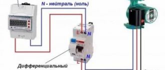
Connection options
- To the heated floor system;
- To the heating element;
- To the heater.
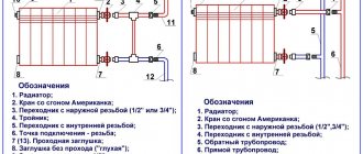
Connecting a thermostat to a heated floor system
A standard underfloor heating thermostat is supplied with detailed instructions for connecting the device to the underfloor heating system. You can connect the TP yourself using the markings under the terminal blocks.
Underfloor heating mat
On the back of the regulator there are three pairs of terminal sockets for wires. The first pair is intended for connecting a two-core network cable. Socket “L” – phase, “N” – zero.
The second pair of sockets is intended for connection to the underfloor heating terminals – L1 and N1. The fifth and sixth terminals are used to connect to the temperature sensor.
Connecting the thermostat
Floor temperature regulators can be inserted into a socket box or mounted on the wall. The temperature sensor can be either built into the body of the device or installed at the end of an external cable.
In the first case, the air temperature inside the room is measured. In the second option, the sensor measures the degree of heating of the final floor covering.
Connecting the thermostat to the heating element
The thermostat must be connected to the electric heater through a magnetic starter. This is due to the fact that the power of the regulator is far from comparable to the power of heating elements.
A magnetic starter (MP) is needed when the thermostat controls several heating devices at once. The MP is cut into the phase wire in parallel with the thermostat. Adjustment of the operating modes of the heaters is carried out by a thermostat, the supply current passes through the MP. This makes it possible to use a three-phase power supply, which allows the operation of high-power heating elements.
Many TRs are equipped with electronic microprocessors, which additionally provide indicators of the level of humidity, pressure and time required to achieve the values of the specified parameters.
Connecting the thermostat to the heater
Thermostats can be mechanical or electronic. Recently, the second models have been actively displacing their mechanical counterparts. The use of modern electronics makes it possible to more effectively control the temperature in a given environment.
TRs for room heaters are built into heater housings or placed away from heating devices. The regulator, first of all, is connected to the electrical network, then through the control circuit it is connected directly to the temperature sensor.
Additional Information. In most cases, infrared heaters are connected to a thermostat via a magnetic starter. To connect the device correctly, you must strictly follow the instructions provided.
Features of how temperature control devices are connected depend on the type of heating devices. This can be a single-core or two-core connection of TP underfloor heating. The connection of a two-phase thermostat to three-phase current heating elements is carried out only through a magnetic starter. For water heating, the thermostat is embedded directly into the radiator. Each specific case has its own thermostat connection diagram.