Calculation of water consumption over the cross-section of a water pipe serves as the starting point in a complex system of hydrodynamic calculations. When constructing or reconstructing a building, or when installing a fire extinguishing system, it is extremely necessary to calculate how much water will flow to the facility at a known pressure in the system if pipes of a certain cross-section are installed.
When calculating water flow, several factors are taken into account, some of the most important are the cross-section of the supply pipe and the pressure in the system
What factors are taken into account when calculating water consumption?
Determining water flow by pipe diameter allows you to obtain data that is very close to real, but not always. In addition to the pipe diameter, the real flow rate is affected by a number of factors:
- pressure level. With higher pressure in the pipeline system, consumers will receive a larger volume of water. Calculating water flow by pipe diameter and pressure allows you to obtain more accurate data than using only one parameter. Based on these values, the required pipe wall thickness is determined;
- The water pressure in the system depends on changes in the diameter of the pipes, bends and turns, branches, and the presence of shut-off valves. The more complex the configuration of the water supply system, the more difficult it is to determine the real indicators of water flow through the pipe at the pressure specified in accordance with SNiP;
- the force of friction that impedes the movement of water flow; with a greater length of the system, the flow of water through the pipe is significantly reduced, since the speed of movement of the liquid decreases;
- roughness of the internal walls of the water pipe. Modern polymer structures have approximately ten percent higher throughput than the newest products made from traditional materials - concrete, cast iron and steel;
- During long-term operation, the internal surface of the pipeline becomes clogged with various deposits. Changes in the internal topography due to contamination can hardly be calculated using mathematical formulas. So, it will be impossible to accurately determine the amount of water passing through the pipe. New polymer materials make it possible not to take into account the factor of gradual blockage of the system, since the formation of growths on their inner surface is practically eliminated.
Water consumption will depend on the configuration of the water supply system, as well as the type of pipes from which the network is installed
So, when calculating water pressure depending on the diameter of the pipe, without taking into account other factors that affect the actual flow of liquid, significant errors can be made.
How to Calculate Bandwidth
The tabular method is the simplest. Several calculation tables have been developed: you can choose the one that is suitable depending on the known parameters.
Calculation based on pipe section
SNiP 2.04.01-85 proposes to find out the amount of water consumption by the girth of the pipe.
| External section of the line (mm) | Approximate amount of liquid | |
| In liters per minute | In cubic meters per hour | |
| 20 | 15 | 0,9 |
| 25 | 30 | 1,8 |
| 32 | 50 | 3 |
| 40 | 80 | 4,8 |
| 50 | 120 | 7,2 |
| 63 | 190 | 11,4 |
In accordance with SNiP standards, daily water consumption by one person is no more than 60 liters. This data is for a home without running water. If a water supply network is installed, the volume increases to 200 liters.
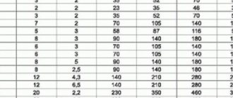
Calculation based on coolant temperature
As the temperature rises, the permeability of the pipe decreases - the water expands and thereby creates additional friction.
You can calculate the necessary data using a special table:
| Pipe section (mm) | Bandwidth | |||
| By heat (hl/h) | By coolant (t/h) | |||
| Water | Steam | Water | Steam | |
| 15 | 0,011 | 0,005 | 0,182 | 0,009 |
| 25 | 0,039 | 0,018 | 0,650 | 0,033 |
| 38 | 0,11 | 0,05 | 1,82 | 0,091 |
| 50 | 0,24 | 0,11 | 4,00 | 0,20 |
| 75 | 0,72 | 0,33 | 12,0 | 0,60 |
| 100 | 1,51 | 0,69 | 25,0 | 1,25 |
| 125 | 2,70 | 1,24 | 45,0 | 2,25 |
| 150 | 4,36 | 2,00 | 72,8 | 3,64 |
| 200 | 9,23 | 4,24 | 154 | 7,70 |
| 250 | 16,6 | 7,60 | 276 | 13,8 |
| 300 | 26,6 | 12,2 | 444 | 22,2 |
| 350 | 40,3 | 18,5 | 672 | 33,6 |
| 400 | 56,5 | 26,0 | 940 | 47,0 |
| 450 | 68,3 | 36,0 | 1310 | 65,5 |
| 500 | 103 | 47,4 | 1730 | 86,5 |
| 600 | 167 | 76,5 | 2780 | 139 |
| 700 | 250 | 115 | 4160 | 208 |
| 800 | 354 | 162 | 5900 | 295 |
| 900 | 633 | 291 | 10500 | 525 |
| 1000 | 1020 | 470 | 17100 | 855 |
For plumbing, this information is not extremely important, but for heating circuits it is considered the main indicator.
Find data based on pressure
When selecting pipes for installing any communication network, you need to take into account the flow pressure in the common line. If pressure under high pressure is provided, it is necessary to install pipes with a larger cross-section than when moving by gravity. If these parameters are not taken into account when selecting pipe sections, and a large water flow is passed through small networks, they will begin to make noise, vibrate and quickly become unusable.
To find the highest calculated water flow, use a table of pipe capacity depending on the diameter and various water pressure indicators:
| Consumption | Bandwidth | |||||||||
| Pipe section | 15 mm | 20 mm | 25 mm | 32 mm | 40 mm | 50 mm | 65 mm | 80 mm | 100 mm | |
| Pa/m | Mbar/m | Less than 0.15 m/s | 0.15 m/s | 0.3 m/s | ||||||
| 90,0 | 0,900 | 173 | 403 | 745 | 1627 | 2488 | 4716 | 9612 | 14940 | 30240 |
| 92,5 | 0,925 | 176 | 407 | 756 | 1652 | 2524 | 4788 | 9756 | 15156 | 30672 |
| 95,0 | 0,950 | 176 | 414 | 767 | 1678 | 2560 | 4860 | 9900 | 15372 | 31104 |
| 97,5 | 0,975 | 180 | 421 | 778 | 1699 | 2596 | 4932 | 10044 | 15552 | 31500 |
| 100,0 | 1000,0 | 184 | 425 | 788 | 1724 | 2632 | 5004 | 10152 | 15768 | 31932 |
| 120,0 | 1200,0 | 202 | 472 | 871 | 1897 | 2898 | 5508 | 11196 | 17352 | 35100 |
| 140,0 | 1400,0 | 220 | 511 | 943 | 2059 | 3143 | 5976 | 12132 | 18792 | 38160 |
| 160,0 | 1600,0 | 234 | 547 | 1015 | 2210 | 3373 | 6408 | 12996 | 20160 | 40680 |
| 180,0 | 1800,0 | 252 | 583 | 1080 | 2354 | 3589 | 6804 | 13824 | 21420 | 43200 |
| 200,0 | 2000,0 | 266 | 619 | 1151 | 2488 | 3780 | 7200 | 14580 | 22644 | 45720 |
| 220,0 | 2200,0 | 281 | 652 | 1202 | 2617 | 3996 | 7560 | 15336 | 23760 | 47880 |
| 240,0 | 2400,0 | 288 | 680 | 1256 | 2740 | 4176 | 7920 | 16056 | 24876 | 50400 |
| 260,0 | 2600,0 | 306 | 713 | 1310 | 2855 | 4356 | 8244 | 16740 | 25920 | 52200 |
| 280,0 | 2800,0 | 317 | 742 | 1364 | 2970 | 4356 | 8568 | 17338 | 26928 | 54360 |
| 300,0 | 3000, | 331 | 767 | 1415 | 3078 | 4680 | 8892 | 18000 | 27900 | 56160 |
The average pressure in most risers varies from 1.5 to 2.5 atmospheres. The dependence on the number of floors is regulated by dividing the water supply network into several branches. Injecting water through pumps also affects the change in flow speed.
Also, when calculating the water flow through a pipe using a table of pipe diameter and pressure values, not only the number of taps is taken into account, but also the number of water heaters, bathtubs and other consumers.
Hydraulic calculation according to Shevelev
To most accurately identify the indicators of the entire water supply network, special reference materials are used.
They define the running characteristics for pipes made of different materials. An example of a good example for calculations is Shevelev’s table. This is a voluminous reference book. You don't have to go to the library to use it. All the necessary data can be found on the World Wide Web. In addition, there are electronic programs based on Shevelev tables. It is enough to enter the required parameters to get the finished result.
Application of formulas
The use of different formulas depends on the known data. The simplest of them is: q = π×d²/4 ×V. In the formula: q shows the water flow in liters, d is the cross-section of the pipe in cm, V is the speed indicator of the advance of the hydraulic flow in m/sec.
Speed parameters can be taken from the table:
| Type of water supply | Speed (m/sec) |
| City water supply | 0,60–1,50 |
| Main pipeline | 1,50–3,00 |
| Central heating network | 2,00–3,00 |
| Pressure system | 0,75–1,50 |
When connecting additional injection devices, it is necessary to take into account the coefficient of pressure created. It is listed in the user manual.
Knowing what characteristics pipes have is necessary to correctly connect plumbing fixtures. With the correct selection of data, there will be no reason to worry that when you open the tap in the bathroom, the water in the kitchen will stop flowing or its pressure will decrease.
Source
Methods for calculating the amount of water over a pipe cross-section
Pipeline capacity can be calculated using several different techniques. You can use:
- physical calculation methods using special formulas that are different when carrying out calculations for water supply and sewerage systems;
- tabular calculation methods that provide approximate values, which in most cases is sufficient for making subsequent decisions. To obtain accurate values, use the Shevelev tables. In addition to the internal cross-section, these tables take into account a number of other parameters, the influence of which affects the throughput of the pipeline;
- special free online calculators;
- special computer programs for calculating various parameters related to the operation of the pipeline system. Large Russian companies use the paid domestic program “Hydrosystem”. You can find links on the Internet that allow you to use the TAScope program, which is widely used in many countries.
Calculation of water consumption by diameter and other parameters
Obtaining calculated water consumption data allows you to determine:
- with the selection of pipes of the required diameter, which is linked to the expected throughput;
- with the thickness of their walls, associated with the expected internal pressure;
- with materials that will be used when laying the pipeline;
- with backbone installation technology.
Calculating water consumption allows you to choose the right type of pipes and their diameter
It is possible to calculate the volume of water consumed using a simple formula:
q= π×d2/4 ×V
The given formula uses the following parameters: d – internal diameter of the pipe; V – water flow velocity; q is the amount of water flow.
Note! For the calculation, the features of the speed of the water flow are not important, which can be either natural, with gravity movement, or created artificially using a forcing external source.
In a free-flow system, where water moves by gravity from a water tower, the speed of the water flow ranges from 0.7 m/s to 1.9 m/s (in a city water supply system, the water flow usually moves at a speed of one and a half meters per second). When using an external source for injection, the speed it imparts is determined from the data sheet of the supercharger.
The given formula includes three parameters and allows, knowing two of them, to determine the third.
Calculation of pipe diameter based on water flow
Determining the correct water flow
To determine the diameter of the pipe based on the flow rate of the passing liquid, you will need the values of the true water consumption, taking into account all plumbing fixtures: bathtub, kitchen faucet, washing machine, toilet. Each individual section of the water pipeline is calculated using the formula:
qc = 5× q0 × α, l/s
where qc is the value of water consumed by each device;
q0 is a standardized value, which is determined according to SNiP. We take for a bath - 0.25, for a kitchen faucet 0.12, for a toilet -0.1;
a is a coefficient that takes into account the possibility of simultaneous operation of plumbing fixtures in the room. Depends on the probability value and the number of consumers.
a = f (N × P)
In sections of the main line where water flows for the kitchen and bath, for the toilet and bath, etc. are combined, a probability value is added to the formula. That is, the possibility of simultaneous operation of a kitchen faucet, bathroom faucet, toilet and other appliances.
The probability is determined by the formula:
Р = qhr µ × u/q0 × 3600 × N,
where N is the number of water consumers (appliances);
qhr µ is the maximum hourly water flow that can be accepted according to SNiP. For cold water we select qhr µ =5.6 l/s, total flow rate 15.6 l/s;
u – number of people using plumbing fixtures.
Example of calculating water consumption:
The two-story house has 1 bathroom, 1 kitchen with installed washing machine and dishwasher, shower, 1 toilet. A family of 5 lives in the house. Calculation algorithm:
- We calculate the probability P = 5.6 × 5/0.25 × 3600 × 6 = 0.00518.
- Then the water consumption for the bathroom will be qc = 5 × 0.25 × 0.00518 = 0.006475 l/s.
- For the kitchen qc = 5 × 0.12 × 0.00518 = 0.0031 l/s.
- For a toilet, qc = 5 × 0.1 × 0.00518 = 0.00259 l/s.
Calculate the pipe diameter
There is a direct relationship between the diameter and the volume of flowing liquid, which is expressed by the formula:
Q = (πd²/4)•w
where Q is water flow, m3/s;
d – pipeline diameter, m;
w – flow velocity, m/s.
By transforming the formula, you can select the value of the pipeline diameter, which will correspond to the consumed volume of water:
Yulia Petrichenko, expert
d = √(4Q/πw), m
The water flow rate can be taken from Table 2. There is a more complex method for calculating the flow rate - taking into account losses and the coefficient of hydraulic friction.
This is a rather voluminous calculation, but in the end it allows you to get an accurate value, unlike the tabular method. Table 2. Liquid flow rate in the pipeline depending on its characteristics
| Pumped medium | Optimal speed in the pipeline, m/s | |
| LIQUIDS | Gravity movement: | |
| Viscous liquids | 0,1-0,5 | |
| Low viscosity liquids | 0,5-1 | |
| Pumpable: | ||
| Suction line | 0,8-2 | |
| Discharge pipeline | 1,5-3 | |
| GASES | Natural craving | 2-4 |
| Low pressure (fans) | 4-15 | |
| High pressure (compressor) | 15-25 | |
| COUPLES | Overheated | 30-50 |
| Saturated vapor at pressure | ||
| More than 105 Pa | 15-25 | |
| (1-0.5)*105 Pa | 20-40 | |
| (0.5-0.2)*105 Pa | 40-60 | |
| (0.2-0.05)*105 Pa | 60-75 | |
Example: Let's calculate the diameter of the pipe for the bathroom, kitchen and toilet based on the obtained water consumption values. We select from Table 2 the value of the water flow speed in the pressure water supply pipe – 3 m/s.
Then the diameter of the pipeline is determined:
for the bathroom d = √(4*0.006475/3.14*3)=0.052 m
for toilet d = √(4*0.00259/3.14*3)=0.033 m
for the kitchen d = √(4*0.0031/3.14*3)=0.036 m
Determination of water flow with a possible drop in pressure
The considered formula for determining water flow by the internal diameter of the pipe and the speed of water flow is considered simplified. It does not take into account changes in pressure due to circumstances that could lead to lower or higher pressure in the pipeline system. The Darcy formula allows you to make a calculation that takes into account losses at the extreme points of the pipeline. She looks like this:
ΔΡ = λL/D*V2/2gρ
The Darcy formula takes into account the following parameters:
P – viscosity; λ – friction coefficient, the value of which is determined:
- the configuration of the pipeline, straight or having complex turns and bends;
- turbulence of water flow;
- roughness of the inner surface of the pipes;
- the presence of obstacles in the form of areas with the use of shut-off valves.
The friction coefficient is affected by the presence of locking elements and their number
L – pipe length; D is the size of the internal section; V – speed of movement of the water flow; g – free fall acceleration.