Buying expensive equipment for organizing heating in a rarely visited country house, bathhouse or small house is not always advisable. It is especially unreasonable if the country property is not constantly supervised and a security alarm is not installed. What to do if heating is still required from time to time?
A homemade gas boiler, assembled from scrap materials or used household units, can handle heating quite successfully. A device made with your own hands can become the pride of the owner. Building a gas-powered structure will show off your craftsmanship.
The article we have proposed describes in detail the steps for assembling and modernizing gas units that can adequately heat private buildings. We have given as examples the most popular, practice-tested homemade options. Our advice will ensure home craftsmen success in a difficult task.
The manufacturing process of an atmospheric gas burner
An atmospheric burner is easier to build, since it is structurally much simpler than its fan counterpart. The most typical example known to most Russians is the burner block in old-style geysers. There are no energy-dependent elements in its design that force gas and air to mix in the required proportions.
Air is drawn into the chamber with the atmospheric burner module spontaneously as needed. Blue fuel processing products are discharged naturally through a standard chimney due to the presence of draft. All the work consists of constructing a manifold with gas nozzles through which gas will flow at the required speed.
If you want to build a gas burner with your own hands, it is better to take a factory-made product as a basis, or rather, the drawing available in its technical passport with the dimensions and designation of structural elements
To make a burner with your own hands to equip a gas heating boiler, you will need:
- Valve series VK-74. Typically used on oxygen cylinders, designed for a maximum pressure of 20 mPa. The package should include a 3/4″ union nut, with which you can tightly connect to the gas supply pipe or hose. The valve will serve as a support base for fixing the nozzle.
- Nozzle cap. The device will hold the gas supply dispenser and form a narrowly directed jet. A hole is drilled at the top of the cap into which the nozzle is to be placed. The base screws onto the valve.
- Nozzle. It is better to buy it ready-made with the expectation of supplying main gas or a liquefied gas mixture. The injectors have different outlet diameters. Instead of nozzles for boilers, you can use a jet from a gas burner.
- Homemade injector. It is constructed from a steel tube with a wall thickness of up to 2 mm. You will need a piece of pipe approximately 10 cm long.
- Piezo element. It is installed at will, although you can do without it. Homemade products can be set on fire with matches.
All of the above elements are assembled mainly by welding. Therefore, skills and minimal knowledge in welding will be very useful for an enterprising “do-it-yourselfer”. However, where it is possible to use threads, it should remain a priority.
The gas supply channel must be impeccable and sealed, because safety depends on its condition. A distance of 10 cm must be maintained between the gas inlet into the device and the nozzle, which is necessary for mixing fuel with air.
Image gallery
Photo from
Large gas burner
Gas burner combustion process
Ignition of the atmospheric burner block
Burning oxygen indoors
The home craftsman just has to figure out how to secure a homemade gas burner in the combustion chamber of a used water heater or in the firebox of a former wood-burning boiler. Please note that you need to leave room for air flow. Air must be regularly supplied to the chamber, for which round or longitudinal holes must be cut in the door.
Do not forget that the above option can hardly be called a safe gas supply device. The design does not have automatic equipment that interrupts the operation of the boiler in case of blowing out or unstable flame. Owners will not have the opportunity to adjust the pressure and gas flow, so there can be no talk of either convenience or savings.
Design features
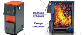
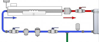
As for the design of an air-conditioned heating boiler, it is not much different from a conventional gas one. Nevertheless, some differences are still present, and their role is obvious. The key elements of the system include:
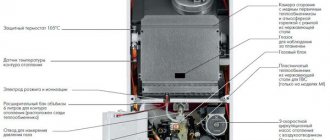
- A fuel combustion chamber with a burner, ventilation equipment and a fuel mixture supply element.
- Primary heat exchanger.
- A chamber for cooling the mixture to a temperature equal to the “dew point” (+56...+57°C).
- A secondary heat exchanger in which condensation processes take place.
- Condensate storage container.
- A chimney through which cold flue gases are removed.
- Pump for circulating fluid in the system.
The task of the primary heat exchanger connected to the combustion chamber is to cool the evolved gases to a temperature that is much higher than the “dew point” (traditional convection-type gas boilers operate on a similar principle). After this, the smoke mixture moves to a secondary heat exchanger, in which additional cooling is carried out to temperatures below +56°C. In this case, the water vapor turns into condensate and accumulates on the walls of the heat exchanger, and then collects in a special container and flows into the sewer hole.
The liquid, which is used as a coolant, moves opposite to the direction of the vapor mixture. In turn, the cold water passes through the condensing heat exchanger and is heated, and then passes into the primary heat exchanger and becomes even hotter.
Installing a gas burner in a solid fuel boiler
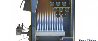
After sound reflection and a real assessment of their capabilities, most home craftsmen still give preference to the modernization of solid fuel boilers that previously processed firewood or coal. A factory-made gas burner is simply placed in their firebox.
To equip your country property, you can purchase a solid fuel unit, which can be converted into a gas one. For example, a Teplodar stove in which a gas burner is mounted
Let's consider the stages of installing a Teplodar AGG burner device:
- Dismantling the firebox door, the ashpan damper (or the ashpan itself, if it is made in the form of a drawer with a solid door), the bumper and the grate. In short, you need to remove all structural parts located within the firebox and ash pan.
- Fixing the burner device. A burner block is mounted in the firebox channel freed from the above elements. If the Teplodar stove is designed for changing fuel, then the burner module is fixed in the channel through standard ears with screws and nuts threaded into them.
- Connecting automation to the remote control. The devices included in the design of the burner block that ensure automatic operation of the boiler are connected to the control panel.
- Thermostat sensor mount. It is installed on the supply pipe, wrapped in insulation to protect against external mechanical and temperature influences, and on top with ties.
- Putting it into operation. It is carried out after checking the draft and burst ventilation of the room with a modernized boiler. Using a simple handle, you select the most suitable mode.
We remind you that in accordance with the requirements outlined in the “Safety Rules for Gas Distribution and Gas Consumption Systems”, all work on installing equipment, replacing burners, servicing equipment and connecting to the network supplying blue fuel must be carried out by gas workers.
The technical documentation attached to the Teplodar stove contains a detailed description of the process of installing a gas burner for converting a solid fuel unit into a gas one
In accordance with federal regulations and standards, it is necessary to conclude an agreement with representatives of gas services for the supply of gas and related services. It is clear that not all remote settlements will be able to be served by employees of gas organizations. However, it is advisable to adhere to the requirements in order to avoid catastrophic consequences.
When it decreases and suddenly goes out, the current coming from the electrical element is weakened, as a result of which the gas supply channel is blocked. Overheating of water in the boiler is detected by a temperature sensor, which transmits a signal to open the contact pair blocking the burner
Should you take risks or value and protect your health with the well-being of your loved ones? It's up to you to decide. It is wiser to refuse threatening measures, but knowing about the process of their implementation is very useful in order to monitor how efficiently and honestly the gas workers work.
Design of systems with condensing boilers
Oddly enough, there are still many people who do not fully understand the functioning mechanism of a condensing boiler, which is why serious mistakes occur when designing a heating system. As a result, expensive equipment does not produce full power and turns into a completely ordinary gas boiler, only more cumbersome. Let us briefly recall [1] what the condensation mechanism is, which adds extra percentages of power to the boiler. Condensation is an exothermic process in which the heat of phase transition is released, otherwise called the heat of condensation. The temperature at which condensation begins to form is called the dew point. The mixture of water vapor and other gaseous compounds that make up the flue gases condense at various temperatures, for example, a temperature of about 55-57 °C (natural gas), 47 °C (fuel oil), etc. (Table 1). In Fig. Figure 1 presents a comprehensive graph reflecting various operating parameters of the heating system. The scale on the left shows the temperature of the supply and return boiler circuits, on the bottom scale - the outside air temperature, on the scale on the right - the load of the heating system: at 100% the boiler operates at full power. The location of the temperature graph of the boiler circuit below the line indicating the dew point means that condensation occurs at this moment. Above the line, condensation does not occur. This most important distinctive feature of a condensing boiler implies that the designer cannot use standard templates and usual calculations when calculating the system. After all, the methods given in textbooks are aimed, as a rule, precisely at reducing condensation formation, which is detrimental to a traditional boiler. In addition, there are certain restrictions related to smoke removal: the design and material of the chimney, condensate drainage, etc., as well as heating sanitary water for domestic needs. A distinction is made between complete and partial condensation. Complete condensation occurs when the entire volume of flue gases is cooled to the dew point temperature. Partial condensation is much more common. In this case, the main flow of gases does not reach the dew point and flies away, so to speak, untreated. Only a small portion passing directly next to the walls of the heat exchanger is cooled sufficiently to condense. Data showing how efficient a condensing boiler can be compared to a conventional one is presented in table. 1. Theoretically, when burning 1 m3 of natural gas, 1.63 liters of water can condense. Based on this value, the efficiency of the system is determined. For example, if, according to the gas meter readings, 30 m3 of gas was consumed, the maximum possible condensate yield is 30? 1.63 = 48.9 l. In reality, only 30 liters of condensate were released. This means that the efficiency of the system in this case is 30/48.9 = 0.613, or 61.3%. Note that measurements must be carried out over a long period of time and repeatedly, because the amount of condensate depends on many parameters - outside temperature, rate of hot water consumption, etc. When taking measurements, it does not hurt to correctly estimate the possible volumes, so as not to make a mistake with the container for collecting moisture. Thus, when heating an individual country house for one family, up to 15 liters of condensate can be released during the day. Let's take a closer look at the design features of heating systems based on condensing boilers. Reducing the coolant temperature
The flue gases are cooled to the temperature of the coolant entering the boiler, so it is necessary that it be below the dew point.
To enhance the effect, it is desirable that the supply line is also heated to a temperature of no more than 55–57 °C. The ideal option here would be to install heated floors throughout the house with a temperature range of 40/30 °C. But for various reasons this option is not always possible. In most cases, the cold Russian climate requires the installation of radiators. Usually they are calculated based on values of 80/60 °C or even 90/70 °C, some manufacturers even give an option of 100/80 °C. In our case, it is proposed to take the lowest value of the temperature pair from the manufacturer’s catalog. It is indicated either explicitly or is determined based on available data for other temperatures using conversion factors according to the formula [2]: Here, the formula Q is the thermal power of the radiator under operating conditions, W; Qnom - normalized thermal power of the radiator, W; n is the exponent of the radiator characteristic for heating a room, taken from the technical characteristics tables for the corresponding type of heating device (determined during independent testing and registration of heating devices); ?tln - temperature rise [°C], calculated as: where tv - flow temperature, °C; tr—return line temperature, °C; tl is the temperature in the heated room, °C. A simplified calculation can be made using the tables provided by the manufacturer, compiled on the basis of the German standard DIN EN 442. On average, when the temperature regime changes from 90/70 to 75/65 at a room temperature of 20 °C, the radiator power decreases by 20%, from 90/70 to 70/55 - by 35%. As a result, radiators with a much larger heat exchange area and, as a result, greater capacity will be required. This increases the total volume of coolant in the system and requires careful selection of the circulation pump based on calculations. An empirical approach based on simplified maxims (for a boiler of such and such power, such and such a pump is enough) will no longer work. Also, apparently, an expansion tank of increased capacity will be required. When installing a low-temperature controlled circuit with a three-way mixer, it is advisable to calculate the performance of the circulation pump of this circuit so that the volume of water flowing through it exceeds the flow through the boiler circuit pump. Otherwise, the return temperature will rise, which will prevent condensation. Reducing the return line temperature can also be achieved by using the return coolant of the radiator circuit as a supply coolant for heated floors (for more information about this method, see [4]). It is also necessary to abandon various devices that increase the return temperature of the boiler circuit, such as four-way valves, bypasses, preheating, etc. Unless they perform a protective function (the already mentioned bypass regulator). Great assistance in maintaining a consistently low water temperature in the boiler is provided by weather- and room-dependent regulation and daily programming. Reducing the coolant circulation rate in the system helps, but to a certain extent. Any boiler, and a condensing boiler is no exception, has a parameter called “minimum flow through the boiler”, if this is not met, the water in the tubes boils and the heat exchanger is destroyed. To prevent boiling in the boiler, of course, appropriate protection is installed that turns off the gas supply in emergency situations, but, firstly, it may not work, and secondly, such operation of the device “to the limit” reduces its service life and does not guarantee the calculated warming up the premises. You can protect the boiler from boiling using a bypass regulator, which in a critical situation will dump part of the heated water into the supply line. However, it must be remembered that this reduces the level of condensation or stops it altogether. In other words, it is much more profitable for the system and for the efficiency of the boiler to correctly select the coolant flow rate than to correct miscalculations later. The heat exchanger volume of a modern condensing boiler is 2–5 l; depending on the type of device, the minimum flow can be 400–600 l/h, at partial load – up to 200 l/h. This leads to quite frequent clocking (50 thousand times/year) of the pump and burner compared to boilers with a large volume (10 thousand times/year). The conclusion from this is: the more carefully the system is designed, the more nuances that can be taken into account at the planning stage, the better it will be possible to save expensive equipment. Heating water in the DHW circuit
If the temperature of the heating circuit can still be varied over a wide range (after all, we need to get only 20 °C in the room, to which, purely theoretically, the return line temperature can drop), such options are unacceptable when heating sanitary water.
The best option seems to be flow-through heating of hot water in a secondary heat exchanger using only a hot water tap during water tapping. Then the water will heat up to a temperature no higher than 45–50 °C, and condensation will take place. For a family of three or more people, however, flow-through heating may not be enough. In this case, it is advisable to install a cylinder water heater equipped with a heat exchanger. From the point of view of enhancing the condensation effect, it is advisable to choose a larger tank and heat the water in it to lower temperatures, if possible not higher than 60 ° C. But that is not all. In a conventional indirectly heated DHW water heater, the heat exchanger is located inside the water heating tank, often along almost the entire height of the tank. This leads to the need to always use a coolant with the highest possible temperature for heating. Lower temperatures can cause the already heated portion of the water to cool. As the water in the tank heats up, the return temperature rises more and more, less heat is transferred to the water, and condensation decreases. Therefore, for condensing boilers, we can recommend installing boilers with an external heat exchanger, called “layer-heated water heaters.” The operating principle of both types of boilers is shown in Fig. 2.The advantages of layer-by-layer heating include: almost instant readiness for use, since heating of the entire volume is not required; lower coolant temperatures (at least return), sufficient for condensation, because cold water always flows into the heat exchanger for heating. Removal of combustion products from a condensing boiler
The main problem in the removal of combustion products is their low temperature, low draft, and tendency to settle condensate, which is highly acidic. Therefore, a standard brick or steel chimney located on the roof of a building will not work here. The smoke simply does not have enough lift to overcome the height. In addition, the walls will quickly become unusable under the influence of acid. To do this, an insert made of acid-resistant material is made into the existing chimney. This can be aluminum, borosilicate glass, ceramics, fire-resistant chamotte clay, stainless steel, and various polymers. Typically, condensing boiler manufacturers also offer suitable flue pipes. When choosing a location for the thermoblock, you should also pay close attention to the maximum length of the air ducts; it is calculated based on the fan power of a particular device. Exceeding the maximum permissible parameters will lead to poor draft, insufficient access of combustion air and suboptimal system operation. It is also necessary to remember the acidity of the condensate. The condensate consists mainly of carbon oxides and various acids (carbonic, nitric, sulfuric) dissolved in water. When burning natural gas, its pH is 3.5–5.5 (about the same as beer or wine), while liquid fuel is 1.5–3.5 (like lemon juice or vinegar) due to its high sulfur content. You can get a visual idea of the acidity of some food products and flue gas condensate from the following diagram (Fig. 3). The acidity of the condensate should be taken into account when disposing of it. When operating gas boilers with a power of up to 200 kW, condensate can usually be drained into the central sewer. If you use an individual septic tank, you should definitely check whether the acids will harm the vital activity of bacteria. Boilers with a power of 200 kW, as well as liquid fuel modifications, produce condensate that is too caustic, which in its original form is not suitable for draining; it should be treated with a neutralizer (also purchased from the boiler manufacturer). Also important is the material of the sewer pipe through which the condensate will then flow . Acid-resistant materials are the following: porcelain stoneware, polyvinyl chloride (PVC), polyethylene for general purpose (PEHD), polypropylene (PP), acrylonitrile styrene acrylate (ASA), acrolonitrile butadiene styrene (ABS), internally enameled cast iron, internally polymer-coated steel, stainless steel, and borosilicate glass. By following the recommendations described in this article at the design stage, you can get excellent results after the start of operation. Preliminary calculations on paper will make it possible to calculate several possible options; after installing the system, making a correction will be much more difficult. 1. Wall-mounted condensing boilers. Market review // S.O.K. Magazine, No. 7/2010. 2. . Convector catalog 1/2010. 3. Buderus. "Radiators and components 2010". 4. Increasing the efficiency of a condensing boiler using pump groups // S.O.K. Magazine, No. 9/2009. 5. Vaillant. "Systems with floor-standing boilers." 6. Website www.brennwert.info.
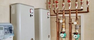
Boiler grounding
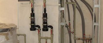
The boiler must be grounded. To do this, you will need a ready-made grounding loop from the store. It is located near the garage underground at a depth of about a meter. A steel strip is led from the grounding loop to the boiler. It is covered with a plastic box. For reliability, it is better to solder the joints of the steel strip with the boiler and the circuit.
Grounding a gas boiler is the key to its reliable and safe operation. It is necessary to do it
We make a UPS and connect the voltage stabilizer of the gas boiler
UPS is an uninterruptible power supply. It is needed to ensure that the equipment continues to work when the power is turned off. And the stabilizer will protect the boiler from overloads during frequent power surges in the network.
An uninterruptible power supply can be purchased at the store. But if you do it yourself, it will be cheaper
Stores sell a variety of uninterruptible power supplies and stabilizers. They are not cheap. You can try to make an uninterrupted unit yourself. It is impossible to make a stabilizer yourself. The rules for choosing it are:
- For a 220-volt network, choose a single-phase stabilizer; for a 380-volt network, choose a two-phase one.
- Power - from 20 to 40 kW depending on the volume of the boiler.
- The stabilizer can be installed on the floor or mounted on a wall - this does not affect its operation.
Focus on the following technical characteristics of the stabilizer:
- type - electronic or relay;
- response time - a few milliseconds;
- input voltage range - from 140 to 260 volts;
- operating temperature range - from +5 to +40 0C.
The stabilizer is mounted next to the boiler in a dry place where access to water is excluded. It should not be overheated or frozen.
A stabilizer for a gas boiler will help maintain the voltage in the network at the level required for the heater to operate
Video: why do you need a voltage stabilizer for a gas boiler
How to assemble an uninterruptible power supply with your own hands
To produce a UPS you need:
- current converter (220 volts). It is needed so that a voltage of 220 volts is supplied to the boiler from the battery;
- battery (helium batteries have proven themselves well);
- charger (minimum 15 amps).
The instructions for assembling the UPS look like this:
- The converter is connected to the battery using wires with a cross-section of 4 millimeters, observing polarity.
Usually there are “+” and “-” indicators at the connection points (sometimes the polarity is indicated by different colors of the wires). The positive from the converter must go to the positive from the battery. The same goes for the negative wire. The converter is connected to the battery using two wires. Their cross-section must be at least 4 millimeters - The boiler is connected to the converter via a socket. It is already included in the kit; there is no need to install anything additional. Thus, three parts of one system - the boiler, the converter and the battery - are connected to each other.
- When the battery is discharged, a charger is connected to it.
The converter is connected to the battery using wires, connecting plus to plus, and minus to minus.
Such a unit will not operate automatically. You will have to turn it on yourself when the electricity suddenly goes out.
Video: making a UPS with your own hands
Tips for choosing a gas heater
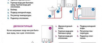
Despite the differences between main methane and liquefied hydrocarbons, the same equipment is used to effectively burn these substances. To switch from one fuel to another, the boiler installation is adjusted, described in the following sections of the publication.
Key moment. Any propane gas boiler successfully consumes natural gas and vice versa. It will not be possible to use both energy carriers at the same time or switch with one press of a button - the transition involves partial disassembly, replacement of the burner fuel nozzles and adjustment of the gas valve.
All heat generators that consume natural gas can operate on propane-butane.
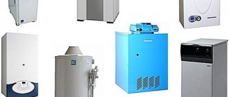
Accordingly, you need to choose and buy a heat generator for heating a private home according to the standard algorithm:
- Determine the power of the boiler unit. The best way is to calculate the thermal load for heating and multiply the result by a safety factor of 1.2. When buying a double-circuit boiler for hot water supply, set aside one and a half reserves.
- Choose a floor or wall model of the heat source. For a closed-type pumping system, it is better to take a suspended unit; for gravity distribution, a non-volatile stationary boiler.
- The optimal solution in the absence of a chimney duct is to install a turbocharged version of the heater with a closed combustion chamber. The removal of combustion products is organized through a double-walled coaxial chimney laid horizontally through the nearest outer wall.
- If you have an outlet channel and a limited budget, feel free to take an atmospheric heater, it will cost less than a supercharged model.
- Among dual-circuit installations, it is better to choose an option with a separate plate heat exchanger operating on DHW. It is easier to maintain such a water heating device than to clean a heat generator with a combined counterflow heater.
Note. For country houses and small apartments (up to 100 m²), there is a budget option - the so-called parapet boiler with a power of up to 12 kW. The unit is placed near an external wall and does not require the installation of a chimney - a short coaxial pipe leads directly to the street. Moreover, the combustion chamber is open, there is no fan and no electronics.
A set of nozzles designed to supply LPG
Initially, any of the listed heaters is designed to work with natural gas - methane. Since the caloric content of LPG is higher, the fuel jets in the boiler need to be replaced (popularly called injectors). Hence the advice: when purchasing a unit, immediately request an additional set of jets with smaller diameter holes intended for liquefied gas.
Since we are considering the problem of switching to LPG and the further operation of such installations, the topic of choosing a heat generator is covered concisely. You will find more useful information on this issue in another publication - how to choose an economical boiler for an apartment or private house.
Gas-generating heating boiler
The main difference between a gas generator boiler and other similar equipment is the volume of the loading chamber, which minimizes the need for regular maintenance of the heating unit. The presence of a programmable unit in the design facilitates the process of controlling the heating temperature. Gas generator-type boilers can operate on different types of fuel.
Of particular interest are universal models that operate on several types of energy resources and have a combustion chamber in a lower location.
Pyrolysis boiler
The installation of such a gas generator unit is simple, which is explained by the absence of the need to obtain an installation permit and the possibility of using almost any smoke exhaust systems.
Long-burning devices or gas-generating heating boilers have many advantages, including a low rate of fuel combustion, ease of operation and maintenance, absolute environmental safety, and an efficiency rate reaching 100%.
Choosing a gas generator boiler involves taking into account the significant weight of such equipment, as well as the energy dependence that is typical for some of the most complex models.