Additional equipment used in conjunction with hot water boilers is a blower fan (blowing fan) and a smoke exhaust fan. Blower fans are designed to pump air into the furnaces of boilers operating on liquid or solid fuels; smoke exhausters for boilers are used to remove flue gases from their furnaces. But the actual scope of their application is not limited to heating equipment alone. Depending on the specific conditions, a blower fan and a smoke exhauster can be used to move gas-air mixtures in any technological processes, the conditions of which correspond to their technical characteristics.
Device
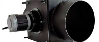
The blower fan and smoke exhauster are designed in the same way and consist of the following main components:
- Frame. It is made in the shape of a snail, has two flanged pipes - suction (in the center, on the same axis with the impeller) and discharge (at the periphery).
- The impeller is centrifugal type.
- Drive unit. It consists of an electric motor on the shaft of which an impeller is mounted, or includes an intermediate shaft with a bearing unit that transmits rotation from the engine to the impeller through a coupling connection or a belt drive. The presence of an intermediate shaft allows you to change bearings without removing the impeller.
- Frame. Used to secure the machine to the base. May be common or separate for the motor and fan housing.
The spiral housing of the fan (smoke exhauster) can be rotated from 0 to 270° with a fixed value every 15°. The reference point for the angle is the horizontal plane.
Depending on the direction of rotation of the impeller, fans can be of right rotation (for a blower fan: clockwise movement, when viewed from the suction pipe, for a smoke exhauster: clockwise movement, when viewed from the engine side) or left rotation (for a blower fan : counterclockwise movement when viewed from the suction side, for a smoke exhauster: counterclockwise movement when viewed from the engine side). The direction of rotation is indicated by an arrow on the fan housing. When choosing a fan, it is important to correctly determine the direction of rotation and the angle of the housing.
When operating as boiler equipment, fans must be equipped with control dampers. The damper on the blower fan regulates the amount of air supplied to the boiler, and the damper damper regulates the amount of draft in the firebox and flues.
Some fan models (VDN, in particular) can optionally be equipped with a guide device attached to the suction pipe. It is a round box with rotating blades that direct the incoming flow along the direction of rotation of the impeller, thereby reducing aerodynamic drag.
Smoke exhausters, draft machines and mill fans for boiler units
Single-suction centrifugal smoke exhausters of type D are designed for suction of flue gases from the furnaces of boiler units equipped with effective ash collection systems, as well as for suction of flue gases from the furnaces of gas-oil boiler units.
Smoke exhausters are designed for long-term operation indoors and outdoors in temperate climates (climatic version U, placement categories 1, 2, 3 and 4, GOST 15150-69). Starting of smoke exhausters is permitted at a temperature in the snail not lower than -30oC. The maximum gas temperature at the inlet to smoke exhausters should not exceed +200oC. For the durability of D type smoke exhausters, the wall thickness of the volutes is increased compared to VD type fans.
Centrifugal single-suction smoke exhausters type DN are designed for suction of flue gases from the furnaces of boiler units equipped with effective ash collection systems, as well as for suction of flue gases from the furnaces of gas-oil boiler units.
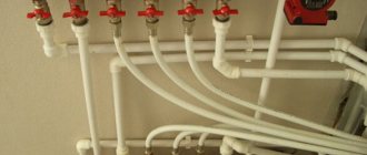
To limit the entry of foreign objects into smoke exhausters, special
suction pockets , which are connected to the suction pipes of the smoke exhausters.
An example of a suction pocket for a smoke exhauster is shown in the photo on the left. Single-suction centrifugal blower fans of the VDN type are designed to supply air to the furnaces of steam boilers. Such fans are equipped with balanced draft boilers with a steam output of 1…25 t/h, as well as gas-oil water heating boilers with a heating output of 0.5…16 Gcal/h.
It is allowed to use blower fans in technological installations in various sectors of the national economy to move clean air, as well as as supply smoke exhausters on gas-oil boilers with balanced draft.
Blower fans are designed for operation at ambient temperatures not lower than -30oC and not higher than +40oC; the maximum permissible temperature of the transported medium at the fan inlet is +200oC. Blower fans are designed for long-term operation indoors and outdoors (outdoors under a canopy) in moderate climate conditions (climatic version U, placement category 2, GOST 15150-69). The permissible ambient temperature is not lower than -30oC and not higher than +40oC.
Principle of operation
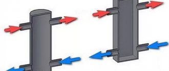
By their type, blower fans and smoke exhausters are centrifugal machines, therefore their operating principle is similar to the operating principle of centrifugal pumps. They work as follows. The rotation of the motor drives the impeller. Rotating, the latter creates a vacuum in the center, under the influence of which air or flue gases are drawn through the suction pipe into the pump housing. Thrown by the wheel blades to the periphery, it flows through the spiral casing into the discharge pipe, creating increased pressure in it.
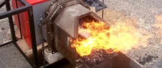
Depending on the type of fuel being burned, the blower fan discharge pipe is connected to the burner (if heating is produced by gas or liquid fuel) or to the primary air supply input to the boiler - under the grate (if solid fuel is used). Passing through the ash and combustion chamber, the air supplies the firebox with a sufficient amount of oxygen necessary for complete combustion of the fuel.
Fans (smoke exhausters) are designed for operation at outside temperatures of -40… +40 °C. The permissible temperature of pumped gases for fans depends on the modification and is -30...200 °C (for VD models) or -30..80 °C (for VDN). Operation of smoke exhausters is allowed at temperatures of exhausted gases up to 250 °C.
Smoke exhausters and blower fans should not be used for pumping explosive and aggressive gas-air media, mixtures that are highly dusty, and/or containing adhesive, fibrous or abrasive substances.
Main characteristics
The main characteristics that determine the operation of a centrifugal fan are:
- performance, that is, the ability of the fan to pump a certain amount of gas-air mixture per unit of time, m³/hour;
- total pressure, the pressure created by the fan at its outlet, taking into account the pressure at the inlet.
Fan selection
A blower fan is selected with a lower capacity than a smoke exhaust fan, since the amount of combustion products exceeds the required amount of supplied air, and the boiler furnace must be under vacuum (the draft created by the smoke exhauster exceeds the excess pressure created by the blower fan. The choice of a fan for smoke exhaust depends on the power of the boiler with which it will be used to be used, depending on the cross-section and length of the chimneys, and the type of fuel used in the boiler plant.
Options for draft machines
There are 5 design options for draft machines, depending on the installation diagram (method of connection to the engine, type of frame and base). In some cases, a vibration base is used to reduce vibration. Features of the wiring diagram for each version are shown in the table below.
| Execution | Working wheel | Frame | Base | Suction |
| 1 | Mounted on shaft | Engine frame or general | Normal | Unilateral |
| 2 | a) Installed on the motor shaft b) Installed on the intermediate shaft (bearing unit) | a) Single with the engine b) Common base (pedestal) | Vibration base | Unilateral |
| 3 | Installed on the intermediate shaft (bearing unit) | a) Separate (separate for motor and fan) b) Single a) Common base (pedestal) | Normal | Unilateral |
| 4 | Impeller with forward curved blades | Separate for motor and fan | Normal | Bilateral |
| 5 | Impeller with radial or backward curved blades | Separate for motor and fan | Normal | Bilateral |
Blower fans
| ← Smoke exhausters | ↑ Contents | Gas-air duct Chimneys → |
Section contents [
+
] Boiler room draft equipment
Blower fans are designed to supply air to the furnaces of boiler units. The permissible ambient temperature is not lower than –30°С and not higher than +40°С.
JSC BiKZ produces centrifugal single-suction blower fans of the VDN type, designed to supply air to the furnaces of steam and hot water boilers for burning all types of fuel.
The fans are equipped with balanced draft boilers with a steam output of 1…25 t/h, as well as gas-oil water heating boilers with a heating output of 0.5…16 Gcal/h.
It is allowed to use fans in technological installations in various sectors of the national economy to move clean air, as well as smoke exhausters on gas-oil boilers with balanced draft.
The technical characteristics and aerodynamic parameters of the fans produced by BiKZ OJSC are given in [Table] 6.1.5 (Fig. 6.1.9-6.1.10), 6.1.6, and the performance, total pressure and power consumption correspond to operation with a fully open guide vane path with a characteristic passing through the point of maximum efficiency (83%), atmospheric pressure (760 mm Hg) and air temperature 30 °C (density 1.18 kg/m3).
Fans VDN-12.5; VDN-11.2; VDN-10; VDN-9 and VDN-8 (Fig. 6.1.8) were developed by JSC BiKZ according to the aerodynamic design 0.55-40o-1 MO TsKTI (VNIIAM). The main components of VDN type fans are the impeller, volute, suction pipe, axial guide vane and pedestal. The impellers of right- and left-hand rotation fans consist of a welded impeller and a hub. The fans are made without an autonomous running gear with direct mounting of the impellers on the shaft of the electric motor-drive (see Fig. 6.1.8). The hubs of the fan impellers have splined grooves, which makes it possible to use the fans as smoke exhausters on gas-oil boilers. Fan volutes are welded from sheet and profile steel. To create the necessary rigidity, the end walls of the snails are reinforced with strip fins. Fans are supplied to the customer with a volute rotation angle of j = 180°; when supplied for export – j = 0, 90, 180 and 270o. If necessary, it is possible to install volutes with any rotation angles from 0 to 270° every 15°.
The VDN-8.5 fan is a high-pressure, centrifugal fan, designed to supply clean air to the furnaces of boilers with a low-temperature fluidized bed. The fan can operate at a temperature of the transported air not lower than –30° and not higher than +40°.
The fan consists of a housing, an impeller, a drive unit with an electric motor and a guide vane (Fig. 6.1.11). The fan is manufactured in right and left rotation. The welded housing can be installed with different angles of rotation of the discharge pipe from 0 to 270° every 15°.
Technical characteristics of the high-pressure fan are given in table. 6.1.7.
Data on special smoke exhausters and fans are presented in table. 6.1.8 – 6.1.12 [7].
Table 6.1.5
Weight and aerodynamic parameters of fans at an air temperature of 30°C
| Fan designation | Productivity, 103 m3/h | Total pressure, Pa | Power consumption, kW | Weight, kg, no more |
| VD-2.8 (1500) | 1,3 | 700 | 0,4 | 88 |
| VD-2.8 (3000) | 2,6 | 2800 | 3,3 | 103 |
| VDN-6.3 (1000) | 3,4 | 625 | 1,05 | 395 |
| VDN-6.3 (1500) | 5,1 | 1380 | 2,4 | 395 |
| VDN-6.3 (3000) | 10,2 | 5530 | 19,2 | 395 |
| VDN-8 (1000)* | 6,97 | 900 | 2,3 | 498 |
| VDN-8 (1500)* | 10,4 | 2230 | 7,9 | 527 |
| VDN-8 (3000)* | 16,0 | 1000 | 54,5 | 1722 |
| VDN-8 RP from 0 to 3000 min-1 | 10,46 | 2230 | 7,9 | 559 |
| VDN-8.5 (3000)** | 28,0 | 1000 | 93,0 | 1361 |
| VDN-9 (1000)* | 9,93 | 1250 | 4,2 | 548 |
| VDN-9 (1500)* | 14,9 | 2830 | 14,2 | 574 |
| VDN-10 (1000)* | 13,62 | 1550 | 7,1 | 690 |
| VDN-10 (1500)* | 20,43 | 3520 | 24,0 | 723 |
| VDN-11.2 (1000)* | 19,13 | 1940 | 12,6 | 1026 |
| VDN-11.2 (1500)* | 28,7 | 4410 | 42,5 | 1080 |
| VDN-12.5 (1000)* | 26,6 | 2430 | 21,8 | 1354 |
| VDN-12.5 (1500)* | 39,9 | 5520 | 73,6 | 1410 |
| VDN-13 (1000)* | 40,0 | 2270 | 34,0 | 1475 |
| VDN-13 (1500)* | 60,0 | 5100 | 116,0 | 1811 |
| VD-30-85 TS (30TSO-85R) | 3,0 | 8330 | 13,0 | 204 |
| VD-19-63 TS (19TSO-68) | 1,9 | 6180 | 6,0 | 149 |
| VDN-15 (1500) | 77,5 | 8800 | 218 | 3434 |
| Entrainment return fan 3000 min-1 | 1,0 | 3800 | 1,7 | 112 |
| Sharp blast fan, 3000 min-1 | 1,8 | 3950 | 3,5 | 128 |
| V-0.6-300-6.6 (axial) | 10,5 | 172 | 0,6 | 60 |
Table 6.1.6
Technical characteristics of VDN type fans[edit]
| Indicator name | VDN-12.5 | VDN-11.2 | VDN-10 | VDN-9 | VDN-8 |
| Impeller diameter, mm | 1250 | 1120 | 1000 | 900 | 800 |
| Rotation speed, min-1: | |||||
| maximum | 1500 | 1500 | 1500 | 1500 | 1500 |
| nominal | 1480 | 1480 | 1480 | 1480 | 1480 |
| Aerodynamic parameters at a gas density at the fan inlet of 1.18 kg/m3: | |||||
| productivity, thousand m3/h | 39,9 | 28,7 | 20,4 | 14,9 | 10,5 |
| total pressure, Pa | 552 | 441 | 304 | 283 | 223 |
| shaft power, kW | 73,6 | 42,5 | 21 | 14,2 | 7,9 |
| Maximum efficiency,% | 83 | 83 | 83 | 83 | 83 |
| Overall dimensions at j =90о, mm, no more: | |||||
| length (along the shaft) | 1751 | 1517 | 1366 | 1214 | 1176 |
| width | 2050 | 1843 | 1651 | 1491 | 1331 |
| height | 1885 | 1690 | 1506 | 1360 | 1210 |
| Weight (without electric motor), t, no more | 1,41 | 1,08 | 0,73 | 0,57 | 0,52 |
[[Image:]]
Rice. 6.1.8. Single-suction centrifugal blower fans VDN-12.5; VDN-11.2; VDN-10; VDN-9 and VDN-8 at j = 90o: 1
- snail;
2
- removable diaphragm;
3
- pedestal;
4
- axial guide vane;
5
- suction funnel;
6
- impeller;
7
— drive electric motor (chassis). (Dimensions in table 6.1.6)
[[Image:]] [[Image:]]
Rice. 6.1.9. Aerodynamic characteristics of fans VDN-11.2 and VDN-10 at a rotation speed of 1500 min-1
[[Image:]] [[Image:]]
Rice. 6.1.10. Aerodynamic characteristics of fans VDN-9 and VDN-8 at a rotation speed of 1500 min-1
[[Image:]]
Rice. 6.1.11. High-pressure centrifugal fan VDN-8.5
Table 6.1.7[edit]
Technical characteristics of high-pressure fan VDN-8.5
| Suction capacity, m3/h | 28000 |
| Total pressure, Pa (kgf/m2) | 10000 (1000) |
| Maximum efficiency,% | 83 |
| Rotation speed (synchronous), min-1 | 3000 |
| Nominal power consumption, kW | 92 |
| Impeller diameter, mm | 850 |
| Density of the transported medium at a given suction pressure and temperature, kg/m3 | 1,2 |
| Overall dimensions, mm: | |
| length L | 2848 |
| height | 1285 |
| width | 1375 |
| Weight, kg | 1722 |