What is a "lining"?
Furnace lining is the installation of a facing layer on the internal planes of the combustion chamber, which are in constant contact with open fire. Its function is to protect external walls from damage of a thermal, mechanical, chemical or physical nature. Lining is performed not only for heating devices for domestic use; this technology is used in the manufacture of metallurgical smelting furnaces, steam boilers, ladles, etc.
In addition to fire protection, heat-resistant material performs a thermal insulation function - reducing heat loss. However, there is some danger here: a lining layer that is too thick will lead to a decrease in the efficiency of the device, since the flow of thermal energy will “fly away” through the chimney to the street, rather than spreading inside the room.
Methods of execution
Furnace bunkers are lined, depending on the building material of the main structure, in several ways:
- installation of a facing layer made of materials with a low thermal conductivity coefficient: fireclay bricks or special panels. This work can be done both during the construction of the stove and after its construction is completed;
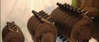
Fireclay brick
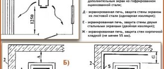
- installation of protective screens that reflect thermal radiation. It is used for lining metal stoves - heaters, which are used to equip steam rooms in baths. The use of heat-reflecting screens for other designs of heating units is ineffective;
- coating the inside walls of the combustion chamber with a heat-resistant mixture of various types. You can apply the composition to the walls of the firebox at any time - during construction or in a ready-made unit.
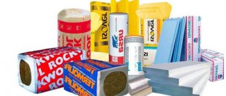
Materials used
Refractory materials for lining furnaces, depending on the ingredients included in the raw material composition, are divided into the following classes:
- A - products based on materials of natural origin or a synthetic composition with the addition of an organosilicon binder;
- B - a special type of clay (fireclay) is used as the main ingredient;
- C - other components of refractory substances.
Products and compositions for lining a class B furnace (bricks, blocks, mastics, etc.), the basis of which is fired fireclay clay, are available, inexpensive, and therefore are most popular. To increase heat resistance, portions of quartz sand, sandstone and other types of rocks, the strength of which remains unchanged at any heating temperature, can be introduced into the raw materials during their production.
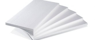
As additional protection, materials in the form of a roll, plate or sheet are used for fireclay products. They are laid between layers of masonry made of heat-resistant and ceramic products. The list of such materials for furnace lining, which are based on white clay, includes:
- basalt wool;
- dense kaolin;
- mullite - siliceous mats;
- vermiculite and a number of other products.
Dry mixtures are used to make fire-resistant mortar, which is used to coat the surfaces of the combustion bunker and other masonry elements. They fill the cavities of technological clearances and gaps that compensate for the linear expansion of the structural parts of the metal furnace.
Refractory materials for lining furnaces also include heat-resistant aluminosilicate adhesive mass, which is used to glue refractories in sheet or roll form. This glue is also used for fireclay masonry and for coating walls made of bricks with low heat resistance with a thin layer.
Pros and cons of different lining materials
In small laboratory structures, refractory materials for lining furnaces occupy the entire space of the working chamber. Let's look at each variety in more detail and list their advantages and disadvantages.
Corundum or ceramics
Dense and hard material, resistant to aggressive chemicals. Very strong and durable. Among the disadvantages of muffle furnaces with a ceramic chamber, we note:
- Significant time costs to achieve the desired heating temperature.
- Increased power.
- The cost is half that of a fiber muffle.
The ceramic stove will serve for many years without compromising the integrity of the chamber
Fiber
Made from aluminum oxide, it heats up very quickly. Disadvantages include the inability to work with samples containing liquids. The vapors and gases released may render the camera unusable. In addition, aluminum fibers are considered very fragile and require careful handling. Once the surface inside the muffle is damaged or worn, further operation is impossible.
Fiber construction price is lowest
Ceramic fiber
Combines the best qualities of the two materials described above. With less power input, heating occurs much faster. The material is also characterized by average resistance to various chemicals.
When using a ceramic fiber muffle, the temperature regime must be strictly observed and not exceeded
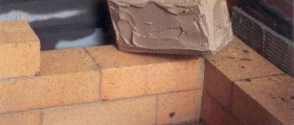
Is it necessary to soak fireclay bricks before laying?
Even experienced stove makers do not have a clear answer to this question. However, having studied the physical properties of fireclay, you can be convinced that in some cases, before making the furnace lining, it is simply necessary to moisten the masonry material:
- when the masonry is done with used bricks. During previous use, the pores of the material became clogged with particles of dust and masonry mixture, and in order to open the capillaries in its structure, the brick is soaked. After the brick is removed from the container with water, you should wait until all the liquid has drained from it, and only then use it for masonry work;
- when building a heating device in the summer heat, but with high humidity in the fall or spring, it is better not to soak the brick.
Glue and solution
Refractory mortar for laying fireclay bricks
In addition to the quality and characteristics of materials, the effectiveness of the lining procedure is also influenced by their correct installation using special substances.
Solution
Heat-resistant solutions form a monolithic thin layer on the walls of the firebox, protecting the working surface from the effects of flame. Such a monolith may require repairs as it wears out. When working with the solution, you must follow the basic rules:
- Solutions are prepared from dry mixtures of corundum, mullite or fireclay type, which are diluted with water to a creamy consistency. The proportions of the components and the characteristics of the mixtures are usually indicated on the packaging.
- First, the solution layer is fired with a blowtorch or heated in an oven until a hard coating forms during firing.
- If the lining is carried out using fireclay bricks, the joints must be filled to the full height of the masonry.
For 1 m3 of brickwork, at least 100 kg of ready-made mortar from any type of mixture is usually required.
Fireproof glue
Fireproof adhesive for laying out the firebox
Instructions depending on the material
A layer of cardboard between the inner and outer layers of masonry
It is better to entrust the lining of a standard or induction furnace to specialists, but if you have minimal skills, you can carry out this procedure yourself, following the rules.
Brick oven
When lining the combustion chamber of a brick kiln, the thermal expansion of the material is taken into account. Between the internal protective and external standard layer of masonry, you need to leave a gap of 7-10 mm or supplement it with a gasket made of kaolin, basalt or asbestos cardboard.
Metal oven
Lining a metal furnace
The procedure for metal furnaces is carried out in the same way as for brick equipment. It must be taken into account that there must be a gap between the metal wall and the material to compensate for linear expansion. This space can be filled with basalt or kaolin slabs or asbestos sheets.
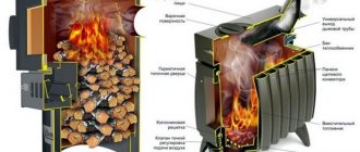
Solid fuel stove
For solid fuel stoves, it is advisable to carry out lining using one of the three available methods. Heavy lining is carried out for furnaces with weak shielding; with this method, the lining is carried out with masonry in two or three layers. In the case of lightweight lining, the masonry should be single-layer. There is also an option for pipe lining, when the boiler pipes are coated with fire-resistant glue on the outside.
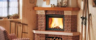
Clay oven
Fireboxes in clay ovens are recommended to be lined with fireclay bricks or coated with plastic refractory materials, for example, mastic or aluminosilicate glue. After hardening, the layer of such material is a dense shell that protects the walls from overheating.
Fireclay brick
Lining with fireclay bricks is carried out by laying out the material in several rows with a slope and an edge with a shift of up to 1/2 of the length towards the block in the bottom row up to the top of the combustion compartment. The upper plane is faced last, laying the bricks flat. It must be remembered that the lining layer and the main masonry of the walls must correspond to each other in the location of the vertical seams.
Schemes of tube furnaces
Below are common diagrams of domestic tube furnaces.
Furnaces type SS
Furnaces type SS are sectional with a horizontally located coil, a free-standing convection chamber, a built-in air heater and free vertical flare combustion of fuel. The pipe coil of each section consists of two or three transportable factory-made packages. The coil of each section is self-supporting and is installed directly on the furnace floor.
Furnaces of the CS type are cylindrical with a wall arrangement of coil pipes in one radiation chamber and free vertical flare combustion of combined fuel. Ovens are made in two versions: without a convection chamber and with a convection chamber (Fig. XXI-12).
By the way, read this article too: Nozzles and burners
The cylindrical radiation chamber is installed on a columnar foundation for ease of maintenance of gas burners located in the hearth of the furnace. The radiant coil is assembled from vertical pipes on welded rolls; A gas-oil burner is installed in the center of the furnace hearth. The coils rest on the underside of the oven, and the product enters and exits from above.
Furnace type CD4
Furnace type TsD4, a longitudinal section of which is shown in Fig. XXI-13, is a radiant-convection type, in which along the axis of the radiation chamber there is a divider-distributor in the form of a pyramid with concave edges, which represent the floor walls for the burner torches installed in the hearth of the furnace.
The divider-distributor divides the radiation chamber into several independent heat exchange zones (see Fig. XXI-13, there are four of them) with the aim of possibly adjusting the heat intensity along the length of the radiant coil. The internal cavity of the divider frame is divided into separate air ducts; in the masonry of the divider face along the height of the face there are channels of rectangular cross-section for supplying secondary air to the flat torch of each face. Each air duct is equipped with a rotary damper controlled from the service platform.
In the masonry of the divider faces, on two tiers along the height of the faces there are rectangular cross-section channels for supplying secondary air from the air ducts to the flat torch of each face. By changing the air supply through the channels, it is possible to regulate the degree of fuel burnout in the flat torch, which makes it possible to equalize the heat intensity along the height of the pipes in the radiation chamber.
The radiant suspension coil consists of pipes located at the walls of a cylindrical chamber. Wall-mounted radiant pipes are placed in one row and have one-sided irradiation, while radial pipes with double-sided irradiation are placed in two rows.
Furnaces type KS
Furnaces of the KS type are cylindrical with an annular convection chamber, a built-in air heater, vertical pipe coils in the radiation and convection chambers and free vertical flare combustion of fuel (Fig. XXI-14). Combination burners are located in the hearth of the furnace. A single- or double-row wall-mounted pipe screen is installed on the walls of the radiation chamber. The convective coil, like the air heater, is assembled in sections and placed in an annular convection chamber installed coaxially with a cylindrical radiant chamber.
Furnaces type KD4
KD4 type furnaces are cylindrical four-section with an annular convection chamber, built-in air heater, differential air supply along the height of the torch, vertical arrangement of the coil of radiant and convection pipes, flat combustion of combined fuel. Stoves are made in two designs: with a chimney installed on the stove or standing separately.
Manufacturing lining and material properties
In production, in metallurgy, the lining of an induction furnace is made using special, pressed fireclay bricks. They are very wear-resistant, do not shrink and withstand thermal shocks well. The use of fireclay bricks made it possible to achieve great cost savings and greatly reduce the cost of the metal production process.
Induction oven
Induction oven
The table shows the properties of some refractory materials
| Material | Density kg/m3 | Maximum operating temperature °C |
| Chamotte | 1800-2000 | 1300 |
| Clay brick | 1600 | 700 |
| Vermiculite | 150-250 | 1100 |
| Basalt wool | 100 | 750 |
| Kaolin is dense | 2400-2500 | 1400 |
Household problems - lining as a solution
In everyday life, people usually have to solve simpler problems. At the very last stage, the burning of the coals, the bottom of the metal stove overheats, sometimes red hot. A man decides to cover the overheating wall from the inside with his own hands.
But even in this case, you have to decide to what level to lining, whether to leave a gap and how to secure the bricks?
Specifically in this situation, the issue can be resolved as follows:
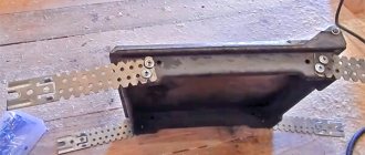
- If the width of the firebox allows, fireclay bricks of a standard size are laid along its perimeter - 250X150X65 mm. In this case, the brick is laid flat against the wall. Can be laid vertically with a height of 250 mm or horizontally with a height of 120 mm.
- In order to securely fix the bricks together, a simple method is used. Using a grinder, a cut is made in part of the joint, and the bricks are held together using an inserted metal spike of a suitable size.
Lining device: temperature and metal
Particular attention should be paid to the fact that the thermal linear expansion of metal is much greater than that of brick. Therefore, all metal parts exposed to heat must have free space for expansion.
Our information: the absence of a gap between the metal wall of the furnace and the lining leads to destruction of the lining.
When installing this lining, the gap is sealed with basalt or kaolin wool, twisted into bundles, cords or in the form of a compressed sheet. Asbestos can be used for this purpose.
Wrong defense. Consequences
This picture occurs very often. The metal stove is lined with bricks using clay mortar, and without any gap. This is motivated by ensuring safety and improving the heating of the furnace.
Types of repairs of brick stoves and fireplaces
Maintenance
The works of this group include those that are small. They are necessary, and most importantly, can be completed in the shortest possible time. The urgency of performing such work is due to the fact that untimely elimination of these deficiencies leads to the occurrence of more serious malfunctions. And those, in turn, can lead to a fire or accident. These types of work include: replacing valves, grates, doors, individual bricks, strengthening tiles and sealing cracks.
In order to strengthen the door, it must first be removed from the masonry along with the frame. After this, they are replaced with new mounting tabs. At the attachment point, the masonry is cleared and then moistened with water before reinstalling the door. When installing, make sure that the door frame tabs fit into the masonry joints. After this, the seams are clogged with mortar. If there are cracked bricks, they should be replaced with new ones. The gap between the stove masonry and the door frame is sealed with asbestos cord (5 - 10 millimeters). Having secured the frame, the identified cracks are rubbed or covered with clay mortar.
The failed grate is removed, then the place where it was installed is cleared of accumulated ash and a new one of the same size is placed there. Do not forget that there should be a gap of at least 5 - 10 millimeters around the perimeter of the installed grate (to compensate for the difference during temperature expansion). Which is clogged with sand or ash. If cracks are found in the masonry joints, you should clean them to a depth of 30 millimeters, moisten them with water, then hammer them with masonry mortar and rub them in place.
If cracked bricks are identified in the masonry, they should be removed, the place where they stood should be cleared of any remaining mortar and moistened thoroughly. The new brick is also wetted and installed in the opening using clay mortar. The seams, if necessary, are coated with a solution and then rubbed down.
Minor repairs to the lining, as well as the walls of the firebox, are carried out through the firebox door. Identified damaged areas are cleared and coated with a solution made on the basis of refractory concrete or refractory clay. If there are broken bricks in the lining, they are removed, the place where they are installed is cleared, and a new brick is installed there. In this case, you should use exactly the solution with which the lining was carried out.
The steel sheets placed in front of the firebox are deformed during their operation. there is a possibility that coals caught on them may cause a fire. To avoid this, the failed sheet is torn off, the fastening nails are removed, and the underlying asbestos sheet is replaced (an option is double felt soaked in a clay solution). And a new sheet of roofing iron or steel is laid on top and nailed.
Cracks identified in the tiled masonry should be repaired with gypsum, best of all, after mixing it with aluminum-potassium alum. Another option is chalk, which is mixed with raw egg whites. In those cases. when several defects are simultaneously detected in one tile, it is best to change such a tile. The new one is pre-selected according to pattern and color, and then adjusted to size. After this, the old one is removed and the place where it is installed is cleared. The pump of the selected tile is filled with mortar, which is mixed with fragments of broken brick, then it is installed in place. The strength of the repaired area will definitely be lower than that of the main masonry, since you will not be able to connect the installed tile with wire to the adjacent tiles.
Cleaning dirt that appears on tiles is quite simple. Wipe the entire surface of the masonry with a damp cloth. Then prepare gypsum dough, brought to a creamy state, and apply it to the tiles in a thin layer. Then the setting plaster along with the dirt is removed with a dry cloth.
Medium renovation
At this stage of repair work, more significant damage is eliminated. These include (the list is incomplete): replacement of lining walls, clearing of debris formed in smoke ducts, repair of pipe walls and fireboxes, etc. The above-mentioned blockages can occur due to poor dressing of seams during the laying process, the use of poor quality bricks, long service life of the kiln, etc. You can determine that there is a blockage and determine exactly where it is by using a wire for this purpose that is passed through the cleaning holes.
If the location of the blockage is not determined in this way, or the identified blockage cannot be broken through, then you will have to dismantle the masonry of the wall. pay attention to that. that the surface of the hearth is subject to abrasion during operation, so it should also be periodically repositioned. This is done as follows. The old hearth masonry is removed, then the base is leveled with its obligatory slope towards the rear wall of the chamber. A new layer of hearth is laid from the hearth towards the rear wall.
After replacing the hearth, it should be sanded using sand and brick for this purpose to eliminate any unevenness. The cracks that may form between the bricks must be filled with ash or fine sand.
During operation, destruction also begins at the pipe heads. Repair of chimneys and their caps is carried out using high-quality, well-fired bricks. The destroyed part of the chimney is dismantled, the masonry is cleared and moistened with water. Then. using cement or mixed masonry mortar, a new head is laid out. In this case, special attention should be paid to the quality of suture dressing. The upper part of the chimney is leveled. Using cement mortar for these purposes, a bevel is formed to its outer walls.
Major renovation
This category of work is the most difficult. The stove cannot be heated while they are being performed. During a major overhaul, the following repair work may be performed:
Alteration of the firebox (for example: it had a blind pan, now it has a ash pan and a grate);
Replacement of the furnace lining and fire duct;
Conversion of the combustion chamber, designed for the use of firewood, into a firebox for coal;
Replacing the smoke circuit diagram, etc.
Carrying out all of the above work requires preliminary disassembly of one or two walls of the furnace, or its complete disassembly.
Thus, work on replacing the firebox lining is carried out after the furnace wall is dismantled to the height of the firebox (counting from the base of the ash pan). If it is also planned to rework the chimneys, then the furnace wall will have to be dismantled to the ceiling. Lining is carried out without tying the masonry to the main brickwork of the furnace. The order of work is as follows. The furnace wall is dismantled. Then the old lining is dismantled and the walls are cleaned of debris and mortar residues. Then a new lining is made using refractory mortar. We don’t change its thickness, a quarter of a brick. The option of laying a brick lining in the floor is possible (the choice depends on what kind of masonry was previously used). we remind you. That the thickness of the seams when laying the lining should not be more than 3 millimeters.
To remodel the chimney, you should completely disassemble it at the first stage of work. For a new chimney, orders are first made (with obligatory consideration of the previous dimensions). The masonry is carried out by tying it with the masonry of the stove itself.
To eliminate the possible appearance of condensation, one or two chimneys are completely plugged or dismantled. A simpler option is to make a square window with a side of 50 millimeters between the firebox and the chimney. Such windows are most often made in the last chimney. Less often – also in the penultimate one. The best results are obtained in cases where one or more chimneys are first shut off, and only then are those in which it is advisable to make holes (windows) determined. To perform the above work, you will first need to disassemble the walls of the furnace (in their upper and lower parts). Subsequent restoration of dismantled areas requires very careful work.
In the case when an existing firebox with a blind tray is converted into a firebox, which will have a grate and a vent, the work is performed in the following sequence.
If the base of the stove is separated from the hearth by five or more rows of masonry, the fire door can be left where it is installed. If there are fewer of them, then the door will have to be dismantled and reinstalled several rows higher. In this case, you should remember the basic figures: the firebox for wood should have a minimum height of 500 - 550 millimeters, for coal: 400 - 450 millimeters. In cases where it is planned to use anthracite or coal as fuel, it is highly desirable that the door be sealed (both ash and combustion). Holes with a diameter of 10 to 15 millimeters are drilled in the views (latches). New grates for coal are installed, heavier, but of the same size.
Sequence of work. The door is removed and the front wall is disassembled. Understands under. Garbage is removed. The blower is made, the grates and the blower door are installed, and the combustion door is secured. The hole in the wall is sealed with control over the ligation of the seams.
If the existing furnace is so large that two can be made from it, you can separate it as follows. The dimensions of future structures and a list of upcoming work are determined (with calculations of the materials required for this), then one of the side walls is dismantled. Most often, when performing separation work, new furnaces are made with independent smoke circulation and fireboxes. Then, in the area of the ceiling, these pipes are combined into a single pipe. In cases where this is not possible, each furnace has its own chimney.
In addition to those discussed above, other work may be performed during a major overhaul. For each of them, it is first necessary to think through the sequence of their implementation and prepare the required tools and materials in advance.
Metal lining
The lining of a metal furnace is done only from the inside. Additional external cladding or coating of the stove will speed up its warming up, but, contrary to popular belief, it will have almost no effect on the thermal efficiency of the stove: the rule of insulating rooms “from the cold side” arose because the dew point cannot be allowed into the room; for a lined furnace it is not relevant. But the outer lining/coating of the furnace will greatly increase the thermal stresses in the metal of its body and its sensitivity to chemical influences.
It is best to line a metal stove with vermiculite using ScannMix glue or its analogues: the packaging or specification of the glue should indicate that it glues both metal and/or ceramics to metal (if it glues ceramics to metal, it will also glue slab materials). For good thermal insulation of a muffle furnace, a vermiculite plate 20-30 mm thick is sufficient. If a metal stove is lined with brick, then it must be installed according to the same rules as in the firebox of a brick stove. For example, how a gas forge furnace is lined with fireclay, see video:
shotcrete
Shotcrete, which our company offers as a binder, includes better adhesion to the surface, less kickback, quick drying, no cracking due to exposure to high temperatures, shows long-term durability, which is usually twice as long as materials with cement in as a binder.
Conventional shotcrete materials are transported dry under compressed air pressure and mixed with water in a nozzle during unloading. The amount of water (binder) and, as a result, the viscosity of shotcrete completely depends on the skill and skill of the technician using the shotcrete. Low cement content refractories used as shotcrete also contain added water and therefore must be dried and heated before use and are thus susceptible to cracking.
Shotcrete-based materials are prepared as a slurry/slurry using a precisely measured amount of colloidal silica binder (without adding water). The slurry is then pumped into a special nozzle where the technician can add an accelerator during use if needed to optimize adhesion to the target material depending on the ambient temperature and conditions. The unique colloidal silica binder system does not require special drying or heating, unlike cement-based binder products.
When dry, shotcrete-based materials adhere strongly to existing refractory materials as a binder, ensuring long-lasting use. Their inherent resistance to thermal cracking ensures that the profiling lining is fully intact at start-up, providing additional potential for long-term use. Shotcrete binder materials minimize downtime and increase useful time by eliminating long drying periods.
Design
Let's consider the design using the example of a radiant-convection oven . The furnace is a double block of two vertical flare type furnaces united by a common chimney installed on a ceiling frame.
Frame
The load from the weight of chimneys, doubles, roofing of platforms and stairs in most structures is carried by a frame consisting of racks, trusses and connecting elements. Depending on the size of the furnace, one or another frame system is adopted.
By the way, read this article too: Cylindrical furnaces type TsS
The frame of each of the furnaces included in the block is made in the form of a 6-span spatial structure consisting of U-shaped frames installed on foundation supports and interconnected by vault and bottom frames.
Rice. 3 – General view
The frames of both furnaces are connected by horizontal beams along the height of the radiant chambers, and by the end beams of the ceiling frame. The chimney is installed with a damper on the ceiling frame.
The frame is always protected from excessive overheating by using thermal insulation or leaving gaps between the frame post and the lining.
Coil
The heated product moves in a coil located in the oven. The coil consists of pipes and connecting parts. There are single-flow, double-flow and multi-flow coils.
Connecting parts - twins (returbends ) and rolls make it possible to clean the internal surfaces of the pipes from salt deposits and various contaminants, inspect them and measure the thickness of the pipe walls in various places of the coil.
If there is complete absence of contamination of the inner surface of the coil and there are reliable methods for controlling the thickness of the pipe wall, it is possible to use an all-welded coil (without returbends).
The coil is made of smooth, seamless pipes with a wall thickness of 4 to 30 mm , depending on temperature, pressure and diameter. Some convection ovens use thick-walled alloy steel tubes with carbon steel fins for destructive hydrogenation to increase the heating surface.
When choosing a pipe material, you need to take into account the temperature difference when heat is transferred through a number of thermal resistances. During operation of the furnace, these resistances do not remain constant and at some period the temperature of the pipe wall rises to a certain limit, when further operation can lead to an accident.
In this example, all raw coils are horizontal type. The radiant and convective coils of each furnace included in the unit are 4-flow . Radiant coils are located along the front walls of the radiant chambers, one flow from each front. Flow direction is from bottom to top.
Fig. 4 – Furnace coils
Three blocks of convection pipes are installed on the vault frame . The convective coil pipes are placed in the block in a checkerboard pattern. The coil inlet and outlet pipes are sealed in end panels and covers, as well as in end convection grilles.
Tube sheets
Tube sheets are supports for the product coil pipes.
Tube sheets, washed by flue gases with temperatures up to 800 ° C, are made of gray cast iron grade SCh 21-40, and sometimes from sheet steel.
Tube sheets, which are washed by flue gases with temperatures up to 1000 ° C, are made of heat-resistant cast iron, and at temperatures above 1000 ° C they are of the EI-316 grade. The thickness of the castings is recommended to be at least 20 mm. Asbestos cardboard 5-6 mm thick is placed under each pipe at the point of contact with the grating.
Depending on the number of supported pipes, the tube sheets of the radiant section are divided into two-, three-, four-, five- and six-tube. The gratings are covered with a layer of thermal insulation.
Pipe hangers
Tube hangers support the radiant tubes in the span between the tube sheets and prevent them from sagging.
By the way, read this article too: Types of Tube Furnaces
Pipe hangers are installed inside the combustion chamber, where the temperature of the flue gases reaches 1100° C.
Panels
The lining is made in the form of a panel. Each panel consists of a five-millimeter sheet box reinforced with stiffening ribs with sides filled with light heat-resistant concrete prepared from a dry mixture of high-alumina cement with vermiculite-expanded clay filler.
Fig. 5 – Oven panels
Burners
The boxes are hermetically welded around the perimeter to each other and to the frame. Each furnace has 12 oil-gas burners . Each main burner is equipped with flame presence indicators and a permanently operating pilot burner.
12 peepholes installed on the front walls, . At each end of each furnace of the block there are manhole doors and one explosion valve - an explosion window.
Window
safety window - designed to reduce the force of an explosion, as well as for inspection of the combustion chamber. Frames and doors are made of gray cast iron SCh 15-32, the axis is made of steel grade St. 3.
Inspection window - used to monitor the burners during the operation of the furnace and the condition of the radiant section pipes. The material of the body and cover is gray cast iron SCh 15-32, the handles and axles are steel grade St. 3.
Shiber
The gate serves to regulate traction. The material for the gate blade is gray cast iron SCH 15-32.
Stairs and landings
The system of stairs and service platforms includes: three tiers of closed platforms around the furnace block, 5 tiers of end platforms for servicing blocks of convection chambers and end peepholes. The main platforms are connected by flights of stairs.
Fig. 6 – Staircase system
Fireproof materials for the protection of boiler and economizer pipes
| Product: | coating of pipes in furnaces with liquid slag removal and waste incineration plants. |
| Type: | pin pipe mass |
| Main raw materials: | silicon urea |
| Type of application: | inorganic/chemical or binding |
| Max operating temperature: | 1750°C for furnaces 1550°C for waste incinerators |
| Material requirement: Bulk density: | 2.65 t/m3 2.58 g/cm3 |
| Max. particle size: Water requirement: | 2 mm 0-0.2 l/100 kg |
| Bond Requirement: Open Porosity: | 5.5 kg/per 100 kg weight 19% |
| Irreversible change in length: Reversible change in length: | — 0.04% / 800° С 0.7 % / 1000° С |
Chemical composition
SICAl2O3SiO2Fe2O3CaONa2O3MgO
| 85,0 | 6,3 | 4,2 | 0,09 | 0,04 | 0,08 | 0,03 |
Physical properties
Cold compressive strength N/mm2 Compressive strength N/mm2 Cold bending strength N/mm2 Pre-drying/firing ° C Thermal conductivity W/mK Temperature ° C
| 35 | 9 | 110 | 8,5 | 400 | |
| 55 | 45 | 12 | 200 | 8,5 | 600 |
| 75 | 55 | 18 | 400 | 8,5 | 800 |
| 85 | 65 | 600 | 8,5 | 1000 | |
| 95 | 75 | 800 |
Storage:
Unlimited in a cool and dry place.
Smallest Deliverable Unit:
disposable pallet.
Package:
PE bag
Induction furnace lining
The lining of induction crucible furnaces (see Fig. 1) consists of 6 main elements: crucible, hearth, collar, drain sock, furnace cover and inductor coating. The main element of the lining is the crucible, therefore the correct choice of refractory material for the crucible mainly ensures the reliability of the furnace operation and its technical and economic indicators inherent in the design of the furnace.
Fig.1.
Lining of a crucible induction furnace:
1
- refractory crucible;
2
- inductor;
3
— steel furnace body;
4
- magnetic circuit;
5
- hearth;
6
— indicator of wear (eating) of the crucible;
7
- fire-resistant coating (coating);
8
- collar;
9
— drain sock;
10
- cover.
The crucible of an induction furnace can be made by four different methods: removable (in small-capacity furnaces), stuffed, in the form of masonry made of refractory products, and combined, combining brickwork of the working layer and stuffing of a buffer layer between the inductor and the masonry. When cracks form in the seams of the brickwork, the buffer layer delays the metal from passing to the inductor.
Each of the listed lining methods can be made from the following types of refractory materials: quartzite (acidic) SiO2; magnesite (main) - MgO; spinel - MgO + Al2O3 or MgO + Cr2O3; corundum - Al2O3; mullite - ЗAl2O3 · 2SiO2; mullite-corundum - Al2O3 ≥ 72%; fireclay; zircon - Zr2 · SiO2; zirconium - ZrO2; chamotte and graphite; graphite, etc. All these types of lining can have several options for grain composition and content (mass fractions) of various components and additives (Table 1) that improve sintering, reduce volumetric changes during firing and increase the resistance of the lining to various types of smelted metals and slags.
Table 1.
Data for choosing the type of lining for induction crucible furnaces and mixers for cast iron and steel
| Item no. | Types of furnaces and lining elements | Grades of smelted metals | Composition of the optimal lining | Durability of lining, months | Substitutes are less scarce and reduce the durability of the lining |
| 1 | Crucible of an industrial frequency furnace for cast iron with a capacity of 6-60 t | Cast iron grades: SCh15-32; SCH50-90; SCh21-40; SCH28-48; HF 45-5 | Pervouralsky quartzite PKMI-97.5 with boric acid 1.5% (GOST 9656-75) or with boric anhydride 1% | 1-4 | Ovruch ground quartzite PKM-97 with the addition of 10-12% ground pulverized quartz grade A (marshallite) GOST 9077-82 |
| 2 | Industrial frequency furnace crucible for cast iron and high carbon steel with a capacity of 1-10 tons | HF 50-2; HF 45-2 | Distensillimanite - 60%, electrocorundum No. 200 - 40% | 1-2 | Ovruch ground quartzite PKM-97 with the addition of 12-15% ground pulverized quartz grade A |
| 3 | Furnace crucible for cast iron and steel with a capacity of 0.1-6 t | Cast iron of all grades, carbon steel, low alloy | Weight ML-2 | 3-8 | Local quartz sands with the addition of 10-20% pulverized quartz grade A |
| 4 | Leveling coating applied to the inductor of crucible furnaces for melting cast iron and carbon steels | Quartzite from 0 to 1 mm - 70%, high-alumina cement VTs-75 | 6-12 | Mixture of mullite-corundum with cement for refractory concrete grade SMKTs | |
| 5 | Lower and upper concrete ring for furnaces with a capacity of more than 6 tons | ZMKR filler (GOST 23037-78) class 4 - 70%, high-alumina cement VTs-70; VTs-75 or technical calcium aluminate - 30% | 24-36 | Fireproof aluminosilicate concrete mixture based on high-alumina cement grades SMKRVTs-45; SShVTs-40 or SShTs-5 | |
| 6 | Drain sock, collar and oven lid | Mullite-corundum mass MK-80 or hydraulic corundum mass MKN-94 TU 14-8-359-80 | 6-12 | Weight of grade ML-2 or ML-3 | |
| 7 | Furnace crucible for carbon steel with capacity up to 6 tons | Tool steel, carbon, chromium-nickel and other low-alloy grades | Acidic - quartzite PKMI-97.5 - 89%, boric acid 1.5% or boric anhydride - 1%; pulverized quartz grade A GOST 9077-82 - 10%; neutral mass MK-80 or MK-90 | 0,5-1 | Ovruch quartzite, boric anhydride 1%, pulverized quartz grade A - 15%, weight ML-2 or ML-3 |
| 8 | Furnace crucible for high alloy steel | High alloy and manganese steels | Magnesite powder grades PME-88, PMI-88, PMI-90 fraction 4-2 mm - 10%, fraction 2-1 mm - 14%, less than 1 mm - 14%; magnesite-chromite powder fraction 4-2 mm - 10%, fraction 2-1 mm - 15%, less than 1 mm - 35%; fluorspar - 2% | 0,3-0,5 | Magnesite (periclase) powder PM brand |
| 9 | Crucible with a capacity of up to 3 tons for open and vacuum furnaces | High alloy and precision alloys | Fused magnesite powder for induction furnaces of the PPPVI and PPPPOI-93 - II brands; III; IV; V; VI in the ratio 1:2:2:2:3 - 83%; electrocorundum No. 6 - 12-15%; fluorspar or boric anhydride - up to 1.5% | 0,5-1 | — |
| 10 | Furnace crucible for steel and nickel with a capacity of 16 tons or more | All grades of steel and nickel | Periclase wedge brick of brands Mu 91-11 (12), Mu 91-7 and straight Mu 91-1 GOST 4689-74, buffer layer of metallurgical magnesite MPMP-86 | 2-4 | Corundum dense wedge products for induction furnaces TU 14-8-187-75 (Al2O3 ≥ 90%, P2O5 ≥ 1%) |
| 11 | Metal-resistant coating - for inductors of furnaces for steel and other alloys of ferrous and non-ferrous metals | 1st layer: ground quartzite grade PKMI-97.5 from 0 to 1 mm or PKM - 75%; cement VTs-75 - 25%; 2nd layer: asbestos fabric AT-2 or AT-7 GOST 6102-78; 3rd layer: sintered ground periclase powder grade MPMP-86 - 88%, sodium polyphosphate technical GOST% | 12-24 | 1st layer: mixture of powders of the SVShTs-3 brand; 2nd layer: asbestos fabric AT-2 or AT-7; 3rd layer: periclase powder grade PPPOI-90-1 - 88%, sodium polyphosphate 12% |
For an optimal solution in choosing one or another type of refractory materials, it is necessary to take into account the specific services of the crucible lining, the type of metal being smelted, as well as the cost and scarcity of the refractory. As practice has shown, the main factor when choosing a lining is its service life, ensuring reliable operation of the furnace under given conditions. A technically sound choice of the type and method of lining must ensure the following requirements:
- smelting high quality metal;
- the longest duration of the furnace operation cycle between repairs;
- reliability and safety of service personnel;
- stability of the metallurgical process;
- higher economic performance;
- availability of applicable materials;
- minimal environmental pollution from lining waste.
The lining has a significant impact on the chemical purity and physical and mechanical properties of the smelted metal, for example, on the ductility of steel at ordinary and high temperatures, structure, fatigue strength, long-term heat resistance, creep, corrosion resistance, etc. Along with useful ones introduced into the bath ( crucible) with alloying additives and deoxidizers during the melting process, undesirable impurities are formed, which adversely affect the quality of the metal. These mixtures usually enter the metal in the form of non-metallic inclusions formed as a result of interaction with the surface of the lining, as well as from the charge or in the form of metal oxides obtained during the oxidation of the melt with atmospheric oxygen, entrained during the movement of the molten metal or during the oxidation of deoxidizers.
The most common undesirable impurities are oxygen and its compounds in the form of simple and complex oxides (SiO2; Al2O3; FeO; Fe2O3; Cr2O3; MgO; ZrO2; FeCr2O4; FeAl2O4; MgAl2O4), silicates; aluminosilicates, etc. Reducing the content of undesirable impurities (including non-metallic inclusions) is one of the main problems of high-quality metallurgy [12].
Steel smelted in main crucibles has higher strength and plastic properties than steel smelted in acid crucibles. The reason for this is the formation of silicon-oxygen inclusions as a result of the interaction of the metal with the acidic lining. Inclusions rich in silica are well wetted by liquid metal and are difficult to remove from it, since they have a reduced surface tension, and inclusions of magnesium oxide, corundum and spinel-type compounds (R0 Al2O3) are poorly wetted by the metal and are quickly removed from it. Based on the decrease in interfacial tension, the inclusion materials are arranged in the following order: α-Al2O3 (corundum); MgO Cr2O3; MgO Al2O3; FeO Al2O3; aluminosilicates and SiO2. It follows that to obtain metal with a lower content of non-metallic inclusions, the most effective are spinel-type linings (RO Al2O3 and RO Cr2O3), as well as chemically pure basic refractory materials with a minimum silica content.
For melting special steels (12Х18Н10Т and others), the rack (19-25 melts) in crucibles with a capacity of 8 tons [13] is a mass consisting of calcined periclase powder of fraction 4-2 mm (with a mass fraction of MgO ≥ 88%), periclase spinel powder fraction 2-0 mm and fused periclase fraction 4-0 mm (MgO ≥ 93%) in a ratio of 3:3:1. High melt resistance of the mass is ensured by periclase, which is the most resistant to the melt of metals and slag, as well as the presence of periclase-spinel powder, which has a dense structure and increased heat resistance due to the presence of chromite in a finely ground state.
When choosing the type of lining, it is necessary to take into account the tendency of some metals to undergo an oxidation exchange reaction with the oxides that make up the lining masses. This property depends on the heat of formation of oxides, which for the most common refractories is as follows (kJ/mol): MgO - 608, SiO2 - 435, Al2O3 - 562, Cr2O3 - 381, ZrO2 - 540.1, Fe2O3 - 276.1, TiO2 - 456.
From the above data it follows, for example, that aluminum can be melted in crucibles made of magnesium and aluminum oxides. The acidic lining will be reduced by aluminum and its alloys, so quartzite cannot be used in induction furnaces for melting aluminum alloys.
The reactions occurring at the metal-refractory contact are of great importance both for the correct choice of the type of furnace lining and from the point of view of the quality of the metal being smelted. The susceptibility of molten metals and alloys to oxidation increases in the following sequence: nickel, nichrome, iron, chromium, silicon, titanium, zirconium, aluminum, magnesium, and the susceptibility of refractories to reduction decreases in the series: Cr2O3; SiO2; TiO2; ZrO2; Al2O3; MgO; MgAl2O4. The contact reaction between the molten steel and the acidic lining can be represented by the following equation:
2Fe + SiO2 + O2 = 2Fe2+ + Si044- → (Fe2 Si04)
Contact interaction reactions occur mainly on the surface of the working layer in the liquid metal–solid lining system with the participation of air oxygen entrained in the metal. The strength of the bond between the surface layer (fayalite) and subsequent layers of the lining weakens as its thickness increases. Then the fayalite layer is carried away by the moving melt and floats up in the form of slag, since its specific gravity (4.0-4.35) is less than the specific gravity of steel. The melting point of fayalite, 1200 °C, is significantly lower than the melting point of steel and cast iron, therefore, when melting ferrous metals in a quartzite crucible, there is no need to add slag.
The protective slag cover prevents the oxidation of the metal by atmospheric oxygen, ensures its refining, and reduces the content of undesirable impurities and non-metallic inclusions. When melting metal in the main refractory crucibles, almost no slag is formed, so additives that form slag are added to the main crucible: fluorspar, borax, lime, magnesite, lime glass, quartz sand, aluminum oxide, fireclay powder, various salts, etc. These materials sometimes before starting melting it is placed at the bottom of the crucible. As they melt, they heat up, melt and, being lighter than the metal, float to the surface, covering the metal.
When melting ferrous metals, wear of the lining most often occurs evenly in the form of erosion in accordance with the 2-circuit movement of the metal in large furnaces of industrial frequency. In this case, wear depends on the aggressiveness of different grades of metal. Approximately according to the degree of aggressiveness, ferrous metals can be arranged in the following order.
| Material | Aggression index |
| Cast iron | 0,6 |
| Carbon steel 1.4-1.5% C | 0,9 |
| Carbon steel, 0.8% C | 1,0 |
| Chrome steel | 1,2 |
| High speed steel | 1,7-2,5 |
| High alloy steels | 2-3 |
| Heat-resistant alloys | 3-4 |
When melting steel in high-frequency furnaces, the movement of the metal is less intense, the wear of the lining is more uniform and, other things being equal, the durability of the lining is higher than in industrial frequency furnaces (Fig. 2).
Fig.2.
The nature of wear of the acid lining of an induction crucible furnace.
Acid lining is usually used in furnaces of any capacity (up to 60 tons) for melting cast iron, carbon, silicon and other steels with overheating of the metal to a temperature of 1450-1550 °C. However, acid lining cannot be used in the smelting of many grades of high-quality steels and alloys, in which the content of carbon, silicon, phosphorus, sulfur, and non-metallic inclusions is strictly limited. Burnout of these impurities occurs much faster in the main lining. Calcium oxide (lime), added to refining steel from silicon, sulfur and phosphorus, interacts with the acidic lining and, without having time to combine with the sulfur and phosphorus of the metal, goes into slag. Silicon is partially transferred from the acid lining material to steel. Heat-resistant and refractory alloys are dangerous to melt in furnaces with acid lining also because the melting and overheating temperatures of these metals are close to the melting point of quartzites.
The durability of acid lining depends on the type of metal being smelted and varies widely from 10 to 300 melts. When melting cast iron, the durability of the lining made from Pervouralsk quartzite PKMI-97.5 reaches 4 months. High durability can only be achieved with careful care of the crucible and repairs of worn linings. At the Gorky Automobile Plant, the durability of crucible furnaces with a capacity of 10-12 tons is consistently 3-4 months or 300 heats. Melting is carried out without introducing slag, the cast iron is not completely drained. When using an acid lining, fluorspar CaF2 and borax Na2B4O7 cannot be added to the slag, since in this case the durability of the lining drops sharply (up to 2-3 heats). When melting high-manganese steels, the resistance of the acid lining is also very low. However, in the practice of lining crucible induction furnaces, acid lining is used more often than other types of linings. The reasons for this are the following: a) low cost of quartzite; b) lack of lining; c) polymorphic transformations of quartz ensure the non-shrinkage of the working layer and the density of the unsintered buffer layer; d) there is no need to remove waste; e) the probability of the formation of through shrinkage cracks is low, which ensures reliable operation of the furnace; e) stable, fairly high service life of the crucible.
Taking into account these advantages, high-quality quartzite lining (from Swedish ground quartzites) with boric anhydride is also used in foreign practice for the alternate smelting of cast iron and alloy steels in large crucible induction furnaces. At one of the foundries (Germany), 3,100 tons of cast iron and steel were smelted in a 25-ton crucible induction furnace of industrial frequency over an 8-week period without changing the lining. Most of the smelted metal was corrosion-resistant chromium-nickel steel [14].
The service life of an acid lining largely depends on the quality of the feedstock. For the lining of crucible furnaces for melting ferrous metals and copper alloys, quartzite from two deposits is most often used - Pervouralsky in the Urals and Ovruchsky in Ukraine. Pervouralsky ground quartzite grade PKMI-97.5, ready for use, is produced by the Pervouralsk dinas plant, and Ovruch grade PKM-97 is produced by the Krasnogorovsky refractory plant (Table 2). From the point of view of quality and crucible manufacturing technology, these quartzites are not equivalent. When fired in pieces at 1600 °C, the porosity of Pervouralsk quartzite increases to 14%, and Ovruch quartzite to 7.7% [11]. Since during steel smelting the temperature of the metal can exceed 1600 °C, the use of quartzite, which is more loosening in firing, is less desirable, since this will lead to greater saturation of the lining with metal and slag, and, consequently, to an increase in the wear rate of the crucible. When melting copper alloys, the higher porosity of quartzites also leads to a decrease in the durability of the lining.
Table 2.
Properties of quartzites from various deposits
| Parameter | Quartzite deposits | |||
| Ovruchskoe | Pervouralskoe (Mount Karaulnaya) | Antonovskoe | Tarasovskoe | |
| Chemical composition, % | ||||
| SiO2 | 97,0-98,3 | 98,18-99,10 | 99,21 | 96,4-99,0 |
| Al2O3 | 0,46-1,71 | 0,15-0,70 | 0,24 | — |
| Fe2O3 | 0,1-0,57 | 0,14-0,42 | 0,11 | 0,12-0,59 |
| CaO | 0,06-0,50 | 0,08-0,50 | 0,10 | 0,19-0,76 |
| MgO | 0,90-0,10 | — | 0,5 | — |
| TiO2 | 0,09-0,10 | 0,1 | — | — |
| R2O3 | 0,18-0,30 | 0,15 | 0,13 | — |
| Fire resistance, °C | 1770 | 1770 | 1750-1770 | 1760 |
| Density, g/cm3 | 2,65-2,66 | 2,65-2,66 | 2,64 | 2,42-2,52 |
| Porosity | 0-1,1 | 0,15-0,30 | 2-3 | 2,4-3,5 |
The mass fraction of silica in Pervouralsk quartzite is higher (97.5-99%) than in Ovruch (97-98%). A higher degree of purity of Pervouralsk quartzite ensures uniform properties of the material and makes it possible to reduce existing fluctuations in the durability of the lining, which is especially important when operating larger-capacity furnaces. Pervouralsk ground quartzite grade PKMI-97.5 is recommended as the optimal material for acid lining (see Table 2).
For the lining of small and medium-sized furnaces, local quartz sands with a high silica content (≥ 97.5%) are often used; to replenish the missing finely ground fractions, finely ground quartz sand of the KP-1 brand or natural marshalite is added to the lining mass. in Kaunas uses a large fraction of high-quality sand from the Anykšiai mine (Lithuanian SSR). They contain 97.68-98.67% SiO2; 0.50-0.71 Al2O3 and 0.14-0.36 Fe2O3, fire resistance 1730-1750 °C. To replenish the missing fine fractions, about 20% of natural marshalite supplied from the Bolotovsky quarry (Chelyabinsk region) is added to the sand. Marshalite contains 94-95% SiO2; 2.7-2.8% Al2O3 and 0.25% Fe2O3.
| Grain composition of the mixture, % | |
| 2.5-0.63 mm | 40-45 |
| 0.63-0.1 mm | 15-20 |
| 40-45 |
The long service life of the lining at this plant (3 months) is ensured by the high quality of work and the purity of quartz sand obtained in the form of screening out large fractions at the Panevezys Glass Factory. When mixed with marshalite in the ramming mass, the SiO2 content is no less than 97%; Al2O3 no more than 0.9%; Fe203 no more than 0.5%; CaO no more than 0.3%; Na2O3 + K2O3 no more than 0.15%.
At the Gorky and Volzhsky Automobile Plants, instead of boric acid (1.5-2%), the addition of boric anhydride (0.6-0.8%) is used. The use of finely ground boric anhydride reduces the amount of moisture in the lining, provides more thorough mixing with the quartzite mass in the mixer and increases the uniformity of sintering of the lining, which increases its durability.
The specific consumption of lining mass per ton of cast iron produced varies widely; from 2-3 kg/t at leading enterprises (VAZ, GAZ, Tsentrolit) to 15-20 kg/t at factories using local sands and self-ground quartzites. Such fluctuations in the consumption of lining materials indicate that in order to increase the productivity and reliability of crucible furnaces for cast iron, it is necessary to use high-quality ground quartzite of the centralized supply of the PKMI-97.5 brand, which meets the requirements for humidity (0.3%), chemical, grain and mineralogical composition.
Basic data for choosing the type of lining for induction crucible furnaces are given in table. 12.
Tests of a pilot batch of Pervouralsk quartzite with a moisture content of 3% at the Michurinsky foundry showed that a wet lining does not ensure reliable operation of the furnace because the wet quartzite is unevenly compacted in the wall of the lining; when drying the wet lining, boric acid, which ensures sintering of the quartzite, migrates along with the moisture to the side inductor. The transfer of boric acid by moisture leads to poor sintering of the lining layer adjacent to the melt and to sintering of the buffer layer adjacent to the inductor. For normal operation of the lining, on the contrary, it is necessary to have good sintering of the working layer and absence of sintering in the buffer layer.
The use of wet quartzite sharply reduced the durability of the IChT-6 furnace lining. As a result of downtime for repairs, the furnace productivity decreased by 40%. The use of wet quartzite increases the drying time and commissioning of the furnace and thereby further reduces the productivity of the furnace. When receiving wet quartzite, it is necessary to organize its drying on site in electric or gas dryers.
In Germany, most induction crucible furnaces are lined with quartzite [15]. In England and the USA, basic, high-alumina and spinel materials are more often used. In Czechoslovakia, the German Democratic Republic and other CMEA countries, preference is given to quartzite ramming masses [16-18]. However, acid lining does not always allow the required technological parameters to be observed, even when melting high-grade cast iron. At high temperatures it wears out quickly; overheating cast iron from 1450 to 1550 °C increases the wear of the crucible wall by 3 times [19]. It is also known that silicon in an acidic lining is more actively reduced by carbon as the temperature increases, resulting in an increase in its content in the metal. In addition, when smelting cast iron with nodular graphite in a furnace, it is necessary to carry out preliminary desulfurization of the cast iron with calcium carbide, which reduces the durability of the acid lining of the crucible by 25-30%. The durability of the neutral lining, consisting of 40% electrofused corundum and 60% distensillimanite concentrate, does not depend on the treatment of cast iron with calcium carbide; such a lining showed better resistance to acidic and basic slags [20].
When smelting synthetic cast iron, the total waste and irretrievable loss of metal in the case of using a neutral lining is 20-25% less than when using an acidic lining, and slag formation is reduced by 30-35%. The waste of Cr and Mg is sharply reduced, the smelted cast iron contains less gases and non-metallic inclusions [18].
Thus, from the point of view of metallurgical technology for synthetic nodular cast iron, a neutral lining is preferable to an acidic one. Neutral lining is more resistant to basic slags than acidic lining. At metal temperatures above 1400 °C, the wear of the neutral lining increases and reaches maximum values when the basicity of the slag is 1.6-2.0 and its FeO content is more than 7% [21]. Induction melting slag contains from 4 to 10% iron oxides. Long-term operation of furnaces with linings based on corundum and disthene-sillimanite concentrate has shown that their service life does not exceed one month.
Tests of mullite-corundum and mullite linings [22] from rammed non-shrinkable masses on a phosphate binder (MK-90, TU 14-8-457-84 and MLM-1, ML-2 according to TU 14-8-119-74) showed high crucible durability . To increase the density and content of corundum in the binder, 20% electrocorundum (grinding powder 14A - GOST 3647-80) and 3-4% (above 100%) orthophosphoric acid with a density of 1.57 g/cm3 were added to the mass. The durability of the lining exceeded the durability of quartzite lining, as well as sintered lining based on corundum and distensillimanite concentrate by 3-4 times. In the MGP-102 furnace when melting high-alloy steel 25L; when the metal overheated to 1710 °C, the lining lasted more than 2 months. In the IChT-1 furnace, when melting synthetic cast iron with nodular graphite, the durability of the lining was 4 months [22]. The greatest corrosion of the lining was observed in the slag belt during the smelting of synthetic cast iron with a charge containing up to 80% metallized iron ore pellets (mass fraction of Fe 79.2%). In this case, more than 15% of slag (by weight of the melt), containing up to 20% of iron oxides, was formed on the surface of the metal. The heating temperature of the melt was 1570 °C. Chemical composition of cast iron,%: 2.78 C; 0.1 Si; 0.009 Mg; 0.005S; 0.01 R. More than 100 melts were carried out in the furnace at 85 heat shifts until the crucible was completely cooled.
The main lining is made of magnesite, dolomite and lime refractories, which are chemically basic in nature. These materials are highly fire resistant, typically above 2000°C. Chemically pure varieties of magnesium oxide have a melting point of 2800, and calcium oxide 2500 °C.
Currently, sintered and fused magnesite is used for the manufacture of the main lining of open crucible furnaces, and fused magnesite with a MgO content of > 90% is used for the lining of vacuum furnaces. To compensate for shrinkage processes during spinel formation, 10 to 30% electrocorundum is added to the lining mass. For the same purpose, instead of electrocorundum, 3-4% of ground quartz sand, quartzite or ground ferrosilicon is added to the mass in an amount of up to 10%. As fluxes that ensure sintering of the lining, fluorspar CaF2 is usually added [12], which, when fired up to 1400 °C, promotes the growth of the magnesite mass, and at 1500-1600 °C reduces shrinkage during sintering compared to other sintering additives (boric acid, brown, glass, soda, cryolite).
The service life of the main lining varies depending on the grades of steel being smelted and the sequence in which they are smelted. For example, if you conduct several heats of low-carbon steel in a row, and then several heats of high-manganese steel, then the lining will suffer significantly less than if you alternate these metals through the heat. Wear of most periclase lining compositions occurs as a result of the simultaneous action of erosion and corrosion, mainly at the level of the metal surface. The lining is severely destroyed if the quality of the binder is unsatisfactory (few fine fractions, poor sintering, packing defects, loosening of the binder during sintering). For example, a lining made of magnesite and zirconium grows during firing and loosens; its slag resistance is lower than that of magnesite with the addition of electrocorundum or quartz sand, which limits its use.
The cleanliness of the charge loaded for smelting is also of great importance for the durability of the lining. Under operating conditions of open induction furnaces with a capacity of 1-1.3 tons, the optimal mass is the following composition: magnesite powder 4-2 mm - 10%; 2-1 mm - 14%; less than 1 mm - 14%; magnesite-chromite powder 4-2 mm - 10; 2-1 mm - 15%; less than 1 mm - 35%; fluorspar less than 0.1 mm - 2%.
To grind the components of the mass, as a rule, used roof bricks from electric arc furnaces are used, cleared of slagged parts impregnated with ferrous oxides (TU 14-8-172-75). Magnesite powder of grades PME-88, PMI-88 according to TU 14-8-209-76 with sieving into fractions of 4-2 mm, 2-1 mm and finer than 1 mm or PPG10I-90 according to TU 14-8-149- is also used 75.
To prepare the ramming mass, the components are thoroughly mixed in a paddle mixer or runner. The shelf life of the finished mass in conditions that do not allow moisture and dust contamination is not limited. The durability of the lining on the IST-1.0 furnace is 40-50 heats. In induction furnaces (for melting steel) with a smaller capacity (≤ 0.5 t), a lining of a similar composition has a resistance of 70-90 melts.
In small furnaces (IST-0.06 t), crucibles are filled with a moistened mass consisting of 49% periclase and 51% periclase-chromite powders with the following grain composition of the mixture: 4-2 mm - 20%; 2-1 mm - 30%; finer than 1 mm - 50%. Before laying, it is recommended to keep the moistened mass under wet burlap for at least 16 hours, but not more than 36 hours. The degree of moistening of the mass is such that when squeezing it in your hand, the lump does not crumble, but easily falls apart when pressed with a finger.
The main lining of various compositions and even of fused magnesite with electrocorundum has a relatively low durability and does not always ensure reliable operation of induction crucible furnaces. The main reason for this is that all types of magnesite ramming masses, along with positive properties (high fire resistance, slag and metal resistance), have a number of significant disadvantages. The main reason for the low durability of the main lining (especially in high-capacity furnaces > 500 kg) is its unsatisfactory volumetric stability and heat resistance. During service, prolonged exposure to high temperatures on the lining, their sharp fluctuations, as well as diffusion of metal and slag melts into the thickness of the crucible wall through gradually developing cracks in the sintered part of the lining lead to deeper sintering of the crucible, greater shrinkage and the formation of deep cracks. Moreover, the larger the volume of the refractory crucible, the greater the size of the cracks. To increase the durability of the periclase lining, chromite is introduced into it or a mixture of periclase and periclase-chromite components is used (see Table 1, paragraph 8).
Data on the service life of the main printed lining under production conditions are extremely contradictory and have large fluctuations (from 10-15 to 70-80 heats). The weak link in the crucible is the slag belt, where the lining is abundantly saturated with SiO2 oxides from the slag; CaO; MgO; R2O. The mass fraction of MgO in the working zone of the slag belt decreases to 21%, Fe2O3 increases to 8%, and the silicate content increases approximately 4 times, the refractory forsterite binder degenerates into a non-refractory monticellium binder. At a melt temperature of 1600-1640 °C with a constant supply of slag to the lining, destruction of aggregate accumulations, as well as individual periclase grains and grains of spinel formed during firing of the lining, is observed. As a result, a less stable structure is formed with corroded grains of periclase and spinel, separated silicate layers, and with individual sections consisting of less refractory silicates. This structure is less wear-resistant in service and causes high wear of the crucible slag belt due to melting.
The wear of the main crucible wall lining below the slag level is significantly less. The flow of silicate melts into these areas of the lining is limited, as a result of which the composition and structure after service of the working area of the lower part of the crucible walls differ sharply from the structure of the slag belt.
Used literature: 1. Sassa V.S. Lining of induction furnaces. M.: “Metallurgy”, 1989, 232 p.
Flame Furnace Lining (Forge Lining)
Our company offers linings for the forge, linings for the working layer of the walls and the furnace bottom made of refractory concrete, which are excellent for side walls, for the hearth, even if the wear caused by fuel oil is great.
Mechanical strength in a hearth is more important than chemical resistance. Our refractory materials adhere excellently to existing dense bricks, provided the existing lining is dry, clean and free of dust before casting. Even a vacuum cleaner (vacuum machine) was used many times to obtain this.
Replacing the lining of an induction steelmaking furnace
Option 1
We offer a dry ramming mixture in the form of spinel based on fused alumina as a lining.
Areas of use
The lining mixture is neutral and designed for crucible induction furnaces for melting steel and high-alloy non-ferrous metals.
The amount of lining materials required to line one induction furnace is approximately 2500 kg. The durability of the lining is 50-90 melts, subject to the conditions of the melting process.
Characteristics
| Property | Meaning |
| Type | Dry vibration rammed mixture |
| Main raw materials | fused alumina |
| Binder type | ceramics |
| Laying method | vibration |
| Bulk Density | 2800-2950 kg/m3 |
| Temperature class | >1700°C |
| Limitations of use: Continuous operation Short-term operation | 1680°C 1720°C |
Chemical composition:
| Kinds | Weight % |
| Al2O3 | 84.9 |
| MgO | 13.2 |
| SiO2 | 0.5 |
| Fe2O3 | 0.1 |
| CaO | 0.4 |
Grading:
| Size, mm | % |
| -6 +1 | 45 |
| -1 + 0.063 | 29 |
| -0.063 | 24 |
Sintering schedule
The furnace must be filled with charge material, heating occurs at a rate of 200-300°C/h depending on the size of the furnace.
To melt steel, the bath must be heated to 1650-1680°C and kept at this temperature for 30-60 minutes.
Option-2
Magnesia-corundum ramming mass, based on high-quality synthetic magnesia clinkers with the addition of sintered and fused corundum. Bond type: ceramic. The amount of lining required for one induction furnace is approximately 2500 kg. The durability of the lining is 60-90 melts, subject to the conditions of the melting process.
Typical characteristicsTypical indicatorsGuarantor. indicators
| Loss on ignition | 0,18 | … | % |
| Porosity open after firing at 1680°C | 22 | … | % |
| Apparent density after firing at 1680°C | 2,74 | … | g/cm3 |
| Compressive strength after firing at 1680°C | 13 | … | MPa |
| Fire resistance T0.6 after firing at 1680°C | > 1700 | … | °C |
| OTU (OWT) 950°C / water after firing at 1680°C | 10 | … | n |
| Application temperature | 1750 | … | °C |
| Humidity | 0,2 | Max. 0.5 | % |
| Bulk density | 2,2 | … | g/cm3 |
| Granulometry | 0 — 6 | 0 — 6 | mm |
| Fraction content <0.063 mm | 18 | min. 16 | % |
| Fraction content <0.125 mm | 30 | 26 — 32 | % |
| Fraction content <0.5 mm | 46 | 40 — 50 | % |
| Fraction content > 4.0 mm | 10 | min. 8 | % |
CHEMICAL COMPOSITION:
| MgO | 80 | min. 77 | % |
| Al203 | 18 | Max. 20 | % |
| Fe203 | 0,2 | Max. 0.5 | % |
| Si02 | 0,1 | … | % |
Refractory lining of a blast furnace
The lining of the blast furnace is made of a combination of refractory bricks of two sizes: normal (230 mm) and one-and-a-half (345 mm) with ligation of seams in the radial and vertical directions. Large-sized refractories are also used, including carbon ones, depending on the adopted masonry design. The furnace face is constructed from the best brands of brick: mullite, high-alumina, carbon.
The structural elements of the blast furnace masonry are:
- bream,
- forge (including metal receiver and tuyere area),
- shoulders,
- steaming,
- mine,
- fire pit,
- the furnace dome, which is sometimes protected with chilled slabs or shotcrete instead of a refractory lining.
Based on auxiliary objects, a distinction is made between the lining of ascending gas pipelines and candles, descending gas pipelines, dust collectors, the hot blast path and tuyere hoses.
For various openings (tuyere holes, cast iron and slag tapholes, as well as parts of air lines), special arched bricks are used.
The thickness of the lining is determined by the furnace design depending on the materials and operating conditions, taking into account special standards and instructions. It is taken into account that the thermal and chemical impact on the masonry increases from the top of the furnace to the bottom, and mechanical loads, on the contrary, prevail mainly in the upper 2/3 of the shaft height and have their maximum in the cylindrical part of the furnace, where the masonry experiences the maximum impact from charge materials falling from the charging apparatus. Specifications for refractories used for lining are given in the table.
However, in connection with many studies of the blast furnace process and the service conditions of blast furnace structures and their linings, new types of refractories have been used in blast furnace production, increasing the duration of blast furnace campaigns. At the same time, the technology of masonry construction changed. It is constructed from various types of refractories with their distribution along the horizons of the furnace in accordance with the processes occurring in it along the profile height. These types include: silicon carbide, nitride and other refractories. They have high strength and thermal conductivity, increased resistance to slag and the abrasive effects of the charge and gas dust flows.
The most resistant of them are silicon carbide, which are successfully used in the lower horizons of blast furnaces in foreign practice. They are distinguished by high density - 2.3-2.6 g/cm3 and low porosity - 13.6-15.4%, and different brands have different properties in terms of tensile strength, thermal expansion, elastic modulus and others depending on the content SiO2 (from 1.3 to 7.3%) and Al2O3 (from 0.3 to 0.5%).
The lining of a blast furnace with this type of refractory is especially important for steam and the bottom of the shaft, since in them the greatest wear of the lining occurs from the impact of various processes inherent in blast furnace smelting.
Table 1. Properties of refractory bricks for blast furnaces
| Index | Fireclay Class A | Fireclay Class B | Fireclay dense blast furnace (SHPD) | High-alumina refractory (VGO) | Carbon bricks |
| Content, % | >39,0 | >35,0 | >42 | >65,0-70,0 | — — |
| Fire resistance, °C | >1730 | >1700 | >1750 | >1830 | — |
| Open porosity, %: | Apparent | ||||
| for blast furnaces >700 m3 | 18 | 19 | — | 10-12 | Apparent |
| for blast furnaces | 20 | 20 | — | — | 16-19 |
| for the blade with a metal receiver | 17 | — | — | — | — |
| Compressive strength, kg/cm2: | >7 | >7 | >700 | >1500-2000 | >250-300-400 |
| for blast furnaces >700 m3 | — | 400 | 550 | — | — |
| for blast furnaces | 300 | 550 | — | — | — |
| Temperature of the onset of deformation (°C) under a load of 2 kg/cm2 | >1400 | >1360 | >1500 | >1640-1680 | >1800 |
| Additional shrinkage at 1400 °C, % | — | — | — | 1600-0,2-0,5 | — |
| Gas permeability, mm water column. | 1,2 | 1,8 | — | — | — |
| Volumetric weight, g/cm3 | — | — | — | — | 1,55-1,65 |
| Thermal conductivity coefficient, kcal/(m-h) | — | — | — | — | 5,2-6,4 |
| Coefficient of thermal expansion, °C | — | — | — | — | 0,37-10-5 |
| Block density without pores, g/cm3 | — | — | — | — | 1,90-1,96 |
| Additional linear growth (%) after firing at °C: 1400 1500 1600 | — — — | — — — | — — — | — — — | 0,0 0,0 0,0-0,2 |
| Free carbon content, % | — | — | — | — | |
| Ash content,% | — | — | — | — |
Table 2. Properties of silicon carbide and nitride refractories for blast furnaces
| Options | Communication type | |||
| Oxides | Si3N4 | B-SiC | Sialon | |
| SiC content, % | 85-90 | 75 | 90 | 75 |
| Hot bending strength (1400 °C), N/mm2 | 22 | 44 | 52 | 62 |
| The same, after exposure to alkalis, N/mm2 | 0 | 21 | 32 | 36 |
| Cold chipping strength, N/mm2 | 100 | 182 | 155 | 215 |
| The same, after thermal shock, N/mm2 | No St. | 177 | 180 | 245 |
| Weight loss during oxidation with steam,% | 0,65 | 1,7 | 1,2 | 2,4 |
Silicon carbide refractories are significantly superior to oxide (high alumina, etc.) refractories and are very effective when used in work. The lining of furnace No. 6 in IJmuiden (Netherlands) (Tables 2, 3) consists of 2 refractories: graphite and silicon carbide. Moreover, the latter are placed on the front surface of the internal space of the furnace. Both refractories are laid in alternating layers (sandwich structure), which allows for uniform heating of carbide refractories (SiC) due to the intensive heat dissipation of graphite products. The share of carbide refractories increases in the masonry from the opening to the top of the shaft, and the share of graphite products decreases. Oxide products (high-alumina) are used in the tuyere zone, mullite (62-72% Al2O3) in the upper part of the flange, and in the upper part of the shaft fireclay refractories impregnated with phosphates are used.
Properties of refractories for lining blast furnaces
| Product name | Coefficient of linear expansion, m/(m*deg)*106 (in the temperature range, K) | Temperature of the beginning of interaction with alkali metal compounds, K | Content of components, % | |||
| Al2O3+ TiO2 (not less) | Fe2O3(no more) | SiC | WITH | |||
| Graphite blocks | (1,4-2,7)/ (2,2-4,7)* (473-1823) | — | — | — | — | 92-95 |
| Carbon blocks | (2,4-3,4)/ (3,9—4,2)* (473-1823) | — | — | — | — | 92-95 |
| High alumina | 4,8-5,5 (293-1273) | 1300 | 62 | 1,2 | — | — |
| Fireclay | 5,2-5,8 (293-1573) | 1273 | 39 | 1,5 | — | — |
| Silicon carbide on nitride bond | 3,5-4,7 (293-2073) | 1673 | — | — | 80 | — |
*In the numerator, the linear expansion coefficient measured in the direction parallel to the pressing force of the blocks; in the denominator - in the direction perpendicular to the pressing force.
To strengthen the lining of the hearth and flange, a layer of graphite products 300 mm thick is laid on the furnace, followed by layers of carbon refractories and layers of horizontal graphite blocks 700 mm thick, from which the walls of the hearth are constructed.
Source [3] → bibliography.
Life time
A lined product is a structure with a specific finish that extends the life of the stove and individual parts. A special feature of the barrier is protection from high temperatures and changes. The better the lining was initially carried out, the longer the durability of the structure. A good working life is considered to be 50 years and above. All coatings wear out over time, so it is recommended to check the strength and tightness of the lining 2-3 times a year. If cracks and other damage have formed, the craftsmen reconstruct the lined furnace. Installing a furnace lining is a complex task, so a specialist in this field should design and prepare documentation for it.
Characteristics
The main characteristics of tube furnaces are: furnace productivity, the amount of raw materials heated in difficult coils per unit time.
The useful heat load is the amount of heat transferred into the furnace by the raw material MWatt, Gcal per hour. It depends on the thermal power and size of the furnace.
The efficiency of the furnace and the efficiency of its operation are expressed by the ratio of the amount of useful heat to the total amount of heat that is released during complete combustion of the fuel.