Principle of operation
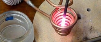
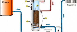
The very principle of operation of an induction heater is not as complicated as it might seem. As an example, we can consider vortex-type heaters. They are widely used in heating boilers, most of the population is familiar with them. From the name it is clear that energy is generated from a magnetic field, which is transferred to the coolant.
The water that enters the device is heated by the supplied energy, after which it enters the heating system. To create pressure, an ordinary pump is used.
Thus, water circulates inside the system, protecting it from overheating. At the same time, the coolant constantly vibrates, which protects against the appearance of scale. In fact, this is the entire working diagram of this unit.
DIY induction water heater: diagram
The device is a transformer with two windings: primary and secondary. The first circuit converts electrical energy into eddy currents, thereby creating a directed induction field, which provides induction heating. In the secondary circuit, the converted energy is transferred to the coolant (in our case, it is water).
It is important to consider the type of material from which the winding is made. Thus, in household models, copper wire is most often used. This material is well suited for heating water in boilers.
In addition to the transformer, the device contains a generator and a pump (optional).
Diagram of a simple induction water heater. As you can see, the device has a fairly simple design and a small number of elements.
Heat generator components and parts
The device includes:
- an alternating current generator that increases the frequency of the current;
- the inductor, which transforms electricity into magnetic energy, is a coil of copper wire;
- heating element, most often its role is played by a metal pipe.
Thanks to this design, energy transfer is carried out practically without losses. Efficiency reaches 98%.
Principle of operation
An induction water heater consists of a generator, a coil and a core, the latter is heated by electromagnetic energy
The device converts electrical energy into electromagnetic energy. The latter, in turn, acts on the core (pipe), which heats up and transfers thermal energy to the water. All these energies are converted by an inductor consisting of a coil and a core. The generator is used to increase the frequency of the current, since with a standard frequency of 50 Hz it is difficult to achieve high heating.
In factory models, the current frequency reaches 1 kHz.
Homemade
Obviously, a homemade simple induction heater will weigh little, but will have relatively good efficiency, with a compact size.
A pipe with a winding will be used as the core. You will also need a second, similar pipe. Its function will be heating.
Features of devices
Using such a device at home allows you to get maximum performance and operational reliability. In this case, the unit does not need to be accompanied by special documentation and permission for installation, for example, as a gas boiler. By using an induction heater as a traditional heating boiler, in some cases the use of a pump will not be required. The movement of the coolant is achieved through convection processes: when heated, water turns into steam.
It is worth noting that an induction water heater has many advantages that set it apart from its competitors.
- The cost of such a device is insignificant.
- It is possible to assemble the heater yourself.
- Doesn't make any extraneous noise. The coil vibrates quite strongly during operation, but it is practically not noticeable.
- Due to constant vibration, dirt and scale do not have time to attach to the functional elements, so the device does not need regular cleaning.
- It contains a heat generator, which is very easily sealed. Water, acting as a coolant, is placed in a heating element, due to which energy is transmitted through a magnetic field. It does not require the use of contacts, and therefore oil seals and various rubber seals, which tend to quickly fail.
- It rarely breaks, since a simple tube is responsible for heating the water, in which there is simply nothing to break or burn out.
By choosing an induction water heater, the owner receives a device with minimal maintenance, since it consists of a small number of components. And they, in turn, very rarely fail.
Operating principle of an induction boiler
But you can’t do without shortcomings. As with any type of technology, they exist.
- High electricity consumption, which will result in high electricity bills;
- The device gets very hot, and everything around it becomes hot, so you should not touch the device while it is operating.
- An induction water heater has strong heat transfer, so it is necessary to install a temperature sensor to prevent overheating of the device, and, accordingly, an explosion.
Components
For the device you will need:
1. Plastic pipe; 2. Stainless steel mesh; 3. Steel wire; 4. Copper wire; 5. Welding inverter.
The circuit of an induction heater created by yourself will be very simple, hence the light weight and compactness of the device.
The basis is a coil that will play the role of an inductor. It is located in a plastic case. Inside the coil itself you need to place a piece of steel pipe, on which you need to make 2 pipes (inlet and outlet). They will be needed to circulate water in the heating system. The coil, in turn, must be connected to electricity for the device to function.
Note!
- Do-it-yourself Gauss cannon: TOP-130 photos of the best ways to create it yourself. Design features + master class for beginners
- DIY clamps - a step-by-step master class for beginners. Schemes for manufacturing different designs + 170 photos
Do-it-yourself electric scooter - a master class with step-by-step instructions for doing it yourself. Tips and simple patterns for beginners + the best photo reviews
If there is an inverter, you can use a slightly different connection method. In addition, this will increase the frequency of the current, and as a result, the efficiency of the device.
The converter itself, due to which another type of connection is possible, consists of 3 components:
1. Transistor control circuit; 2. Rectifier; 3. Two-transistor inverter.
A distinctive feature of this method is the secondary winding of the wire. It is short-circuited and is located in the first winding. In fact, the operating principle can be compared to a transformer, but the desired outcome is completely different.
In a transformer, they try to avoid heating, while in an induction heater, it’s the opposite. You can download the diagram for free.
You can get such an inverter from a welding machine, but the connection diagram will be somewhat more complicated. Thus, you can assemble induction heating with your own hands from a welding machine.
Note!
- DIY rocking chair: TOP-120 photos of the best manufacturing options. Master class on creating a rocking chair at home
Smokehouse from a gas cylinder - the best master class on making a homemade smokehouse with step-by-step photo diagrams for beginners
Do-it-yourself compressor: TOP-130 photo reviews of finished compressors. Step-by-step instructions + diagrams and drawings
What is an induction water heater and how does it work?
The operating principle of all induction-type devices is based on the ability of eddy (induced) currents to heat objects located in the radiation field. An induction instantaneous water heater still belongs to the category of equipment that is constantly being improved, but existing models also have a fairly high thermal power.
Structurally, a water heater of this type is a closed metal container of small diameter. The main element is a high-frequency induction coil placed inside the tank. The characteristics of the wound spiral depend on the required power and performance of the device. Inside the coil there is a small diameter pipeline through which heated water passes.
The main electrical element is a step-down transformer and an inverter, which makes it possible to obtain high-frequency currents from ordinary household electricity. When such a current passes through the induction coil, the space inside it is heated, which can be filled with special antifreeze or even ordinary water.
Due to the increase in temperature inside the coil, the water passing through the copper tube is heated. Copper is used due to its good thermal conductivity.
Operating principle of an induction water heater
As you can see, the circuit of an induction water heater is quite simple. Having the skills to work with electrical equipment, you can even assemble such a device yourself.
Experts note a number of positive aspects of using induction technology to provide hot water supply and even heating:
- Induction-type units are characterized by exceptional durability. The average service life reaches 25-30 years. This does not require expensive maintenance; preventative cleaning can be carried out once every 10 years.
- Induction water heaters can have significant thermal power, along with this, electricity consumption (compared to traditional equipment using heating elements) is reduced by 30-50%.
- The formation of scale on an induction heating element is impossible in principle. An alternating magnetic field prevents the formation and deposition of sparingly soluble salts on the internal surfaces of the structure.
Of course, water heaters of this type cannot be classified as cheap household appliances; today, even modifications of small power cost at least 30 thousand rubles. But constant improvements in design and increased sales volumes lead to a gradual reduction in prices for such devices. Therefore, in the near future, induction water heaters may become available to the general public.
Application
Today, the scope of application of heaters of this type is very large. It is also necessary to take into account the fact that there are a large number of modifications and possibilities for upgrading heaters.
Industrial sector
It is used for melting metals, producing certain types of alloys, which are then used in a wide range of works. By creating alloys, metal wire is produced.
Various modifications of the induction heater are used for car service, for the purpose of heat treatment of spare automotive parts. In fact, the technology is used for the same purpose in medicine; medical devices, furniture and equipment are subjected to heat treatment.
Pros of technology
It is used in a wide range of industries due to its low cost (depending on the type and modification) and high efficiency. Mainly used in the alloy manufacturing industry, where ultra-pure alloys can be produced through the use of an induction heater.
Note!
Do-it-yourself wind generator: TOP-170 photo reviews of finished devices. Detailed DIY instructions for beginners
Do-it-yourself spot welding - the best master class on making homemade spot welding with step-by-step photo diagrams of do-it-yourself work
Do-it-yourself tennis table: TOP-150 photos of the best manufacturing ideas. Master class on creating a tennis table at home
An environmentally friendly technology that does not pollute the environment in any way, and at the same time is cheap to produce.
It is actually possible in any shape, which allows you to evenly distribute heat over the entire area, eliminating local overheating.
In fact, if you compare this technology with similar ones, it has no disadvantages. Except for one thing: it involves the need to connect the inductor and the workpiece. If this is not done, the heating will be insufficient in most cases.
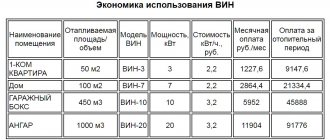
What is an induction water heater
INDUCTION BOILER, INDUCTION HEATER, INDUCTION HEATER
It took almost a year to produce the results of this article, and a lot of money was spent, so please, before drawing conclusions, read from the first lines to the end - many things will become clear.
It all started when the topic of replacing the heating at home came up. Gas is good, of course, but our boiler is quite old and we don’t want to change it - it has a smooth temperature control, while modern ones are discrete, i.e. they do not burn at half or 1/4 a quarter of the maximum, and the smoother the adjustment, the more economical any heater is. Yes, the savings are not big, but I can spend even 200-300 rubles in savings at my own discretion, rather than paying for gas.
Well, as expected, it all started with a search engine. I typed in the search query “Induction boiler” and began to study the pages found. And I had to think seriously.
On one of the pages promoting induction boilers, outright paranoia was stated, I can’t resist quoting:
The heating element heats up because current flows through its conductor with increased resistance, so in any case it heats up to the specified 600 - 750 * C and the coolant on its surface always boils. Because of this, the heating element quickly becomes overgrown with scale. As a result, heat transfer decreases, and the heating element eventually burns out.
In an induction boiler, you can use different coolants, even petroleum products, if they are not overheated above 70* C.
WHAT. 600-750 degrees?!
Okay, let's take an oil heater, throw out the thermostat and heat it up to maximum, praying beforehand that it won't burst. Of course, it is better to see once than to hear a hundred times. SO LET'S LOOK
So, the temperature of the coil is 421 degrees at a radiator temperature of 168 degrees, and this takes into account the fact that there is oil inside, and its thermal conductivity is 5 times worse than water. Where does the toga come from, interestingly, 600-750 degrees? So, just in case, the melting temperature of aluminum is 660 degrees, copper 1100. However, I know where - some nichrome alloys have a maximum operating temperature of 750 ° C, but there are great doubts whether it will be achieved.
Is the heating element overgrown with scale? And did they also tamper with the photo?
Hmmm.
Oho-hoyushki ho-ho. For those who don’t know, this is a heating element from a washing machine, and at one time I changed them quite often, because I worked in a repair shop. So, this terrible word SCALE:
Scale is hard calcium deposits that are difficult to dissolve and are formed as a result of the formation of steam or heating of water. In addition to limescale, when water is heated, carbon dioxide is also formed. But its quantity matters only on an industrial scale when working with hard water. So in boiler rooms, when descaling boilers, it is necessary to ventilate the premises, but when boiling water, it is also necessary to ensure good ventilation in the room.
Scale formation during heating of water always occurs if the water is hard. Only the scale may be different, because... Water hardness may not necessarily be carbonate. It is clear that the cause of the formation of carbonate scale is calcium and magnesium salts. If scale formation occurs due to calcium silicate, then the scale turns out to be sulfate. Silicic acid compounds of substances such as iron, aluminum or calcium lead to the formation of silicate scale. So, the formation of scale after working with hard water does not mean that it is carbonate scale that has fallen out. Although it should be clarified that carbonate scale is the most common.
Ha! From this it is not difficult to conclude that scale is supplied only with a new portion of water, and the water in the system is changed extremely rarely and this very layer of scale is formed only once and gradually thickens with each new portion of water, and water is not added to the system often either. Consequently, the heating element of the boiler will reach the state shown in the photo in about 20 years after the aluminum radiators rot, since scale settles not only on the body of the heating element, but also on the body of the boiler itself, less, but still settles.
And by the way, it is quite possible to get rid of scale in heating - 100 grams of anti-scale in the system will completely eliminate this problem - tested by operating an electric boiler for three heating seasons.
But let’s return to the advertising of induction boilers:
In heating element boilers, only water can be used as a coolant and, moreover, distilled water is best.
In maintenance, heating element boilers are less practical than induction boilers, because the transition contact between the power supply conductor and the conductor of the heating element itself is constantly overheated, and as a result is oxidized and weakened. It is necessary to constantly ensure that the power supply conductor does not burn out; otherwise, if it burns out, the threaded connection of the heating element may be damaged and such a working heating element will have to be replaced. This problem does not exist in induction boilers, because the connection of its heating element with the power supply is carried out through the electromagnetic field of alternating current.
Well, yes, of course, of course. Is the inductor coil connected to the socket wirelessly? COOL! Most often, burnout occurs at connection points under heavy loads and continuous round-the-clock operation, so overheated contacts do not sound convincing. Okay, what's next?
Induction boilers can be installed in any place, even not in a separate place. They are fireproof and operate silently.
Yeah. Is the heating element inside the boiler constantly hitting the walls with its head and making it impossible to stay in the room at all?
Induction boilers provide human electrical safety much higher than heating element boilers, because the heating element itself can burn out in two ways: a) with depressurization of the housing; in this case, heated nichrome crumbles when water hits it - there is no danger of a person coming under voltage; b) without depressurization of the housing; in this case, heated nichrome may stick to the body of the heating element. The heating element continues to work, and through the water the metal body of the boiler becomes energized.
It is a logical argument that if the boiler is installed in violation of safety rules, any power device must be grounded. But he can kill a fool with a battery, well, if it’s with a slingshot and to the head.
It is not yet possible to make the induction coil of an induction boiler with powers of 3 kW or more at 50 Hz small and compact. Therefore, the heating element boiler has much smaller dimensions at the same power than an induction boiler.
It will never be possible - the frequency is low, only 50 Hz, and you need a certain inductance, and even a wire, so that it does not heat up when these same 3 kW pass through it. So an induction boiler will always be large.
Well, the schematic diagrams of induction boilers are actually something. One of the sites suggested using this circuit for an induction boiler:
Actually, I smiled for quite a long time - with a power supply of 10.30 volts, are they going to heat up the boiler? Yes, the power supply for this fart will generate more heat than this toy for middle school children.
Frankly, I came across one rather interesting version of a thyristor circuit, but operation at audio frequencies did not attract my attention.
One of the advertising slogans literally made me laugh:
Saving on electricity consumption
Consumption of 2.5 kW instead of 4–5 is an excellent result. But it turned out to be not enough for ambitious and thrifty home craftsmen. But where can I get cheap electricity for the stove? It turns out that the answer has been known for a long time.
This device is called an inverter, and it converts direct current into alternating current. With its help, you can reduce current consumption for heating to almost zero.
To reduce energy consumption we need the following:
Two batteries with a capacity of at least 190 Ah (preferably 250 Ah). 4 kW inverter.
Battery charger (24 V).
The main pipes must be made of non-magnetic material (plastic, aluminum, copper).
We connect the batteries in parallel and put them on constant “charging”. The process that occurs in an electrical circuit:
The batteries generate direct current, which is supplied to the inverter.
The inverter converts direct current into alternating current 220 V.
Current from the inverter is supplied to the induction furnace, which operates in normal mode (flow).
The charger continuously recharges the batteries.
Honestly, this is a quote from the Internet and I can’t even imagine who it’s aimed at.
I didn’t have the determination to make an induction boiler right away, so I decided to try first assembling an induction heating radiator. The first thing that was asked for was an induction stove, but there was no agreement with the toad on the topic of purchasing it, so having found a diagram of an induction stove on the Internet, the power part was isolated from it, which was assembled.
I immediately ordered IRFPS37N50 from the same seller, as if I sensed something bad. And delivery in this option was relatively inexpensive - two orders, and one delivery fee.
In general, having played enough with single-ended devices, I came to the conclusion that the thing is good, but the slightest error during adjustment kills the power transistors. Therefore, I decided to take a different route - try to assemble a push-pull circuit for an induction heater, since powerful field workers were already on hand. After a little thought, I decided to use the IR2153 half-bridge driver, and so that it would not be killed by heavy gates, I powered it with 1.5 A emitter followers. The result was the following circuit:
The idea was quite simple - film capacitors do not hold high currents very well, so use several of them, and if there are several of them, then it will be possible to select the capacitance in such a way that the resulting LC circuit will be driven into resonance and obtain maximum magnetic fields.
It was decided to use a square pipe as a heat exchanger - a heat exchange area both outside and inside, and this naturally only works to its advantage.
There were suspicions that the electronics would get very hot, since the single-cycle version had to use radiator airflow. Well, so that the air flow would not be wasted in vain, it was decided to use it as a convection flow - through a pipe to direct it inside the square pipe of the heat exchanger, thereby increasing the performance of the structure.
You can also secure the coils with sealant; in principle, the main thing is that they hold fairly tightly even if the heater falls. Although, of course, if such a thing would be dropped, if only during transportation - it turned out to be a heavy toy, but you couldn’t carry it on yourself, so there was no thought at all about the weight. High-temperature cambrics were put on the ends of the coils - not heat shrink, but fiberglass, it is much more expensive than heat shrink and looks like material.
A drawing was made, printed on paper, taped to a sheet of chipboard, holes were drilled in the corners into which nails were inserted. The studs were pre-loaded with pieces of heat-shrink tubing and the coils were wound on this template. After winding, the coils were dipped in epoxy glue and heated with a hairdryer to better impregnate the stranded wire bundles with which the coils were wound. A wire with a diameter of 0.35 mm was used; there were 28 cores in the bundle. Later I made more coils and washed them with sealant - they turned out too runny, although they held up pretty well.
Then all this was collected into one device and adjusted. As it turned out, unlike the single-cycle version, the power transistors with the same radiator did not need airflow, but the fan was still left in - heat exchange is much better with it. However, the speed was reduced to a minimum of audibility - so it will have more resources, it will drive less dust inside, and the buzzing will not irritate.
After assembly, naturally, it was necessary to compare which is actually more profitable - the oil pan or the induction cooker. A whole bunch of measurements were carried out, but each time the inductor turned out to be the winner in relation to the carnival, which quite infuriated the viewers from YouTube. Yes, of course, some measurements were not entirely correct, but the last episode practically did not provoke criticism, although opinions that I did not go to school and do not know the conservation law still flashed. Yes, I actually did not encroach on this law - we are talking about productivity and nothing more.
In general, the latest measurements have been compiled into a table, based on the results of which you can draw your own conclusions about what is more profitable.
Immediately questions began to appear like “Could you assemble a control board for me?” Yes, of course I could, but there are just two new things:
This is expensive because you have to make boards manually, COMPLETELY manually, since I don’t see a queue for this device and I don’t need to order boards from the factory with a minimum batch of 10 pieces. And making a board involves ironing, hand drilling, and tinning, i.e. quite a lot of time that I can’t just take and give away - you know, life is limited and spending it on something that is not interesting to me and without taking money for it is simply stupid.
The likelihood of an untrained solderer completing this design is not very high, since in addition to the board, an inductor is also required, and these are coils, the number of turns in which directly depends on the method of their connection, the thickness of the steel and the distance between the coil and the steel.
The result of the competition between the induction boiler and the oil boiler was, of course, impressive and the idea of assembling an induction boiler stuck VERY tightly in my head. The first thing that needed to be decided was which inductor to assemble. Of course, unlike domestic induction boilers, I was not going to make it at 50 Hz. And for this, more serious capacitors were already needed - there are too many photos of exploding film capacitors on the Internet. That is why capacitors were ordered for induction cookers - they will definitely withstand both current and voltage. To suppress impulse noise in the power supply, capacitors were ordered and MKP series capacitors, which are used in induction cookers, were purchased to create resonance. For power supply I took 5 µF and 3 µF, for the inductor 0.27 µF. Where I bought there was already a sign that the product was not available, so choose MKP CAPACITORS yourself.
Another factor for the creation of an induction boiler was their mass production, although not ours, but a more compact and high-frequency one - Chinese induction boilers with a power of 6 kW and 10 kW. True, it was clear from the photos that the Chinese were limited to a maximum power of 3 kW from one heater section, since they used single-cycle converters - this can be seen from the presence of two and three identical control boards with forced ventilation. Using a push-pull bridge inverter, I expected to get 4-5 kW from one section, and given that the power section can serve 2 sections of the inductor, there were no problems with power at all.
Why is the power of an induction boiler limited? Everything is quite banal - to obtain resonance, a certain inductance is required. If the resonance is at audio frequencies, then both the control and the inductor itself will become audible, and this will be VERY tiring, to put it mildly. If we go to higher frequencies, then we will be forced to reduce the number of turns, and the strength of the magnetic field necessary for the occurrence of Foucault currents, i.e. eddy currents, which heat the steel, will decrease. After all, the strength of the magnetic field is directly proportional to the number of turns and the current flowing through them. Winding a step-up transformer to obtain higher voltage did not work for two reasons:
Dimensions and cost of ferrite
The problem of inductor insulation and power control part
Yes, yes, insulation is also important here - with resonance and a bridge inverter, it applies about 800 volts to the inductor coil. If you double the frequency, you will also have to reduce the number of turns by 2 times, and to obtain the same power you will have to double the applied voltage, and this is already 1600 volts. No, I didn’t dare to try this, and I don’t advise you either - this thing is becoming too dangerous.
The first version of the control scheme made it clear that in addition to increased accuracy, the scheme needed to be slightly changed, which was done. However, I managed to check something in the first version:
Not impressed at all. However, after thinking a little, I came to the conclusion that I was in a hurry with the check - the magnetic field around the inductor coil was not closed, and this led to losses - the steel sheet that was located next to the boiler became noticeably heated during the experiment.
Well, since I still lost control of the induction boiler, it was decided to assemble an indestructible stand for testing inductors, and, in fact, a new, more thoughtful control for the induction boiler.
After sitting for an evening, I ended up with this diagram of the testing stand. In principle, the only non-traditional thing here is the first stage of current limitation - the effective value is formed not by the duration of the pulses, as is usually customary in the TL494 controller, but by changing the conversion frequency. This solution is primarily due to the fact that there is no need to deal with self-induction pulses, which cause heating of power transistors, and since the load has a reactance that increases with the frequency used, there was no doubt about the operability of this circuit solution. In addition, an analog frequency meter was introduced into the circuit, allowing you to navigate the frequencies used. Of course, the frequency meter scale was calibrated according to the readings of a real frequency meter.
The boiler control also underwent some changes and the final circuit diagram took on the following form:
The circuits have a general principle for controlling the current flowing through the load - frequency regulation. In the stand, the frequency depends on the current flowing through the load, but for the boiler this dependence is formed by the thermostat. Moreover, the adjustment has two stages - the first reduction in consumption occurs when the coolant temperature reaches a certain value and is carried out in steps. The second stage of regulation is smooth and changes the power supplied to the boiler inductor depending on the temperature of the heated room. Thus, the inertia of the heater is completely absent.
After an unsuccessful test of the first version of the induction boiler, shielding of the coils with ferrite rods was tested - the performance increase was pronounced. This, of course, inspired me, but not much - the project was becoming too expensive - a lot of ferrite was required, but it is not cheap.
The solution to the problem came in two stages. At first it was decided to use a toroidal heat exchanger with a labyrinth inside, but after a little reflection, a sketch of a toroidal induction boiler without a labyrinth and with a different arrangement of inlet and outlet pipes appeared.
The first turn-on showed that there were too few turns on the boiler and the coil had to be sealed and re-wound.
There was essentially a week left before assembling the control board for the induction boiler, but my hands were itching - the boiler was already ready and the readiness of the test bench also gave me no rest.
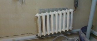
A heating model with several options for electric boilers was assembled and tested, but the final experiment was disrupted - the diameter of the pipes turned out to be too small and the water in the boiler with heating element simply boiled:
The heating model was redone - a circulation pump was added, which will prevent water from boiling, and the volume of water in the model increased from one and a half buckets to six and a half, which made it possible to significantly increase the duration of the experiment. So, the hour of X, or the moment of truth has come:
To be honest, I was upset. There was no magical performance increase. It is clear that with self-circulation the probability of an increase would most likely be - with the slow movement of water, bubbles form on the surface of the heating element, which are carried away into the expansion tank, carrying away heat, but when using a circulation pump this effect is negated - the heating element is washed too intensively with water and gas formation is reduced tenfold.
Of course, the induction boiler was driven into resonance, but the dependence of the flowing current is linear - it begins to increase as the frequency increases and approaches resonance, and after passing it, the current also decreases linearly. No surges of current flowing through the coil were detected.
Well, since the model is fully assembled, I couldn’t resist trying to play around with the electrode boiler:
For these experiments, a new, modern electric meter was also purchased, which, after completing the measurements, simply turned out to be unnecessary. Of course, my curious nose was stuck into it too:
In general, I did not completely assemble the boiler control board - there is no difference in the heat output of an induction boiler and a boiler using heating elements, therefore I will not need this board. No, I won’t disassemble it completely yet - I have both TL494 and IR2110 in stock, but I haven’t soldered the power transistors to it yet. Let him lie around for now. But I will take into account the ideas of induction heating - with such a set of power devices you can slowly or quickly heat a lot of steel objects for various purposes. So experience was gained and the stand remained for further experiments.
Of course, it’s a pity that the idea with an induction boiler turned out to be untenable, but there is a technology for manufacturing induction heaters, which are electronically more complex than factory convection heaters, but use more accurate temperature control, or the use of continuous regulation, as in a boiler you can achieve decent savings.
Let me remind you once again - we are not talking about efficiency, but about productivity, and there is no need to wave textbooks on physics and thermodynamics in my face - the experiments described in the textbooks were carried out in ideal conditions, and a home will never be in such conditions, it always has heat exchange with the environment. I wasn’t smart enough to calculate mathematically what and how would happen, so I put together several models and checked everything EXPERIMENTALLY and saw everything with my own eyes. So stop your sarcasm and if you have doubts, you can repeat everything - all the circuit diagrams, all the designs used are described in sufficient detail.
Induction boiler, induction heater, DIY induction heater
Description of the design of an induction boiler, induction heater with full descriptions and circuit diagrams
Source: soundbarrel.ru
How to make it yourself
Let's consider the second method of making a powerful induction heater with your own hands. Unlike the first method, there will be much fewer components, but its power will be higher due to the use of slightly different components and connection type.
We will need:
1. Welding inverter; 2. Generating welding current (from 15 A); 3. Copper wire.
It is recommended to use polymer materials as the core. This is due to the fact that they are able to withstand fairly high temperatures when heated. In our case there will be a polymer pipe with a diameter of 50 mm.
It is necessary to wind the wire around the core and connect it to the inverter terminals so that there is no twisting.
Homemade device options
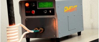
The Internet contains a sufficient number of different designs created for various purposes. Take a small-sized induction heater made from a 250-500 W computer power supply. The model shown in the photo will be useful to a master in a garage or car service for melting rods made of aluminum, copper and brass.
But the design is not suitable for heating premises due to its low power. There are two real options on the Internet, whose tests and work are filmed:
- water heater made of polypropylene pipe powered by a welding inverter or induction kitchen panel;
- steel boiler heated by the same hob.
Reference. There are other, completely home-made designs, where frequency converters are assembled by craftsmen from scratch. But this requires knowledge and skills in the field of radio engineering, so we will not consider them, but will simply give an example of such a circuit.
Now let's take a closer look at how to make induction heaters with your own hands, and most importantly, how they then function.
We make a heating element from a pipe
If you have been actively searching for information on this topic, you have probably come across this design, since the master posted its assembly on the popular YouTube video resource. After which many sites posted text versions of making this inductor in the form of step-by-step instructions. Briefly, the heater is made like this:
- Inside a polypropylene pipe with a diameter of 40 mm and a length of 50 cm, metal dishwashing brushes are pushed (chopped wire - wire rod can be used). They must be attracted by a magnet.
- Threaded bends are soldered to the pipe for connection to the heating network.
- On the outside, 4-5 PCB rods are glued along the body. A wire with a cross section of 1.7–2 mm² with glass insulation, used in welding transformers, is wound on them.
- The hob is disassembled and the “native” flat-shaped inductor is dismantled. Instead, a homemade pipe heater is connected.
An important nuance. The length and cross-section of the wire for winding the coil should be determined from the standard inductor of the stove so that it matches the power of the field-effect transistors in the electrical circuit. If you take more wire, the heating power will drop; if you use less, the transistors will overheat and fail. How it looks visually, look at the video:
As you might guess, the role of the heating element here is played by metal brushes located in the alternating magnetic field of the coil. If you run the hob at maximum, while simultaneously passing running water through an improvised boiler, you can heat it up by 15-20 °C, as tests of the unit have shown.
Since the power of most induction cookers is in the range of 2-2.5 kW, using a heat generator you can heat rooms with a total area of no more than 25 m². There is a way to increase the heating by connecting an inductor to a welding machine, but this has its own difficulties:
- The inverter produces direct current, but alternating current is needed. To connect an induction heater, you will have to disassemble the device and find the points on the diagram where the voltage has not yet been rectified.
- You need to take a wire of a larger cross-section and select the number of turns by calculation. As an option, copper wire Ø1.5 mm in enamel insulation.
- It will be necessary to organize cooling of the element.
The author demonstrates checking the performance of an inductive water heater in his video presented below. Tests have shown that the unit requires improvement, but the final result, unfortunately, is unknown. It looks like the craftsman left the project unfinished.
How to assemble an induction boiler
In this case, there is no need to disassemble the cheap Chinese stove. The point is to weld a boiler tank according to its dimensions, following step-by-step instructions:
- Take a steel profile pipe 20 x 40 mm with a wall thickness of 2 mm and cut blanks from it to the width of the panel.
- Weld the tubes together lengthwise, joining the smaller sides.
- Weld iron caps hermetically at the top and bottom to the ends. Make holes in them and install threaded pipes.
- Attach 2 corners to one side by welding so that they form a shelf for the induction stove.
- Paint the unit with heat-resistant spray enamel. The assembly process is shown in more detail in the video.
Final assembly and commissioning consists of mounting the boiler on the wall and inserting it into the heating system. The hob is inserted into the socket from the corners on the rear wall of the tank and connected to the mains. All that remains is to fill the system with coolant, bleed the air and turn on the inductor heating.
Here you are faced with the same problem that occurred with the previous model. Undoubtedly, induction heating will work, but its power of 2.5 kW is enough to heat a couple of small rooms when it’s freezing outside. In autumn and spring, when the temperature has not dropped below zero, a homemade boiler can heat an area of 35-40 m². How to properly connect it to the system, see the next video:
First
The wire must be cut into pieces approximately 5 cm long. Fill the core with these pieces, which is then sealed with wire mesh. Install the adapter from the pipe where the heater will be connected to the heating. Next, you need to wind a wire around the heater, the length of which should be about 16 m.
After this, the core is connected to the heating, the heater itself is connected to the inverter. Please note that before testing, you need to make sure that there is water inside the device. If you turn it on without water, it will overheat very quickly and melt.
Second
Regarding the first option, this one is much simpler, but requires additional costs. A long pipe is used as a base. Approximately a meter of paint must be removed from its surface. When the paint is removed, the cleaned area should be covered with electrical fabric in 3-4 layers. Next, copper wire is wound on top of the fabric, forming a coil.
The assembled device is isolated, all that remains is to connect it to the inverter.
Mandatory safety precautions
Any work performed with electricity, especially if the work in one way or another involves the participation/use of water in the process, requires full compliance with safety requirements.
Safety precautions must always be observed, with special care in cases where the device is assembled independently, using independently acquired skills and knowledge.
In addition, before starting any work, it is initially necessary to thoroughly study the theoretical part. This will allow you to understand the upcoming work in more detail and eliminate possible errors and misunderstandings.
In this article, we looked at several ways to make a heating device with your own hands. Photos of the induction heater, instructions and recommendations for use can be found on the Internet.
Please note that in the case of homemade induction heaters, they cannot be installed in residential areas. This is caused by electromagnetic radiation that comes from both inside and outside the coil. In fact, it will heat not only the core, but also metal objects and devices that are exposed to the magnetic field.
It is recommended to use only with a galvanized screen to eliminate this possibility.
DIY induction heating. Technique for extracting energy from a current transformer
DIY induction heating. Technique for extracting energy from a current transformer
The goal is the practical implementation of heating a house using the technique of induction melting of metals. The idea is not new and is to place the inductor around the heating pipe. By heating the pipe, we thereby heat the water that circulates in the heating system. The basic prerequisite that can significantly reduce energy costs is an oscillatory circuit (inductor->capacitors) that operates in resonance. The voltage increases by about tens of times, which heats the metal.
Classical induction circuits, as the practice of replacing failing transistors has shown, requires expensive components. The basis was taken as an induction heating circuit using the ZVS (zero voltage switching) method of switching transistors. The diagram is taken from the site https://www.rmcybernetics.com/projects/DIY_Devices/diy-induction-heater.htm.
In the assembled circuit, STP40N10 transistors and 50SQ100 5A, 100V Schottky diodes were used; resistors are 240 ohms, the measured capacity of the capacitor bank CBB81/224/2000V is 2.3 uF. The magnetic permeability of the ferrite ring is L2, according to the seller 10000, but the circuit starts with a ferrite ring. Power supply - two batteries are replaced with an OSM1-1.6 transformer with an alternating voltage of 24 volts and a constant voltage of about 27 volts on the capacitor. The scheme worked immediately, no settings were required. A more or less interesting result for a given inductor size starts at 20 volts.
The voltage on each of the transistors relative to the housing is 800 Volts, no matter where you measure it. The operating frequency of the circuit without a metal pipe in the inductor is 321 KHz, current consumption is 1.7 Amperes. When adding a metal pipe, the frequency drops to 138 KHz, the current consumption increases to 5A. A 0.5-inch pipe, with an inductor with an internal diameter of 85 mm, is heated in the area of the midpoint to a cherry color.
It is best to use film capacitors from Evox Rifa, Faratronic, and Pilcor in such circuits. The efficiency will increase, and the number of air conditioners will be required several times less. The current consumption is determined by filling the inductor with metal. Should be used for seamless pipes with maximum wall thickness. With a current consumption of more than 12 amperes, STP40N10 transistors do not last long. The water cooling recommended on the website is not used. The radiator and inductor are heating up, the capacitors are cold. To cool the transistor radiators, I used a computer fan. If necessary, heat removal can be organized on the same heating riser.
Current transformer. The second, no less, if not more interesting way of heating the coolant is a current transformer. The current transformer is a ferrite ring mounted on a wire running from the capacitor block to the inductor. Ferrite rings of any magnetic permeability are suitable. Including a ring made of transformer iron. The lower the magnetic permeability of the magnetic core, the smaller the radius of the ring is permissible, the lower the frequency of the output current, the more the magnetic core heats up. In the case of using transformer iron, heating efficiency is maximum. Ferrite rings with an internal diameter of less than 60 mm should not be used for long-term operation of the circuit. When the internal diameter of the ferrite ring is small, less than 50 mm, the current consumption required to maintain resonance sharply increases, and the transistors fail. In the case of using a core from a fuel assembly, a gap is required, this is not according to Feng Shui. In the case of counter-winding windings, as shown in the photograph, there is no emf.
Below is a load connection diagram. You can turn on a 220V 95W lamp without a diode bridge, but you should reduce the number of turns of the current transformer to about five, otherwise the lamp will burn out. You should not pay attention to the double pair of turns used in winding. The same should be done with a pair of wires, black and red; on transistor radiators, high-voltage capacitors from microwave ovens were connected to them. The capacitors got very hot, I had to replace them, let the wires remain for now.
Ferrite rings placed in the inductor increase the frequency to 400 kHz, the current transformer lowers it to 100 kHz. The brightness of the lamp is adjusted by frequency by increasing or decreasing the core of ferrite rings in the inductor.
The tester shows that when the load was connected, the current increased by two amperes. (In the first case, the current must be multiplied by 100) This is approximately equal to the power of the lamp used. There is no free energy withdrawal from a current transformer. Connecting an active load increases the current consumed by the device. But using ferrite rings to heat the coolant in addition to the inductor is a very interesting option.
Arc discharge. For every three or four turns of a current transformer there are 1000 volts. An attempt to measure voltage on a larger number of turns ended in failure due to failure of the tester. It can be assumed that the voltage at the current transformer is about five to six thousand volts, so the third heat source in the proposed circuit is an arc discharge. I have not yet decided how to use it to heat the coolant. Anything with which the arc discharge is in close contact melts.
Subtotal. 1. Heat the heating pipe using Foucault currents. 2. Additional thermal power due to cooling of radiators on which transistors are installed. 3. Cooling the ferrite of the current transformer with coolant (water). 4. Using an arc discharge is problematic. Very high temperature. But very promising. The presence of an arc does not increase the current consumption of the device.
Example man pages:
Download the full manual:
A. Mishchuk - Induction heating. Technique for extracting energy from a current transformer.pdf
31.01.2014
See also:
- Transformer P-600 based on traveling wave effect
- Free Energy device again! DIY Kuldoshin transformer (video victordok)
- Do-it-yourself Tesla transformer on Brovin's car and energy consumption. Radiant energy. Wireless power transmission
- A little about transformers
- Simple DIY induction heater
Rate a homemade product, a master class, an idea. Comments