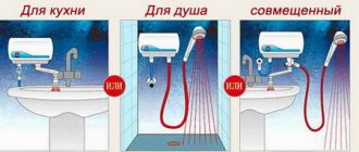
Open circuit with gravity circulation
This option is easy to perform even for a beginner. Here water circulates in the system due to the difference in density of cold and hot liquid. According to the laws of physics, hot water begins to flow upward (since its density is less), and then it cools down and returns to its starting point.
Despite the fact that this type of strapping is quite simple, it requires compliance with a number of requirements. Firstly, in order for water to circulate freely in the system, you need to install the heating equipment half a meter lower than the radiators are located in the house. Secondly, in order to minimize the manifestation of hydraulic resistance, pipes with a cross-section of up to 5 cm are needed, while distribution pipes on batteries can have a value of 2.5 cm. Thirdly, locking devices and fittings directly affect the free circulation of water in the system, therefore, there should be a minimum of such elements.
But for the sake of fairness, it is worth saying that an open system with natural circulation also has a number of its advantages. In addition to the fact that it is the easiest to set up, the financial costs for it are not so great. True, the owner will not be able to constantly control the temperature of the coolant at the outlet, which is why the heating of the circuit is somewhat reduced. Also, the expansion tank occasionally remains open, which means that oxygen has contact with the coolant, which gradually increases the risk of corrosion.
To summarize, it is worth saying that experts recommend this type of heating scheme only for those private houses where people live from time to time, and not on an ongoing basis, for example, for a summer house.
Brands of solid fuel boilers made in Russia
Analysis of technical characteristics will help to get a general idea of long-burning solid fuel boilers. Consumer reviews on independent forums provide an objective assessment of domestic developments.
Table 1. Solid fuel boilers Zota Mix and Pellet produced by the heating equipment and automation plant (Krasnoyarsk):
Table 1. Solid fuel boilers Zota Mix and Pellet produced by the heating equipment and automation plant (Krasnoyarsk)
- The efficiency of boilers of the Zota Mix model range is 80%, Pellet – 90%;
- Zota Mix combined steel solid fuel boilers operate on any type of fuel (liquefied or natural gas, electricity, liquid fuel);
- the combustion chamber and ash box are located inside the water jacket;
- an adjustable chimney damper, a mechanical draft regulator and air suction by an ejector installed in the combustion door ensure complete combustion of fuel with minimal draft;
- the outer surface of the body is coated with an anti-corrosion polymer composition;
- a removable door behind the front panel provides access for cleaning the flue;
- possibility of repair.
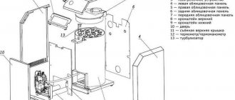
Zota Mix boiler design
- you need a supply of fuel and a place to store it;
- costs for delivery, unloading and storage of firewood, coal, briquettes;
- reduction in the productivity of Zota Mix boilers when using low-quality fuel (brown coal by 10÷20%, raw firewood by 60÷70%);
- for Zota Mix - manual loading of fuel, cleaning of the ash pan, firebox walls, flue ducts and smoke pipe;
- mandatory preparation of boiler water (hardness up to 2 mEq/l);
- installation in a separate room;
- For boilers of the Zota Mix line, it is necessary to install a heat accumulator, a smoke exhauster, and a boiler.
Table 2. Combined solid fuel devices with a water circuit (AKTV). (Novosibirsk city):
Table 2. Combined solid fuel devices with a water circuit (AKTV). (Novosibirsk city)
- budget option for solid fuel boilers with a water circuit for the home (price 11,000÷25,000 rubles);
- compact size;
- the water heat exchanger covers the firebox from all sides (except the front);
- retractable ash drawer;
- mounting socket for draft regulator;
- the ability to connect to a chimney of any configuration;
- the steel heat exchanger allows for simplified connection to the heating system (without mixing);
- The design is adapted to operate on gas and electricity.
Boilers "Karakan" from
- outdated design, primitive automation of low quality;
- The technical characteristics declared by the manufacturer (power, heated area and efficiency) according to consumer reviews do not correspond to actual indicators.
Table 3. Solid fuel pyrolysis boilers Bourgeois & K from NPO TES LLC (Kostroma):
Table 3. Solid fuel pyrolysis boilers Bourgeois & K from NPO TES LLC (Kostroma)
- ensures stable combustion of fuel of any grade and degree of humidity;
- efficient operation of the boiler from one fill for 8 hours;
- economical fuel consumption;
- compatibility of the generator with natural or forced circulation systems;
- an environmentally friendly unit, the fuel undergoes a complete combustion cycle without producing harmful emissions into the atmosphere;
- The design of the firebox ensures reaching an effective operating mode in 40 minutes.
Solid fuel pyrolysis boilers "Bourgeois & K"
- complex installation: the connection must be made by employees of specialized enterprises that have a license for this type of activity (otherwise the manufacturer’s warranty does not apply to the unit);
- manual fuel filling and combustion chamber cleaning;
- heavy weight.
Installation and operation of solid fuel boilers must be carried out in accordance with fire safety rules
For heating a country house. In a garage or greenhouse, it is possible to make long-burning solid fuel boilers with your own hands. Videos with materials on this topic can be found on the Internet. But remember that the main condition for using heating equipment is fire safety. And only a certified manufacturer can guarantee the fulfillment of this condition under proper operating and installation conditions of the equipment.
https://youtube.com/watch?v=3sfw2qpCMrY
https://youtube.com/watch?v=1z6OOs3WdH4
CLASSIFICATION OF FIRES AND GENERAL CHARACTERISTICS OF PROCESSES
Fuel combustion in boilers and various technological devices is carried out in combustion devices (furnaces). When using physical and chemical heat from the exhaust gases of industrial furnaces as an energy source, various devices are used to supply such a coolant to the boiler.
The general classification of combustion devices is shown in Fig. 28
According to their purpose, all fireboxes can be divided into thermal, power and technological.
Thermal furnaces are designed to convert the chemical energy of fuel into physical heat of high-temperature gases for subsequent transfer of the heat of these gases through heating surfaces to the heated medium (water, steam).
Power furnaces are used to produce combustion products not only at high temperatures, but also at high pressure. These combustion products are used directly for power purposes in gas turbines, jet engine nozzles, piston engines, etc.
Rice. 28. General classification of combustion devices
In technological furnaces, the combustion of fuel or the occurrence of exothermic reactions during the processing of raw materials is combined with the use of the heat released in the boiler elements. We will consider mainly the thermal furnaces of boilers, as well as some directly related combustion devices for technological purposes.
As shown earlier, thermal furnaces are divided into layer furnaces for burning lump fuel and chamber furnaces for burning gaseous and liquid fuels, solid fuels in a pulverized (finely crushed) state, as well as for burning a mixture of fuels. Layer and chamber fireboxes, in turn, can be classified according to a number of characteristics (Fig. 29).
Regardless of the combustion organization scheme, the total combustion time of any fuel in the boiler furnace τr consists of the time required for supplying the oxidizer to the fuel (mixture formation), τcm, the time of heating the combustion components to the ignition temperature τн and the time required for the chemical combustion reaction itself, τх i.e.
τr= τcm+ τn+ τx
The mixing and heating steps are physical
stage of the process τf, and the combustion reaction -
chemical
τx.
If τf<< τх then the process is, as is known, in the kinetic region. The total combustion time of the fuel is determined in this case by the rate (kinetics) of the chemical process. For the kinetic region
τr ≈ τх
Rice. 29. Classification of layer fireboxes
When τf>> τx, i.e., when the time of transport of the oxidizer to the fuel is much longer than the time required to carry out the chemical combustion reaction itself, the process is in the diffusion region, for which τr ≈ τx.
If the time of a chemical reaction is commensurate with the time of the physical stage (τх ≈ τф), then the process is in the intermediate region and the total fuel combustion time τr is determined by the speed of the slowest stage.
When burning gaseous fuels
The physical stages of the process are the formation of a flammable mixture of gas and oxidizer (air) and heating it to the ignition temperature. The combustion of the gas-air mixture proceeds with a fairly intense heat release, so it takes little time to warm it up until it ignites. In addition, heating often occurs in parallel with the completion of mixture formation, so it does not require additional time. Thus, practically of the preparatory stages of the physical stage, the decisive one is the mixing stage, i.e. τf ≈ τcm.
Rice. 30. Scheme for supplying gas and oxidizer to the furnace:
Вг—fuel supply; VIв - air supplied together with fuel; VIIв - air supplied separately
The time τcm depends on the method of supplying gas - fuel and oxidizer - to the furnace (Fig. 30).
When a pre-mixed gas-air mixture (VIв=Vв; VIIв=0) is fed into the furnace through the burner, we have τcm =0. kinetic principle takes place
organization of the fuel combustion process.
When combustible gas and oxidizer are supplied separately to the furnace (VIв=0; VIIв= Vв), when τcm has the greatest value, the diffusion principle
, and when a partially mixed mixture is fed into the furnace (VIв>0; VIIв>0) -
a mixed principle
of organization combustion process of gaseous fuel.
Rice. 31. Scheme of combustion of a drop of liquid fuel: 1—fuel liquid; 2—fuel pairs; 3 - combustion zone; 4 - area of diffusion of oxidizer and combustion products
When burning liquid fuel in a chamber furnace
The physical stages of the process are the stages of preliminary fine atomization of fuel into small drops, heating them, evaporation and formation of a combustible mixture. The chemical stage of the process is the combustion stage of this mixture. The combustion diagram of a drop of liquid fuel is shown in Fig. 31.
Solid fuel combustion process
also consists of a number of successive stages.
First of all, mixture formation and thermal preparation of the fuel
, including drying and release
of volatiles.
The resulting flammable gases and coke residue, in the presence of an oxidizer, then burn to form flue gases and a solid non-combustible residue - ash.
The longest stage is the combustion of coke -
carbon, which is the main combustible component of any solid fuel. So, for example, for anthracite the carbon content per combustible mass is 93-95, and for firewood and peat 50-60%. Therefore, the combustion mechanism of solid fuel is largely determined by the combustion of carbon.
15.2 Performance indicators of combustion devices
A number of requirements are imposed on modern combustion devices of boilers: the combustion device must provide the specified thermal power of the installation with the production of coolant of the required parameters; it must be reliable under long-term operation conditions, safe and easy to maintain; when the furnace is operating, fuel combustion should be as complete as possible with minimal losses from chemical and mechanical incomplete combustion; it should be possible to change the boiler load in a fairly wide range; the firebox should have a relatively low energy consumption for its own needs; the possibility of using reserve fuel must be provided.
The main indicators of the combustion device are:
1) suitability for burning this fuel;
2) thermal performance MW,
Q=ВрQрр ;
3) coefficient of excess air at the exit from the furnace αт
4) heat loss from chemical incomplete combustion qх.н, %;
5) heat loss from mechanical incomplete combustion qm.n, %;,
6) apparent volumetric heat release density in the furnace qv, MW/m3, characterizing the possibility of combustion of fuel in a unit volume of the furnace Вр, kg/s (or m3/s) with available heat Qрн, MJ/kg (or MJ/m3 with minimum permissible values qx.n and qm.n
qv= ВрQрр/Vт;
7) apparent heat flux density of the combustion mirror (for layered furnaces) qR, MW/m2, characterizing the possibility of combustion on a grate with an area of R, m2, fuel in the amount of Bp, kg/s, with a heat of combustion Qrn, MJ/kg, at the minimum permissible values qх.н and qм.н
qR= ВрQр/R;
 apparent heat flux density, MW/m2 through the firebox section with area Ft
qF= ВрQрр/Fт;
9) the proportion of ash carried away by gases from the furnace, aun;
10) required air pressure before the firebox - p, Pa;
11) blast air temperature tв °С.
Protection of solid fuel boiler from overheating
In a solid fuel boiler, the burning fuel, and the boiler itself, have a fairly large mass. Therefore, the process of heat release in the boiler has great inertia. The combustion of fuel and heating of water in a solid fuel boiler cannot be stopped instantly by stopping the fuel supply, as is done in a gas boiler.
Solid fuel boilers, more than others, are prone to overheating of the coolant - boiling of water if heat extraction is lost, for example, when the circulation of water in the heating system suddenly stops, or more heat is released in the boiler than is consumed.
Boiling water in the boiler leads to an increase in temperature and pressure in the heating system with all serious consequences - destruction of heating system equipment, injury to people, damage to property.
Modern closed heating systems with a solid fuel boiler are especially prone to overheating, since they contain a relatively small volume of coolant.
Heating systems usually use polymer pipes, manifold control and distribution units, various taps, valves and other fittings. Most elements of the heating system are very sensitive to overheating of the coolant and pressure surges caused by boiling water in the system.
A solid fuel boiler in a heating system must have protection against overheating of the coolant.
To protect a solid fuel boiler from overheating in a closed heating system that is not connected to the atmosphere, two steps must be taken:
- Shut off the combustion air supply to the boiler furnace to reduce the intensity of fuel combustion as quickly as possible.
- Ensure cooling of the coolant at the boiler outlet and prevent the water temperature from rising to a boil. Cooling must occur until the heat generation is reduced to a level at which boiling of water is no longer possible.
Let's look at how to protect the boiler from overheating, using the heating diagram shown below as an example.
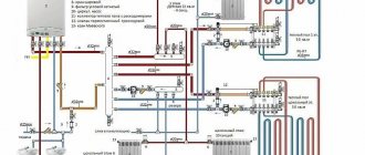
Connection diagram for a solid fuel boiler to a closed heating system
Scheme of a closed heating system with a solid fuel boiler.
1 - boiler safety group (safety valve, automatic air vent, pressure gauge); 2 — tank with a supply of water for cooling the coolant when the boiler overheats; 3 - float shut-off valve; 4 - thermal valve; 5 - connection group for expansion membrane tank; 6 — coolant circulation unit and boiler protection from low-temperature corrosion (with a pump and three-way valve); 7 - heat exchanger for protection against overheating.
Boiler overheating protection works as follows.
When the coolant temperature rises above 95 degrees, the thermostat on the boiler closes the air supply damper into the combustion chamber of the boiler.
Thermal valve pos. 4 opens the supply of cold water from the tank pos. 2 to the heat exchanger pos. 7. Cold water flowing through the heat exchanger cools the coolant at the outlet of the boiler, preventing it from boiling.
A supply of water in tank pos. 2 is necessary in case there is no water in the water supply, for example, during a power outage. Often a common storage tank is installed in the water supply system of a house. Then water for cooling the boiler is taken from this tank.
A heat exchanger to protect the boiler from overheating and cooling of the coolant, pos. 7, and a thermal valve, pos. 4, are usually built into the boiler body by boiler manufacturers. This has become standard equipment for boilers designed for closed heating systems.
In heating systems with a solid fuel boiler (except for systems with a buffer tank), thermostatic valves and other automatic devices that reduce heat extraction cannot be installed on heating devices (radiators). Automation can reduce heat consumption during periods of intense fuel combustion in the boiler, and this can trigger overheating protection.
Another way to protect a solid fuel boiler from overheating is described in the article:
Read: Buffer tank - protecting a solid fuel boiler from overheating.
Continued on next page 2:
Combustion devices of auxiliary boilers, nozzles
General information
The furnace is the main part of the boiler unit in which the fuel combustion process occurs.
The combustion device includes a nozzle designed for atomizing fuel, an air guide device that ensures effective mixing of fuel particles with air entering the combustion chamber, ignition electrodes, and an inspection hole with a light filter for observing the torch during its regulation.
In ship boilers, the basic principle of organizing the combustion process is used - flare, in which fuel particles continuously move in the combustion volume in suspension along with flows of air and gases.
The advantages of the flare process include the possibility of complete mechanization of furnace maintenance and automation of its control. The furnaces in which the flare process is carried out are called chamber furnaces, meaning the chamber is the furnace space of the boiler.
A diagram of a combustion device for burning fuel oil in the furnaces of ship steam boilers is shown in Fig. 9.101.
Rice. 9.101. Combustion device for burning fuel oil.
The smallest droplets of atomized fuel oil fly into the air of the firebox from nozzle 1, forming a spray cone with an angle of 60-90°. The combustion of fuel oil droplets does not begin immediately upon leaving the nozzles, since their temperature is still lower than the ignition temperature. In this initial zone, called the flame root, intense heating, evaporation and partial gasification of the fuel oil occurs under the influence of high temperature.
To improve heating of the torch root, a diffuser 2 is installed, the cone of which protects the torch root from the flow of cold air and helps create a stable turbulence zone. The main source of heat for this initial zone is the powerful radiation of the burning torch and, to a lesser extent, the lining ring 4, as well as the recirculation of burning fuel particles -C-.
The combustion front a-b is established where the resulting combustible mixture of vapors and gasification products of fuel oil with air will have a temperature sufficient for ignition.
Droplets of fuel oil (or particles of a gasified product) move along with the air flow, so the relative speed of air washing will be low. Under these conditions, combustion will be difficult, since the penetration of oxygen molecules to the surface of the particles will be hampered by the combustion products surrounding it.
To accelerate the combustion process, intensive mixing of gas-air flows is created inside and around the circumference of the torch. For this purpose, slots are made in diffuser 2 through which primary air I flows to the root of the torch. The diffuser passes only a small amount of air, sufficient to cool the diffuser itself and the initial mixing of fuel with air.
The main amount of air - II - is supplied to the active combustion zone of the torch through air guide devices with blades 3, which ensure stable turbulence of the gas-air mixture. The throat 5 of the combustion embrasure helps direct air jets into the torch and more thoroughly mix it with flammable gases.
At full load of the furnace and steady state, the stability of the combustion of the torch is ensured both by the continuity of the supply of fuel, air and removal of combustion products, and by the high temperature developed in the torch itself.
Thus, to organize a sustainable flare process it is necessary:
- feeding heated and finely atomized fuel oil into the furnace;
- protection of the flame root from relative cold air, which must be supplied to this zone in the minimum amount necessary to begin mixture formation;
- intensive heating of the initial zone of the torch due to radiation from its active zone and thermal radiation from diffuser 2 and lining ring 4;
- intensive mixing of the products of evaporation and gasification of fuel oil with air throughout the entire thickness of the active combustion zone of the torch;
- uninterrupted supply of air and fuel to the torch and removal of combustion products;
Combustion devices for burning fuel oil, which provide the above conditions, are discussed below.
In Fig. Figure 1 shows a simple design of a combustion device with a steam or air nozzle. Air is supplied to the firebox through the blower in the air box 3 and only in small quantities through the hole in the pediment, which houses nozzle 1. The amount of air is regulated by the blower door 2. Air is supplied to the firebox by a fan under a pressure of 30-40 mm of water. Art.
Figure 2 shows a typical design of the combustion device of a Scottish-type boiler.
Positions in the figure: 1 - shaped brick masonry; 2 - simple brickwork; 3 — air box; 4 — lever for regulating air supply to the firebox; 5 - main air damper; 6 - nozzle; 7 — secondary air supply location; 8 - inspection hole.
The combustion device of a water-tube boiler with a steam-mechanical nozzle has the following design features: the steam pressure in front of the nozzle is 0.1-0.15 MPa (nozzle with external mixture formation); when changing the fuel supply by the injector, no change in the pressure of the atomizing steam is required; nozzle adjustment depth 15:1; the nozzle cannot be removed from the socket without first turning off the fuel and steam supply. An interlock is provided so that the fuel valve handle cannot be turned to the open position until the atomizing steam supply valve is open and, conversely, the steam supply cannot be closed until the fuel supply valve is closed. ; If the fuel supply valve is closed and the steam supply valve is open, steam is used as a cooling medium. In this state, the nozzle cannot overheat and is ready for immediate use.
Fig. 4. Design of a combustion device with a mechanical centrifugal nozzle 1 and a two-zone air guide device 5. The nozzle nozzle (and therefore the torch root) in this case is significantly removed from the outlet section -A- of the combustion lance, which leads to the formation of carbon deposits on the inner ring of the air guide devices. To remove carbon deposits, a special ring 3 with a handle is provided. The primary swirl of air is carried out by blades 6, which are turned by handle 2.
In the peripheral zone of the air guide device, the degree of air swirl is reduced by blades 4, and air jets in this zone push the torch away from the walls of the tuyere and then enter the main zone of the torch. There is a valve (flap) designed to prevent gases from the firebox from entering the boiler room when the nozzle is removed.
Fig. 5. Combustion devices with profile rotary blades, in which both conventional mechanical nozzles and steam-mechanical ones can be used. Air for fuel combustion is supplied by a blower fan to box 1, where the air directing devices of the injectors are located. This design has eight dampers 4 with profile blades 2 having a curved surface that creates rotational air movement. The dampers are closed and opened manually using a handle that moves the ring 8. Pins 9 are welded to the ring, with the help of which the clamps 7 are rotated, rigidly connected to the leading pins 6 of the dampers 4. The rings move along the rollers. The inlet cone 5 is connected to the main part of the VNU with coupling bolts 3. The nozzle barrel 14 is placed in a pipe 11, which ends with a diffuser 13, which protects the root of the torch from being cooled by air. On the outer flange there is an inspection eye 12, through which you can observe the quality of fuel oil combustion.
Fig. 6. Design of an air guide device with fixed blades 2 located tangentially to the circle. Air from the box 9 enters the channels formed by the blades 2, and then in the form of a swirling flow is supplied to the tuyere 1, where it is mixed with atomized fuel oil. The air guide channels are blocked or opened by a cylindrical damper 3, which moves automatically by a servomotor, to which the damper is connected by a rod 4. When the nozzle barrel is removed from the pipe 5, the flap 8 prevents the release of hot air. The diffuser 10 is moved manually by a rod 6 secured by a stopper 7.
Figure 7. Auxiliary boilers of diesel ships are often equipped with Monarch-type combustion devices. The combustion device is a unit that consists of two spray nozzles 6: the main working and duty (ignition) nozzles, arranged in one head. In front of each of the two nozzles there are magnetic shut-off valves 7 and 8. The fuel pump 10 and fan 1 are mounted on the same shaft by a rotating electric motor 2. Fuel from the supply tank flows by gravity through pipe 9 to pump 10 and is directed along the pressure line to solenoid valves 7 and 8 The nozzle is equipped with an electric ignition device 3 and ignition electrodes 5. The internal parts of the combustion device are located in the housing 4. The combustion device is an element of the boiler automatic control system based on steam pressure. The fuel supply is regulated either by turning off the nozzles or by draining part of the fuel into the receiving part of the pump 10. The boiler performance is regulated by turning off one or both nozzles using steam pressure sensors connected to the solenoid valves 7 and 8.
Fig. 8. Combustion device of auxiliary boilers of motor ships with a rotating nozzle of the “Saake” type. The main part of rotary nozzles is a spray cup that rotates at high speed. The spray cup and the fan are located on the same shaft, driven by an electric motor using a belt drive. Fuel with a temperature of 70-90°C and a pressure of 0.07-0.15 MPa enters the internal channel of the nozzle rotor and then onto the inner walls of the glass rotated by an electric motor at a speed of 4500-5000 rpm. The primary air supplied by the fan enters through the air duct to the annular slot. Secondary air enters through the cavity. Under the influence of centrifugal force, the fuel is evenly distributed over the inner surface of the glass. The air from the first stage fan flows concentrically around the glass and, running into the fuel film, breaks it into tiny droplets, which mix with it, ensuring a normal combustion process. The primary air pressure is 350-400 mm water. Art.; secondary 30-40 mm water. Art.
Fig. 9. For higher intensification of the flare process of burning fuel oil, a nozzle arrangement is used in the upper part of the combustion chamber. In this version of the nozzle arrangement, the mixing gas-air flows received a more efficient movement from top to bottom, thus ensuring almost complete distribution of the torch throughout the volume of the furnace. At the same time, the stability of the torch combustion increases in conditions of almost complete absence of brickwork.
Positions in the figure: 1 - retractable ignition device; 2 — servomotor of the main air damper; 3 — flame presence sensor; 4 — place for supplying fuel and steam; 5 - main air damper; 6 - flame stabilizer.
Similar articles
- Fittings for ship auxiliary boilers
- Combined recovery boilers
- Marine recovery boilers, purpose, design
- Vertical combination boiler of the Shukhov system
- Auxiliary double-circuit boiler
- Auxiliary water tube boilers
- Auxiliary fire tube boilers
- Classification of ship auxiliary boilers
- Main indicators characterizing the boiler
- Purpose of the auxiliary boiler installation and its diagram
Rating 0.00 (0 Votes)
Installation progress of a solid fuel boiler
Despite progress in the field of electrification and gasification of the country, there are still many places where these communications are practically absent. But even where they exist, many people prefer to install autonomous heating and hot water supply in their homes.
To do this, a solid fuel boiler is installed, which allows you to get heat and hot water in a private house, cottage or summer house with much lower operating costs and financial investments. The choice of this type of equipment is quite large, but all of it has fairly clear connection diagrams for various types of heating.
From theory to practice
More often, those who want to make equipment with their own hands opt for a vertical solid fuel boiler. The manufacturing process will be considered using the example of a solid fuel boiler for heating a house with an area of 100 m2. This system consists of seven radiators and a plumbing system.
So, let's make a heat exchanger:
- We manufacture vertical bases for the heat exchanger. To do this, we take four profile pipes, each 30 cm long, which will be located on the side of the combustion chamber;
- We make four holes in them with a diameter of 5 cm using a gas cutter. We remove irregularities with an angle grinder (grinder). There should be eight holes;
- in the pipes that will be located at the back of the equipment, we make four holes with a diameter of 40 mm and four with a diameter of 50 mm. All of them should be located on the side connected to the front pillars. The result should be eight holes;
- in a profile pipe 500 mm long, we cut out a hole for attaching a pipe through which waste water will be discharged;
- We make a hole in the upper part of the rear pillar to supply water to the system.
Then we proceed to assembling the heat exchanger. The vertical bases are connected by a profile pipe. To do this, we place it on bases installed perpendicular to the surface. We weld the joints. We connect this entire structure on the reverse side with a profile pipe with holes for water drainage. As a result, we get the front wall of the heat exchanger.
Next, we install the vertical bases perpendicularly and weld them with four round pipes. This turns out to be the rear wall of the heat exchanger. We connect the front and back walls together. To do this, you need to bring the longitudinal pipes to the holes and weld them, and then weld the pipes for supplying and discharging water to the structure. We weld the joints using pieces of metal and check the strength of the heat generator.
After checking the strength of the weld, close the water drainage pipe with a plug, and pour water into the inlet hole. We check the tightness of welding joints for visible leaks.
Making the case will also require effort. To do this, we cut out eight walls from sheets of heat-resistant steel - 2 front, 2 rear and 4 side. The area of each of them should be 850 x 300 mm. We take all measurements using a meter ruler and cut the material with a grinder. Then we cut out two plates measuring 450 x 450 mm: one for the bottom, the other for the top plate of the boiler.
We make two holes for the doors in the front wall: the first - at the level of the grate for igniting the fuel and cleaning the combustion chamber, and the second - a little higher level for loading fuel. In our work we use a drill and a grinder. From the sheet we cut stiffening ribs 80 cm long.
Rules for organizing solid fuel heating
The main difference that a heating system with a closed-type solid fuel boiler has is the type of fuel used. Coal, firewood, peat or fuel briquettes are used as energy carriers. All of them are characterized by high energy intensity and, as a result, intense heat release.
In order to make heating with a solid fuel boiler with your own hands, you will need to familiarize yourself with the rules of its organization. They directly depend on the chosen scheme, the pipe distribution system and the coolant used.
A characteristic feature is the correct installation of heating with a solid fuel boiler. The source of thermal energy and fuel must be located in different rooms, and in addition to the installation rules, safety measures for the operation of heating must be observed.
The basic rules for the design and practical implementation of heating systems using solid fuel boilers and stoves are the following:
- Use of non-combustible materials. When installing a stove or boiler, the floor, walls and ceiling in the chimney area must be fireproof. Those. if exposed to high temperatures, these materials should not spontaneously ignite or smolder;
- Work stabilization. The main danger when operating a solid fuel boiler for water heating is overheating of the water in the heat exchanger. To prevent this, the boiler or stove provides the ability to regulate the air supply necessary to maintain the combustion process of wood. This could be a system of valves connected to a mechanical temperature controller;
- Supply and exhaust ventilation. The classic installation scheme for heating from a solid fuel boiler provides for air exchange in the room where the equipment is installed. When it operates, combustion products will inevitably enter the room. Supply and exhaust ventilation will remove them, thereby preventing CO2 concentrations that are dangerous to humans.
Factory-made or home-made solid fuel heating boilers should be installed in separate boiler rooms. Exceptions are models with low power, which are equipped with a hob. But even in this case, all safety measures must be ensured in the kitchen.
The basic rules for arranging boiler rooms in which double-circuit solid fuel heating boilers will be installed are described in SNiP II-35-76. Before installing the equipment, you should read this document.
Types of fireboxes
Types of fireboxes
A mechanical firebox is a layered combustion device with a grate, in which the necessary maintenance operations are performed using certain mechanisms. As you know, there are three such operations:
- feeding the layer with fuel;
- peeling the layer;
- removal of slag.
The screwing operation is not required for some fuels or can be avoided.
A firebox can be considered fully mechanical only if all maintenance operations are 100% mechanized. If some portion of manual labor remains, then the firebox should be classified as semi-mechanical. It is important that the mechanization means operate automatically and do not require special control of the stoker based on visual observation.
There are types of shaft-type fireboxes with natural movement of the fuel layer under the influence of gravity; they are mechanized, but cannot be called mechanical, since they are devoid of mechanisms. They can only burn non-coking and non-slag fuels with a low ash content (wood, tree bark and sod peat). These types of fireboxes are not discussed in this book.
Fireboxes do not include external mechanisms for supplying fuel to fuel receiving funnels (before the feeders) and for removing slag from slag bunkers (excluding those that are integral with the fireboxes).
Currently, the following types of fireboxes are used in different countries:
- fireboxes with chain grate;
- fireboxes with push-over grates;
- bottom feed fireboxes;
- fireboxes with a rustling strip;
- ring fireboxes;
- fireboxes with vibrating grate;
- fireboxes with throwers.
The first three named groups of combustion devices came into practice a long time ago, the rest began to spread over the past 20 years. The use of different types of fireboxes varies in individual zones and countries of the world, which is determined, on the one hand, by the presence of certain types of fuels, and on the other hand, by the unique direction of technical thought and the habit of a certain organization of the combustion process.
Chain grate firebox types are common wherever high quality coals are available. Types of fireboxes with pushing grates were widely developed in pre-war Germany and some neighboring countries, since one of the main fuels was relatively low-ash brown coal. In the USA, which has moderately caking bituminous coals, bottom-feed combustion devices were predominantly used for a long time. Types of fireboxes with throwers, with a rustling bar, annular and with a vibrating grate appeared in connection with the use of degraded types of fuel, on which other combustion devices could not work.
There are new proposals regarding layer combustion. Thus, in France the type of firebox with a fluidized bed is advertised; We are at the stage of pilot industrial development of a combustion device with an inverted bed on a grid of water-cooled pipes.
Abroad, mechanical fireboxes are very diverse in design. This, of course, is explained not only by the desire to provide the best conditions for burning fuel, but also by patent and competitive considerations of numerous companies manufacturing combustion equipment. A number of firebox designs are too complex, which makes their operation and repair difficult.
In our conditions, a wide range of combustion equipment cannot be useful. In order to unify boilers, as well as reduce the cost of manufacturing fireboxes, it is important to select a limited number of types of fireboxes for production.
Based on the development trends of our and foreign boiler construction that have emerged over the past 20 years, we can formulate the following requirements that mechanical furnaces must satisfy in modern conditions.
- Ensuring complete mechanization and automation of fuel combustion;
- The ability to implement rational layouts with modern small-sized and block boilers (without lifting the latter and without creating an ash floor or basement in the boiler room);
- Greater fuel versatility. In this regard, types of fireboxes are allowed only for the following purposes:
- for all hard coals (including highly caking ones);
- for all brown coals (including high-moisture and high-ash coals);
- for anthracite;
- for sod peat;
- for slate;
- for wood, tree bark and agricultural waste.
Simplicity of the device, low metal consumption, low cost, high operational reliability, long service life and ease of repair. Meeting all these requirements is a very difficult task. It can be solved both by improving existing types of fireboxes and by creating fundamentally new designs.
How to choose the right boiler connection diagram
In order to keep the house warm, it is not enough to know what heating schemes are available with a solid fuel boiler. Craftsmen who have been creating heating systems for many years give the following recommendations:
- When creating a drawing of a heating circuit for a solid fuel boiler, you should first familiarize yourself with the types and operating principles of such heat generators. This can be a constant or long-burning heater, a pyrolysis or pellet unit, or a buffer. Each of these devices has its own operating criteria, which may be disadvantages for some, and advantages for others.
- To get an ideal heat supply scheme, you need to be able to combine the functioning of the boiler with the tank, since this element accumulates thermal energy. This is justified by the fact that the element heating the water can change its temperature in the range from 60 to 90 degrees. There is no constant indicator. Since solid fuel boilers are inert devices, this distinguishes them favorably from gas, diesel and electric analogues.
- When choosing a heating scheme, you need to objectively assess the risk of power outages. If there are frequent power outages in the area, then a system with a water pump will not only not pay for itself, but may quickly fail. Therefore, it is better to choose a type of heating with natural circulation.
- When choosing a piping, it is worth considering in advance the safety lines between the boiler and the tank. They are located at the points of the inlet and outlet pipes so that they are as close as possible to the water heater. Also, to achieve maximum effect, you need to try to keep the distance between the boiler and expansion tank to a minimum. But it is no longer possible to install safety valves or taps here.
- If a scheme with a pump was chosen, then it is installed on the return pipe, as close as possible to the heat generator. Thus, even if the lights are turned off and the pump stops working, the water will continue to move along the circuit, that is, minimal heat will be retained. The device must be installed along a bypass route. Only then will it be possible to disconnect it from the network (if necessary), and shut off the circuit itself using taps.
- There is such a thing as bypass. These are jumpers with taps that are placed between the supply line and the return pipe. This arrangement facilitates the return of “extra” hot water when the volume changes through the thermostat.
- A stainless steel valve must be installed in the chimney pipe. Since there is moisture in the smoke, albeit in small quantities, it is this that can provoke the destruction of the internal part.
Tying is a process that deserves special attention. Therefore, they design and install it only if they have complete confidence in their abilities.
Nikolay Avramenko, 51 years old, Energodar
Having read the article, I would like to add my note. The topic of operational characteristics of solid fuel boilers was touched upon here. It was indicated that they have such a feature as high inertia. I would like to say that this phenomenon is not typical for pellet boilers. This is due to the fact that such devices have a burner that receives wood pellets in portions. Therefore, when the supply of raw materials stops, the flame immediately goes out. Although such boilers are not so cheap.
Anton Abramov, 29 years old, Omsk
At one time, I was interested in the work of solid fuel boilers, as they offered me a position related to this area. I would like to leave a few words about the thermostat and its regulatory features. You need to understand that when a certain temperature is set, for example, at 85 degrees, even though the damper is closed, the burning and smoldering continues. Because of this, the water still heats up a couple of degrees, and only then it will be established accurately. Therefore, you should not turn the thermostat back and forth, otherwise this may lead to breakdown of the entire system.
Nikita Karpenko, 37 years old, Arkhangelsk
When we built a house outside the city, we planned to live there all year round. The time came when it came to heating, and I settled on a closed-type system with natural circulation. Firstly, it was quite easy for me to create it with my own hands, and secondly, we were already a little limited in money. I didn’t have any particular problems with the installation, but when the first cold weather arrived, I realized that there was clearly not enough heat for the house. So at school, I was quite good at physics, and I realized that heat is “lost” in areas where the pipes were left open. Taking a roll of mineral wool, I wrapped all the pipes that run in open areas. Literally by the end of the first day, our family felt a significant warming in the rooms. Therefore, you need to remember such moments.
Boiler firing process
General rules
Before starting to operate solid fuel boilers, you must:
- inspect boiler fireboxes, flues, chimneys and, if necessary, repair them;
- Heating devices that have become unusable (furnace and blower doors, valves, views, cleaning doors, grates, etc.) should be repaired or replaced with new ones;
- eliminate all leaks in the sealing areas of doors and valves;
- clean chimneys of soot and ash;
- study the instructions on the rules for caring for solid fuel boilers and their fireboxes.
Before lighting a solid fuel boiler, it is necessary to warm up the pipe by burning dry shavings or wood chips and eliminate smoke from the stove. The use of kerosene, gasoline and other flammable liquids for lighting solid fuel boilers is strictly prohibited. When there is a strong draft in the boiler, it is recommended to light the kindling with the pipe valve closed and open it after the kindling has ignited.
It is not recommended to simultaneously heat several solid fuel boilers located in adjacent rooms and connected to one common chimney. This can lead to loss of draft in boilers, as well as to their smoking. When firing a solid fuel boiler with low draft in the pipe, all exhaust openings in the rooms must be closed.
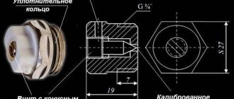
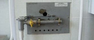
To ensure uniform combustion of the fuel, unburned fuel particles should be raked onto the grate. It is forbidden to fire solid fuel boilers with the combustion door open; this leads to large heat losses and burnt fuel. To avoid the loss of people due to premature closure of the pipe, a hole with a diameter of 15 mm must be made in the valve and in the view (Figure 1).
In the picture, a hole with a diameter of 15 mm is drilled in the bolt of the valve.
The pipe of the solid fuel boiler closes when the coals burn completely and the blue light above them disappears.
When cleaning the firebox, unburned fuel (coal, briquettes, etc.) is removed from the slag and reused to fire the boiler.
In solid fuel boilers you can burn various types of fuel - firewood, peat, hard and brown coal, briquettes and various fuel wastes. This requires that the furnace equipment correspond to the types of fuel actually used and that it is in full working order.
Wood burning
Wood can be burned in almost all solid fuel boilers. Firewood for heating boilers must be chopped and as dry as possible - this is the main condition in order to obtain the required thermal effect from a solid fuel boiler. To speed up the drying of wet firewood, you should first split it.
When placing firewood in the firebox, it is necessary that there is a free space of at least 200 mm high above the firewood, up to the top of the firebox.
It is recommended: stack the logs in the firebox tightly one to the other; immediately lay at least half of the portion of firewood, and throw the rest as it burns out in one or two steps, depending on the amount of fuel and the capacity of the firebox.
For uniform combustion of firewood, it is necessary to remove it two to three times per firebox, doing this quickly, without cooling the boiler.
Furnace with peat
Peat combustion is possible in all solid fuel boilers that burn wood. Before starting to fire the boiler, it is necessary to: clean the firebox from ash; close the ash chamber and open the combustion door; place a layer of peat on the grate and on top of it kindling from finely chopped firewood weighing 0.3–0.5 kg; Place peat up to 200 mm thick on top of the kindling; open the valve to approximately 2 sections of the gas duct.
After this, light the kindling. As soon as the peat begins to ignite, open the blower door and close the furnace door. The remaining portions of peat should be thrown into the firebox as needed, doing this quickly, and before throwing in the next portion of peat, the previous layer must be leveled, knocking down the ash so that the peat burns evenly.
Before finishing the fire (with hermetically sealed doors), close (screw) the fire and ash doors tightly; With ordinary doors, you should almost completely close the blower door, and close the pipe with a valve for 2 sections of the gas duct.
Coal fire
Combustion of coal is permitted in heating boilers adapted to operate on this type of fuel.
For the combustion of coal in a solid fuel boiler, the best firebox is a shaft with vertical walls, equipped with a grate. It is desirable that the firebox has a greater height. In particular, for burning anthracite, this height from the arch (overlap) of the firebox to the level of the grate should be up to 50 cm. In heating and cooking stoves of the “Swedish” type, for kitchen stoves with cast iron slab flooring, it is necessary to reduce the height of the combustion space to the possible minimum, since with a high firebox height, the cast iron flooring will not warm up well. The normal distance between the combustion and ash doors for anthracite is considered to be 21 cm, and at least 14 cm. When converting fireboxes for coal, these distances must be adhered to.
Furnace and ash doors must be cast iron and sealed. The grate for anthracite must be cast iron with developed ribs, thanks to which it cools well and does not burn out. It is recommended to have the following dimensions of furnace appliances: combustion doors - 205 X 250 mm; ash doors – 140 X 250 and 140 X 130 mm; gratings – 205 X 300 and 205 X 350 mm; grate bars – length 275, 300 and 350 mm.
The firebox of a solid fuel boiler equipped for coal is suitable for burning other types of fuel. Before starting to light a wood-burning boiler, it is necessary to: clean the firebox of ash, slag and unburnt coal; lay kindling from wood chips or finely chopped firewood, weighing about 1.4–1.5 kg. The kindling is laid out on the grate and ignited with the pipe valve slightly open.
When the kindling flares up, the pipe valve opens completely and the first portion of finely chopped coal is thrown in an even layer of 50–80 mm over the entire grate. After this, close the combustion door and open the ash chamber. When the coal flares up, throw in the first portion to a layer thickness of 120–200 mm.
When subsequently adding fuel, the following requirements must be met: throw in new portions of coal when the previous one flares up well enough; each time coal is thrown in, which involves opening the combustion doors, the ash door should first be closed; Make sure that the fuel does not burn down to the grate and burns throughout the entire mass in an even layer.
If there are fines or dust in the coals, they should be moistened with water before throwing them into the firebox. Fat, highly caking coals of the PZh and Zh grades, consisting of fines, are usually moistened abundantly so that the coal particles stick together, without allowing excess water.
Steam-caking coals of the PS grade and low-caking coals of the SS grade are mostly small and require moderate wetting.
Lean coals of grade T, usually consisting of fines and prepared for throwing into the firebox, are moistened until the entire mass is wet. Long-flame coals are wetted only enough to reduce dust formation.
Anthracite does not require wetting; sometimes, with a large content of small particles, it is moistened to reduce dust emission.
During combustion, the combustion door should be kept closed, opening it only while adding a fresh portion of fuel.
During combustion, the coal should be stirred as little as possible to avoid excessive cooling of the firebox, large failure of coal through the grate and mixing it with slag. With high-ash brown coals (Moscow Region, Chelyabinsk, Central Asian, etc.), on the contrary, the drilling must be done more often, otherwise the pieces of coal will “ash” and go out. The throwing of these coals should be done more often and in small portions.
When the fuel burns out, you should close the ash door, but if the doors are sealed, it can be closed.
When the fuel layer reaches 30–40 mm, the ash door should be closed completely, and the pipe should be closed with a valve at ? sections of the gas duct. It is necessary to completely close the chimney when the coals burn completely.
Closing the pipe prematurely can lead to death.
To kindle anthracite, it is recommended to use finely chopped dry firewood, and coal should be chopped into pieces ranging from 30 to 50 mm in size. The first portion of anthracite is thrown onto the burning kindling in an even layer 50–70 mm thick. After 15–20 minutes, when the anthracite flares up, a second portion is thrown in so that the total thickness of the layer is brought to 250 mm, and then the firebox is carried out in the same way as with coal.
Fire briquettes
Coal and peat briquettes are good fuel for a solid fuel boiler.
Before starting to fire a solid fuel boiler, prepare its firebox in the same way as for burning coal. The first portion of briquettes is thrown into the firebox in an even layer 100–120 mm thick. When the briquettes flare up, throw in a second portion to a thickness of 150–180 mm.
When subsequently throwing briquettes into the firebox, the same requirements must be met as when firing a solid fuel boiler with coal.
During combustion, coal briquettes should not be screwed, and lignite and peat briquettes should be screwed as rarely as possible. At the same time, it is necessary to ensure that briquette dust, both when cleaning the firebox and when throwing and screwing, does not enter the room.
The solid fuel boiler is fired until the briquettes are completely burned. When cleaning the firebox, unburned briquettes are removed from the ash and reused to fire the stove.
Connecting emergency systems
Elements of emergency systems in the wiring diagram are used for the following purposes:
- protection against increasing the maximum operating pressure in the system;
- protection against exceeding the maximum permissible output temperature of the coolant, overheating of the boiler and heating system elements;
- preventing the formation of condensation in the boiler due to a large temperature difference of the coolant at the inlet and outlet of the device.
Safety valve
Protection of the boiler and system elements when the operating pressure of the heat-carrying liquid is exceeded is provided by a safety valve installed on the supply line at the outlet of the boiler. Such a valve can be part of a boiler safety group, which is built into the boiler itself or connected separately.
How does a safety valve work?
A drain hose is connected to the pressure relief port of the valve. When the valve is activated, excess heat-carrying liquid from the system is drained into the sewer through a hose.
Emergency heat exchanger
An emergency heat exchanger is needed to protect the boiler and system elements from overheating.
Equipment overheating can occur in two cases:
- when the power generated by the boiler exceeds that required for heat consumers;
- when the circulation pump stops working due to its breakdown or power outage.
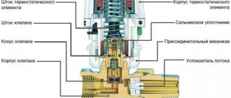
The heat exchanger consists of a cooling module and a thermal valve with a remote thermal sensor set to a certain temperature. They can be installed inside the boiler itself or separately on the coolant supply line to the heating system.
How does a heat exchanger work?
When the permissible temperature is exceeded, the thermal valve is activated by a signal from the thermal sensor.
It supplies cold water from the water supply line to the cooling module, in which excess heat is removed from the coolant. From the cooling module, the water that has removed the heat goes into the sewer system.
Additional circuit
Protection of the boiler from overheating in systems with forced circulation can also be ensured using an additional circuit with natural circulation, to which a storage tank for hot water is connected.
Boiler piping with an additional circuit
During normal operation of the system, the pressure created by the circulation pump in the main circuit closes the additional circuit using a check valve, preventing the heat-carrying fluid from circulating in it.
When the pump is turned off for any reason, the forced circulation of the coolant in the main circuit stops and natural circulation begins in the additional circuit. Due to this, the heat-carrying liquid in the system is cooled to the required temperature.
Thermostatic mixer
Maintaining the minimum required temperature at the boiler inlet to prevent the formation of condensation in it is ensured by a thermostatic mixer.
The device is installed on the return pipeline and connected to the supply line using a jumper (bypass).
Installation of a thermostatic mixer
When the temperature of the coolant in the return line is low, the thermal mixer opens and mixes hot liquid into it. After reaching the desired temperature, the thermal mixer closes and stops supplying hot coolant through the bypass to the return.
This scheme can be used in systems with any type of circulation.
Is it possible to make a solid fuel boiler with your own hands from available materials?