Calculation of thermal power
1. Determine the thermal power to heat the required volume of air. 1.1 Determine the mass flow of heated air G (kg/h) = L • р L - volumetric amount of heated air, m³/hour; p - air density at average temperature (divide the sum of the air temperature at the inlet and outlet of the air heater by two), kg/m³. 1.2 Determine the heat consumption for heating the air Q (W) = G • c • (t end - t start) G - mass air flow, kg/hour; c is the specific heat capacity of air at average temperature (add the temperature of the incoming and outgoing air and divide by two), J/(kg•°C); t start — air temperature at the inlet to the heat exchanger, °C; tkon is the temperature of the heated air at the outlet of the ventilation heat exchanger, °C.
An example of selection and calculation of a KSk air heater. Step 1
Carry out a thermal calculation and select a suitable KSk heater for heating 16,000 m³/hour from a temperature of -25°C to +23°C. The coolant is hot water with a schedule of 95°C at the inlet to the air heater, 60°C at the outlet. 1. Determine the thermal power required to heat air with a volume of 16,000 m³/hour from a temperature of -25 to +23 degrees. 1.1 Determine the mass flow rate of heated air G (kg/h) = 16000 • 1.30 = 20800 kg/h 16000 - volumetric amount of heated air, m³/hour; 1.30 - air density at a temperature of -1°C (the temperature at the inlet to the heater is -25°C plus the air temperature at the outlet +23°C - divide by two). (-25+23)/2= -2/2= -1. The density of air at a temperature of -1 has a value of 1.30. 1.2 Determine the heat consumption for heating the air Q (W) = (20800/3600) • 1005 • (23 - (-25)) = 278720 W 20800 - mass air flow, kg/hour; 1005—specific heat capacity of air at an average air temperature of -1°C, J/(kg•°C); +23 — temperature of heated air at the outlet of the heat exchanger, °C; -25 — air temperature at the inlet to the heat exchanger, °C.
| Air density depending on temperature | |||||||||||||||
| temperature, °C | -50 | -45 | -40 | -35 | -30 | -25 | -20 | -15 | -10 | -5 | 0 | +5 | +10 | +15 | +20 |
| density, kg/m³ | 1.58 | 1.55 | 1.51 | 1.48 | 1.45 | 1.42 | 1.39 | 1.37 | 1.34 | 1.32 | 1.29 | 1.27 | 1.25 | 1.23 | 1.20 |
| temperature, °C | +25 | +30 | +35 | +40 | +45 | +50 | +55 | +60 | +65 | +70 | +75 | +80 | +85 | +90 | +100 |
| density, kg/m³ | 1.18 | 1.16 | 1.15 | 1.13 | 1.11 | 1.09 | 1.08 | 1.06 | 1.04 | 1.03 | 1.01 | 1.00 | 0.99 | 0.97 | 0.95 |
| Heat capacity of air depending on temperature | |||||||||||||||
| temperature, °C | -50 | -45 | -40 | -35 | -30 | -25 | -20 | -15 | -10 | -5 | 0 | +5 | +10 | +15 | +20 |
| density, kg/m³ | 1013 | 1012 | 1011 | 1010 | 1010 | 1009 | 1008 | 1007 | 1006 | 1005 | 1005 | 1005 | 1005 | 1005 | 1005 |
| temperature, °C | +25 | +30 | +35 | +40 | +45 | +50 | +55 | +60 | +65 | +70 | +75 | +80 | +85 | +90 | +100 |
| density, kg/m³ | 1005 | 1005 | 1005 | 1005 | 1005 | 1005 | 1005 | 1005 | 1006 | 1006 | 1007 | 1007 | 1008 | 1009 | 1009 |
Calculation, selection and analysis of air heaters “online”
An air heater is one of the main elements of heating and ventilation equipment; it is the basis of installations for heating the air supplied to the room being served. If at the early stage of development of heating and ventilation technology, the development of air heaters was carried out for temperature and flow conditions, in relation to their use for heating supply ventilation air to a normal temperature of 16-18 ° C, then with the rapid development of technology, recently, the area of use of air heaters has sharply expanded. Air heaters are simply used to heat fresh supply air in ventilation units, air heating systems, heat recovery units, thermal curtains and air conditioning units. An air heater, at its core, is an air-liquid heat exchanger.
When designing heat exchangers, developers usually pay special attention to achieving high specific thermal performance indicators, increased rated power and subjective consideration of the real needs of consumers.
To determine the design of the air heater, it is necessary to know the amount of air passing through the air heating unit, the air temperature at the inlet to the unit, as well as the flow rate of the coolant and its temperature at the inlet and outlet of the heat exchanger.
The air heating unit can be configured with one or several heat exchangers. The first case is common in aggregated installations, when the manufacturer of the ventilation unit produces a unit already equipped with an air heater, which is selected by the manufacturer according to the requirements of the consumer (designer). In the second case: the air heating installation is assembled by the designer himself, and he himself must select the model, standard size, number of heat exchangers, as well as acceptable aero- and hydrodynamic characteristics, the required heating surface margin, etc.
Air heaters are simply used to heat fresh supply air in ventilation units, air heating systems, heat recovery units, thermal curtains and air conditioning units. An air heater is essentially an air-liquid heat exchanger
The source of heat for heating ventilation air is mainly heat supply systems that release heat throughout the year according to certain temperature schedules, taking into account the temperature of the outside air, but at the same time limiting the temperature of the return coolant returned to the consumer.
In addition to the thermal technical selection of the heater, a conscientious designer is interested in the amount of heat exchange surface reserve, the air and coolant velocities, aero- and hydrodynamic resistance, the outlet temperature of the coolant, the deviation of the outlet air temperature when changing the coolant parameters, the possibility of placement in the available space, etc.
For example, if the surface reserve is slightly different from the recommended values, and the initial data are determined correctly, then a professional interest arises: what temperature of the coolant is expected at the outlet of the air heater? Or, conversely, what temperature must be provided for the coolant at the inlet to the air heater in order to obtain the coolant at the initial temperature at the outlet?
Sometimes it doesn’t seem superfluous to carry out a similar check on air parameters. Since when designing air heaters, special attention is paid to obtaining high thermal performance, and air heaters in installations are used in ventilation and air conditioning systems not only for purely ventilation purposes, but for heating the supply outside air, the designer may have other kinds of wishes.
All this is excluded when using aggregated equipment, when the selection of a heater is carried out by an object that does not know the design features, and due to the lack of precise technical characteristics of the object, such selection is not possible.
In this case, the designer’s responsibility for the compliance of the selected equipment with those issues that may arise under operating conditions is reduced. All of the above indicates the need to provide the designer with the opportunity to participate in assessing the eligibility of the installation of specific equipment selected by the manufacturer.
Assessing the efficiency of carrying out hydraulic calculations of pipelines of heating systems [1] and the possibility of influencing the choice of operating mode, the value of hydraulic resistance, etc. It seemed appropriate to the author to disseminate the experience of using the modern spreadsheet editor MS Excel for the selection and design of air heaters for ventilation systems (Fig. 1 and 2).
The procedure for thermal technical calculation of an air heater, the choice of its standard size and analysis of operation under possible deviations of temperature operating conditions from the calculated ones will be illustrated using the example of air heaters from the Kostroma Heating Plant [2], which produces air heaters (water air heaters) of about five modifications and each modification of at least 14 standard sizes. In this diversity, it is difficult to decide which air heaters to choose, doing this according to factory recommendations, which are not much different from those given in reference and educational literature.
The entire process of organizing calculations, selection and analysis of the operation of air heaters in MS Excel can be organized on two sheets: on the first sheet (Fig. 1) there are technical characteristics of all modifications and standard sizes produced by the air heater plant - this data is entered for each manufacturer. Cells with technical characteristics and calculation results for each air heater are located in one line. This sheet must be protected and hidden so that the connections and data entered into it are not accidentally destroyed or distorted. In Fig. 1 tamper-protected cells are marked with a gray background. In the cells to the right of the technical characteristics there are cells with the results of calculations of intermediate and final physical quantities that determine the thermal technical process of work.
Cells with technical characteristics and calculation results are located in one line.
If you want to take into account models and standard sizes of other manufacturers, you must copy the lines of the standard sizes already used and make changes to the contents of the copied cells (representing technical data) for similar data on air heaters from the new manufacturer.
In Fig. 2 shows the main sheet. He is the one who is the worker. The initial data for which the air heater is selected is entered here, and the limitations on the physical parameters of the air heater that are permissible during the calculation are determined here. These include, first of all, the heating surface reserve, air mass velocity, and coolant velocity. If desired, you can take into account restrictions and other physical parameters. In the example article, restrictions are introduced only on the three parameters given above. In Fig. Figure 3 shows on an enlarged scale the entry of source data into the table. The cells highlighted in yellow are filled in in the table. As soon as this is completed, all cells of this sheet will be automatically filled, a fragment of which is shown in Fig. 6.
Note that these will be the results of selecting a single heat exchanger. The ideal case is when three “YES” appear in the “constraint satisfaction” columns (for the case depicted). This is the KSk3-9 heat exchanger for this selected case, the heating surface reserve is 7%, the mass velocity is 6.11 kg/(m2-s), the coolant velocity is 1.56 m/s, that is, all data lies within the limits of the limitations we have accepted. Here, due to illustrative features, we consider only the KSk... 02HL3B heat exchanger models, but it is possible to find a heat exchanger that satisfies our restrictions in other models produced by the plant and presented in Fig. 2. Thus, based on the percentage reserve of heat exchange surface from the entire variety of heat exchangers produced by the plant, eight air heaters can be recommended for use (KSk3-9 02HL3B, KSk4-7 02HL3B, KSk3-10 50AU3, KSk4-7 50AU3, VNV 113-404 01U3, VNV 123-403 01UT3, VNV 123-310 50AT3, VNV 123-407 50AT3.) The underlined standard sizes satisfy all the restrictions we have specified: in terms of heating surface reserve, in air mass velocity, in coolant velocity.
Sometimes an air heating installation must be composed of several heat exchangers. In this case, it is necessary to decide on the design of the installation: how many heat exchangers are installed in parallel, how many in series - both for air and coolant
Let’s assume that heat exchangers that meet all the requirements are not suitable for us for some reason. Then, analyzing the calculation results in the table, allowing for some deviation from the mass velocity limit for the installation, you can accept the KSk4-7 heat exchanger (from the heat exchangers listed above). It will be smaller in frontal size, but somewhat thicker along the air flow. It is possible that when considering all types and models of heat exchangers produced by the plant and presented in Fig. 2, other air heaters may also be suitable.
It should be emphasized here that with this method of calculating heat exchangers in the table in Fig. 6 shows all the physical quantities that determine heat transfer, the designer can quite consciously make the final choice of the heat exchanger.
Having thus chosen a modification and size of the heat exchanger that does not satisfy all the restrictions, the designer can analyze what the coolant temperatures will be if the calculated heat exchange surface is close to the true one. To do this, refer to the table in Fig. 7. In the line of the selected heat exchanger, in the yellow cells, set one of the temperatures T1 or T2 constant, and change the other and select it until the value in the “Percentage” column is close to zero. Depending on the desired accuracy and experience, this process will require two or three attempts.
Sometimes an air heating installation must be composed of several heat exchangers. In this case, it is necessary to decide on the design layout of the installation: how many heat exchangers are installed in parallel, how many in series - both for air and for coolant. This data is reflected in the row of a single heat exchanger, in the yellow cells of the table in Fig. 5 “Heat exchanger connection diagrams”, using the recommendations given in Fig. 4.
Note that the table cells in Fig. 5 at the beginning of the calculation of heat exchangers should always contain the parameter “1”, since initially the calculation is made for one heat exchanger, and only then, when it turns out that not a single heat exchanger is suitable, the layout diagram of the air heating installation should be selected. For any scheme, the methodological choice of installation is no different from that outlined for a single heat exchanger.
When configuring an air heating installation from several heat exchangers, it should be borne in mind that a doubling of the coolant velocity affects the heat transfer coefficient by only 10%.
Here we consider options for selecting air heaters under three restrictions, but it is not difficult to increase the restrictions, for example, on the values of aerodynamic and hydraulic resistance. Each more or less suitable option can be copied on the “Initial Data” sheet, and a general list of heat exchangers that can be used in the designed installation can be compiled.
By analyzing calculation data for all heat exchangers produced by the plant, the choice of heat exchanger can be made consciously, and not formally:
1. Based on the percentage parameters, you can judge whether it is worth installing one or two heat exchangers, and at the same time roughly assess the feasibility of one or another KSk or VNV model. What standard sizes are appropriate for this purpose - in which the percentage of heat exchange surface reserve is negative or less than the minimum limited value.
2. The choice of air heaters with a large reserve of heat exchange surface entails a decrease in the temperature of the coolant at the outlet, a decrease in the flow rate and speed of the coolant. Choosing a heat exchanger with a reduced heat exchange surface has the opposite effect (the temperature of the coolant at the outlet increases, its speed increases).
3. If it is impossible to select a heat exchanger with a margin within acceptable limits, then it is possible to determine the temperature range of the coolant in which the air heating installation will operate, and thereby assess the degree of possible freezing, as well as the required design diagram of the air heating installation.
It should be noted that the choice of an air heater with a large reserve of heat exchange surface entails a decrease in the temperature of the coolant at the outlet, a decrease in the flow rate and speed of the coolant. Choosing a heat exchanger with a reduced heat exchange surface has the opposite effect
Thus, using the example of calculation, selection and analysis of the operation of an online air heating unit, the features of the calculation and the advisability of rationalizing your design and calculation work using basic calculations in MS Excel are illustrated.
Anichkhin A.G. Design of heating systems in MS Excel // S.O.K. Magazine, No. 3/2011. Recommendations for the selection of air heaters and air heaters. - Kostroma: OJSC "Halor Plant", 2002.
Frontal section
2. Selection and calculation of air heaters - stage two. Having determined the required thermal power of the air supply unit’s water heater to heat the required volume, we find the frontal cross-section for air passage. Frontal section is a working internal section with heat-dissipating tubes through which flows of forced cold air directly pass. f (m²) = G / v G - mass air flow, kg/hour; v - mass air velocity - for finned heaters is taken in the range of 3 - 5 (kg/m²•s). Acceptable values are up to 7 - 8 kg/m²•s.
An example of selection and calculation of a KSk air heater. Step-2
Select a suitable KSk supply ventilation air heater for heating 16,000 m³/hour from a temperature of -25°C to +23°C. The coolant is hot water with a schedule of 95°C at the inlet to the air heater, 60°C at the outlet. 2. Calculation of the frontal cross-section for air passage. We select the required cross-sectional area of the KSk heater for a mass air flow of 20800 kg/hour. We take the mass velocity to be 3.6 kg/m²•s. f (m²) = (20800/3600) / 3.6 = 1.605 m² 20800 - mass air flow, kg/hour; 3.6—air mass velocity, kg/m²•s. From the calculation, the required frontal cross-sectional area for air passage was 1.605 m². Next, based on the data from the table below, we select a KSk heater suitable for this section. The most suitable models are KSk 2-11, KSk 3-11 and KSk 4-11 (the frontal cross-sectional area of these heat exchangers is 1,660 m²).
Below is a table with data on two, three and four-row air heaters of the KSk-02-HL3 type manufactured by T.S.T. LLC. The table shows the main technical characteristics for the calculation and selection of all models of these heat exchangers: heating surface area and frontal section, connecting pipes, manifold and free cross-section for water passage, length of heat-heating tubes, number of strokes and rows, weight. Ready-made calculations for various volumes of heated air, incoming air temperature and coolant graphs can be viewed by clicking on the model of the ventilation heater you have chosen from the table.
| Heater name | Area, m² | Heat transfer element length (clear), m | Number of strokes through the internal coolant | Number of rows | Weight, kg | ||||
| heating surfaces | frontal section | collector sections | pipe cross-section | free cross-section (average) for coolant passage | |||||
| KSk 2-1 | 6.7 | 0.197 | 0.00152 | 0.00101 | 0.00056 | 0.530 | 4 | 2 | 22 |
| KSk 2-2 | 8.2 | 0.244 | 0.655 | 25 | |||||
| KSk 2-3 | 9.8 | 0.290 | 0.780 | 28 | |||||
| KSk 2-4 | 11.3 | 0.337 | 0.905 | 31 | |||||
| KSk 2-5 | 14.4 | 0.430 | 1.155 | 36 | |||||
| KSk 2-6 | 9.0 | 0.267 | 0.00076 | 0.530 | 27 | ||||
| KSk 2-7 | 11.1 | 0.329 | 0.655 | 30 | |||||
| KSk 2-8 | 13.2 | 0.392 | 0.780 | 35 | |||||
| KSk 2-9 | 15.3 | 0.455 | 0.905 | 39 | |||||
| KSk 2-10 | 19.5 | 0.581 | 1.155 | 46 | |||||
| KSk 2-11 | 57.1 | 1.660 | 0.00221 | 0.00156 | 1.655 | 120 | |||
| KSk 2-12 | 86.2 | 2.488 | 0.00236 | 174 | |||||
| Heater name | Area, m² | Heat transfer element length (clear), m | Number of strokes through the internal coolant | Number of rows | Weight, kg | ||||
| heating surfaces | frontal section | collector sections | pipe cross-section | free cross-section (average) for coolant passage | |||||
| KSk 3-1 | 10.2 | 0.197 | 0.00164 | 0.00101 | 0.00086 | 0.530 | 4 | 3 | 28 |
| KSk 3-2 | 12.5 | 0.244 | 0.655 | 32 | |||||
| KSk 3-3 | 14.9 | 0.290 | 0.780 | 36 | |||||
| KSk 3-4 | 17.3 | 0.337 | 0.905 | 41 | |||||
| KSk 3-5 | 22.1 | 0.430 | 1.155 | 48 | |||||
| KSk 3-6 | 13.7 | 0.267 | 0.00116 (0.00077) | 0.530 | 4 (6) | 37 | |||
| KSk 3-7 | 16.9 | 0.329 | 0.655 | 43 | |||||
| KSk 3-8 | 20.1 | 0.392 | 0.780 | 49 | |||||
| KSk 3-9 | 23.3 | 0.455 | 0.905 | 54 | |||||
| KSk 3-10 | 29.7 | 0.581 | 1.155 | 65 | |||||
| KSk 3-11 | 86.2 | 1.660 | 0.00221 | 0.00235 | 1.655 | 4 | 163 | ||
| KSk 3-12 | 129.9 | 2.488 | 0.00355 | 242 | |||||
| Heater name | Area, m² | Heat transfer element length (clear), m | Number of strokes through the internal coolant | Number of rows | Weight, kg | ||||
| heating surfaces | frontal section | collector sections | pipe cross-section | free cross-section (average) for coolant passage | |||||
| KSk 4-1 | 13.3 | 0.197 | 0.00224 | 0.00101 | 0.00113 | 0.530 | 4 | 4 | 34 |
| KSk 4-2 | 16.4 | 0.244 | 0.655 | 38 | |||||
| KSk 4-3 | 19.5 | 0.290 | 0.780 | 44 | |||||
| KSk 4-4 | 22.6 | 0.337 | 0.905 | 48 | |||||
| KSk 4-5 | 28.8 | 0.430 | 1.155 | 59 | |||||
| KSk 4-6 | 18.0 | 0.267 | 0.00153 (0.00102) | 0.530 | 4 (6) | 43 | |||
| KSk 4-7 | 22.2 | 0.329 | 0.655 | 51 | |||||
| KSk 4-8 | 26.4 | 0.392 | 0.780 | 59 | |||||
| KSk 4-9 | 30.6 | 0.455 | 0.905 | 65 | |||||
| KSk 4-10 | 39.0 | 0.581 | 1.155 | 79 | |||||
| KSk 4-11 | 114.2 | 1.660 | 0.00221 | 0.00312 | 1.655 | 4 | 206 | ||
| KSk 4-12 | 172.4 | 2.488 | 0.00471 | 307 | |||||
What should we do if, when calculating, we get the required cross-sectional area, but in the table for selecting KSk air heaters, there are no models with this indicator. Then we accept two or more air heaters of the same number so that the sum of their areas corresponds or approaches the desired value. For example, when calculating, we got the required cross-sectional area - 0.926 m². There are no air heaters with this value in the table. We take two KSk 3-9 heat exchangers with an area of 0.455 m² (in total this gives 0.910 m²) and install them in parallel over the air. When choosing a two, three or four row model (same heater numbers - have the same frontal cross-sectional area), we focus on the fact that KSk4 heat exchangers (four rows) at the same incoming air temperature, coolant schedule and air capacity , heat it on average eight to twelve degrees more than KSk3 (three rows of heat-carrying tubes), fifteen to twenty degrees more than KSk2 (two rows of heat-carrying tubes), but have greater aerodynamic drag.
Classification of air heaters according to various criteria
Air heaters are included in the design of a heating system to heat air. There are the following groups of these devices according to the type of coolant used: water, electric, steam, fire. It makes sense to use electrical appliances for rooms with an area of no more than 100 m². For buildings with large areas, a more rational choice would be water heaters, which operate only in the presence of a heat source.
The most popular are steam and water heaters. Both the first and second surfaces in shape are divided into 2 subtypes: ribbed and smooth-tube. According to the geometry of the fins, finned heaters can be plate-type or spiral-wound.
The performance of air heaters operating on a coolant such as steam is regulated using special valves installed on the inlet pipe ( )
By design, these devices can be single-pass, when the coolant in them moves through tubes, adhering to a constant direction, and multi-pass, in the covers of which there are partitions, as a result of which the direction of movement of the coolant is constantly changing. There are 4 models of water and steam heaters available for sale, differing in heating surface area:
- SM - the smallest with one row of pipes;
- M - small with two rows of pipes;
- C - medium with pipes in 3 rows;
- B - large, with 4 rows of pipes.
During operation, water heaters can withstand large temperature fluctuations - 70-110⁰. For a heater of this type to work well, the water circulating in the system must be heated to a maximum of 180⁰. In the warm season, the heater can act as a fan.
Image gallery
Photo from
According to the type of coolant involved in heating, heaters are divided into water, steam, fire and electric
Steam and water heaters are most often used in heating private, commercial and industrial facilities.
- the easiest option to install, connect and maintain, but not very rational from an economic point of view
Water heater in a production room
Steam heater on a glazed terrace
Compact electric air heater
Steam spiral-wound model
A heater is a heat exchanger that transfers the energy of a coolant to an air heating flow and works on the principle of a hair dryer. Its design includes removable side shields and heat-dissipating elements. They can be connected in one or more lines. The built-in fan provides air draft, and the air mass enters the room through the gaps between the elements.
Types of heat exchangers in heaters
Water and steam heaters can be of two types: finned and smooth-tube. The former, in turn, are divided into two more types: plate and spiral-wound. The design can be single-pass or multi-pass. Multi-pass devices have baffles that change the direction of flow. The tubes are arranged in 1-4 rows.
A heater operating on water consists of a metal, usually rectangular frame, inside of which there are rows of tubes and a fan. The connection is made to the boiler or central heating system using outlet pipes. The fan is located on the inside; it forces air into the heat exchanger. To control power and output air temperature, 2 or 3-way valves are used. The devices are installed on the ceiling or wall.
There are three types of water and steam heaters.
Smooth tube heat exchanger
Smooth tube. The design consists of hollow tubes (diameter from 2 to 3.2 cm), located at small intervals (about 0.5 cm). They can be made of steel, copper, aluminum. The ends of the tubes communicate with the collector. Heated coolant flows into the inlets, and condensate or cooled water comes out of the outlet. Smooth tube models are characterized by lower productivity compared to others.
Features of use:
- minimum inlet temperature – –20°C;
- requirements for air purity - no more than 0.5 mg/m3 in terms of dust content.
Ribbed. Due to the finned elements, the heat transfer area increases, therefore, other things being equal, finned heaters are more productive than smooth-tube heaters. Plate models are distinguished by the fact that plates are mounted on the tubes, further increasing the heat transfer surface area. In winding ones, steel corrugated tape is wound.
Bimetallic with fins. The greatest efficiency can be achieved through the use of two metals: copper and aluminum. Collectors and pipes are made of copper, and fins are made of aluminum. Moreover, a special type of finning is performed - spiral-rolled.
Mass air speed
3. Find the actual mass velocity for the selected one or more heaters. v (kg/m²•s) = G / f G - mass air flow, kg/hour; f is the area of the actual frontal section taken into account, m².
An example of selection and calculation of a KSk air heater. Step-3
Select a suitable KSk heater for heating 16,000 m³/hour from a temperature of -25°C to +23°C. The coolant is hot water with a schedule of 95°C at the inlet to the air heater, 60°C at the outlet. 3. The task is to find the actual mass velocity of the heat exchangers that we have selected. We accept KSk air heaters number 11 as the most suitable frontal cross-section for air passage (1,660 m²). Let's calculate all three models: two-row heater KSk 2-11, three-row KSk 3-11 and four-row KSk 4-11. v (kg/m²•s) = (20800/3600) / 1.660 = 3.48 kg/m²•s 20800 - mass air flow, kg/hour; 1.660 is the frontal cross-sectional area of KSk heaters taken into account, m². Since all three models have the same overall dimensions, the mass velocity in the frontal section of each air heater, regardless of the row, will have the same value.
Water consumption for heating
4. We calculate the coolant flow based on the required thermal power to heat a given volume of air. Gw (kg/sec) = Q / ((cw • (t in - t out)) Q - heat consumption for heating air, W; cw - specific heat capacity of water (supply and outlet water temperatures are summed and divided in half), J /(kg•°C); tin - water temperature at the inlet to the heat exchanger, °C; tout - water temperature at the outlet of the heat exchanger, °C.
An example of selection and calculation of a KSk air heater. Step-4
Select a suitable KSk heater for heating 16,000 m³/hour from a temperature of -25°C to +23°C. The coolant is hot water with a schedule of 95°C at the inlet to the air heater, 60°C at the outlet. 4. Calculation of hot water consumption. The coolant consumption is calculated with a temperature chart of 95°C - 60°C for heating 16,000 m³/hour from a temperature of -25°C to +23°C. Gw (kg/sec) = 278720 / ((4196 • (95 - 60)) = 1.898 kg/sec = 6833 kg/hour 278720 - heat consumption for heating air, W; 4196 - specific heat capacity of water at a temperature of 77.5 ° C ( 95°С + 60°С = 155°С / 2 = 77.5°С), J/(kg•°С); 95 — temperature at the inlet to the heat exchanger, °С; 60 — temperature at the outlet of the heat exchanger, °С.
Rules for choosing heating equipment
- For small rooms, it is recommended to use heaters whose technical characteristics allow for efficient air heating, maintain optimal temperature and do not require significant energy costs.
- It is necessary to consider not only the technical characteristics of the equipment you want to purchase, but also its level of safety. When choosing the best air heater model in your opinion, you should pay attention to the reliability of Apen Group equipment, which is completely safe to use.
- It is necessary to calculate the required volume of pumped air and temperature. To do this, you must have detailed technical characteristics of the heated room or building. We offer you equipment that has no analogues in Russia, designed for heating technical and commercial enterprises, offices and other types of premises.
We offer our services for power calculations and assistance in selecting the optimal equipment.
Examples of using our equipment
Coolant speed
5. Calculation of the speed of water movement in the tubes of the adopted heater. W (m/sec) = Gw / (pw • fw) Gw – coolant flow, kg/sec; pw—density of water at average temperature in the air heater, kg/m³; fw is the average open cross-sectional area of one heat exchanger pass (accepted according to the KSk air heater selection table), m².
An example of selection and calculation of a KSk air heater. Step-5
Select and carry out a thermal calculation of the KSk series supply ventilation air heater for heating 16,000 m³/hour from a temperature of -25°C to +23°C. The coolant is hot water with a schedule of 95°C at the inlet to the air heater, 60°C at the outlet. 5. The goal is to calculate the speed of water movement in the tubes of number 11 finned air heaters. W (m/sec) = 1.898 / (973 • 0.00156) = 1.250 m/sec - for heater KSk 2-11 W (m/sec) = 1.898 / (973 • 0.00235) = 0.830 m/sec - for heater KSk 3 -11 W (m/sec) = 1.898 / (973 • 0.00312) = 0.625 m/sec - for heater KSk 4-11 1.898 - coolant flow, kg/sec; 973 - density of water at average temperature in the heat exchanger (graph 95°C-60°C, average 77.5°C), kg/m³; 0.00156 - average open cross-sectional area of one passage of the KSk 2-11 heater, m²; 0.00235 - average open cross-sectional area of one passage of the KSk 3-11 heater, m²; 0.00312 - average open cross-sectional area of one stroke of the KSk 4-11 heater, m². 0.00312 - average open cross-sectional area of one stroke of the KSk 4-11 heater, m².
| Density of water depending on temperature | |||||||||||||||
| temperature, °C | 0 | +5 | +10 | +15 | +20 | +25 | +30 | +35 | +40 | +45 | +50 | +55 | +60 | +65 | +70 |
| density, kg/m³ | 999 | 999 | 999 | 999 | 998 | 997 | 996 | 994 | 992 | 990 | 988 | 986 | 983 | 981 | 978 |
| temperature, °C | +75 | +80 | +85 | +90 | +95 | +100 | +105 | +110 | +115 | +120 | +125 | +130 | +135 | +140 | +150 |
| density, kg/m³ | 975 | 972 | 967 | 965 | 962 | 958 | 955 | 951 | 947 | 943 | 939 | 935 | 930 | 926 | 917 |
| Heat capacity of water depending on temperature | |||||||||||||||
| temperature, °C | 0 | +5 | +10 | +15 | +20 | +25 | +30 | +35 | +40 | +45 | +50 | +55 | +60 | +65 | +70 |
| heat capacity, J/(kg•°C) | 4217 | 4204 | 4193 | 4186 | 4182 | 4181 | 4179 | 4178 | 4179 | 4181 | 4182 | 4183 | 4184 | 4185 | 4190 |
| temperature, °C | +75 | +80 | +85 | +90 | +95 | +100 | +105 | +110 | +115 | +120 | +125 | +130 | +135 | +140 | +150 |
| heat capacity, J/(kg•°C) | 4194 | 4197 | 4203 | 4205 | 4213 | 4216 | 4226 | 4233 | 4237 | 4240 | 4258 | 4270 | 4280 | 4290 | 4310 |
If two or more air heaters are used for calculation, this formula is valid only when they are connected in series along the coolant. That is, the heaters are connected in such a way that hot water, having passed through the contours of one heat exchanger, is supplied to the second, etc. When connecting, for example, two KSk air heaters in parallel for the coolant, the fw value will be 2fw, etc. For example, to heat the air we need two KSk 3-9 heat exchangers with an area of 0.455 m² (in total this gives 0.910 m²). The coolant flow rate was 0.600 kg/sec. Calculate the speed of movement of one stroke of the heaters. With a series connection along the coolant, the formula will look like - W (m/sec) = Gw / (pw • fw), with a parallel connection (the heat pipe is connected to each air heater separately) - W (m/sec) = Gw / (pw • 2fw) . Accordingly, the speed of water movement in the tubes will be greater in the first case than in the second. The recommended speed of coolant movement in water heaters of the KSk type is (0.2 - 0.5) m/sec. Exceeding this speed is associated with an increase in hydraulic resistance. Acceptable values are from 0.12 to 1.2 m/sec.
Water heater: operating principle and purpose
Water heaters are used to heat air in various rooms where there is no central heating. They are also intended for ventilation or air conditioning systems. This type of air heaters is climate control equipment that serves as a heat exchanger filled with an intermediate coolant. The coolant in this equipment is heated or hot water.
Important! If the heater is used in a climate with an ambient air temperature below 0°C, the device must be equipped with special frost protection. Otherwise, frozen water in the pipes may simply rupture them.
A steam heater differs from a water heater in that dry saturated steam serves as the coolant in the device. These are more advanced models of heaters, so the price of a heater of this class is much higher.
Operating principle of a heating coil: blue arrows - cold air, red arrows - warm air
Water air heater: features of the design and operation of the device
The water heater has a very high level of performance. This is possible thanks to the wide temperature range, ranging from 70 to 110°C. The temperature difference is created by the heater itself. The design of the device is a tubular metal body covered with rib plates.
The most common type of air heater is a water heater with perpendicular flow. It is used in various ventilation devices. In this case, the water moves opposite to the air flow, in a rectangular direction. As a result, water rises through the channels from bottom to top, air bubbles enter the top of the device, and are removed from there through special air vents.
In any water heater, a piping unit must be installed, which is a special component of the device responsible for supplying hot water to the heat exchanger.
The design of a water heater includes the following required parts:
- coolant circulation pump;
- three-way valve;
- structural reinforcement;
- Control block;
- a piping unit that controls the performance of the heater and prevents it from freezing.
Diagram of the structure of an electric heater
Water heater for supply ventilation: operating principle and scope of use
An electric heater for fresh air ventilation is used to heat or, conversely, to cool air that comes from the street. Such devices are installed in the middle of the ventilation duct. The unit creates a beneficial microclimate, regardless of the time of year. Duct heaters are used in rooms of different sizes. The operation of a heater for supply ventilation will be especially effective in spacious workshops, greenhouses, and warehouses that are equipped with an appropriate ventilation system.
An air supply unit with a water heater is considered the most effective way of heating or cooling in large areas. Their operation is most relevant in winter, when the air that enters through the ventilation supply system requires heating.
Helpful advice! Duct-type water air heaters should be selected depending on the type of ventilation system. It is determined based on the supply ventilation scheme, which has a square, round or rectangular cross-section.
The units are installed in the middle of the ventilation duct, which has a round or rectangular cross-section. Air coming from the street is passed through the filtration system and enters the air heater for supply ventilation, where it is heated due to the heat given off by the water heating system supplied to the heat exchanger through the air heater duct.
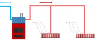
Installation diagram of air heaters in supply ventilation
Air supply units with an electric heater also ensure that fresh, clean, cool air enters the room. At the same time, waste materials exit through the ventilation system. Both in industry and in everyday life, air supply units with an electric heater operating from the network are more in demand.
Heat transfer coefficient of the heater
6. Calculation of the heat transfer coefficient (thermal efficiency) of the selected supply air heater. The heat transfer coefficient of the selected air heater can be found in two ways. The first is to calculate using the formula (using the coefficients and exponents of a given type of heater). The second is to use a ready-made table with data for different indicators of mass air speed and water speed. Tabular data can be viewed on the website page: KSk heaters. Heat transfer coefficient of heaters KSk.
| Calculation values for calculating heat transfer coefficients | |||||||||||
| KSk2 (2-row model) | A | n | m | KSk3 (3-row model) | A | n | m | KSk4 (4-row model) | A | n | m |
| 33.3 | 0.383 | 0.175 | 29.3 | 0.437 | 0.168 | 25.5 | 0.496 | 0.160 | |||
K W/(m²•°С) = A • Vⁿ • Wᵐ V – actual mass air velocity, kg/m²•s; W is the speed of water movement in the tubes, m/sec; A, n, m - the value of the module and degrees from the table.
An example of selection and calculation of a KSk air heater. Step-6
Select a suitable KSk heater for heating 16,000 m³/hour from a temperature of -25°C to +23°C. The coolant is hot water with a schedule of 95°C at the inlet to the air heater, 60°C at the outlet. 6. The task is to calculate the heat transfer coefficient of KSk air heaters number 11 at a mass velocity in the frontal section of 3.48 kg/m²•s and the corresponding speed of coolant movement in the tubes. K W/(m²•°C) = 33.3 • 3.480.383 • 1.2500.175 = 55.82 W/(m²•°C) - for the KSk air heater 2-11 K W/(m²•°C) = 29.3 • 3.480. 437 • 0.8300.168 = 48.97 W/(m²•°C) - for heater KSk 3-11 K W/(m²•°C) = 25.5 • 3.480.496 • 0.6250.160 = 43.91 W/(m²•°C ) — for air heater KSk 4-11 3.48 — actual mass air velocity, kg/m²•s; 1.250, 0.830, 0.625 - the speed of water movement in the tubes of two, three and four row heaters of the 11th number, respectively, m/sec; 33.3, 0.383, 0.175 (29.3, 0.437, 0.168; 25.5, 0.496, 0.160) - the value of the module and degrees from the table depending on the row of the air heater.
Temperature pressure of the heater
7. Calculation of temperature pressure. Below are formulas for determining the arithmetic mean or logarithmic mean temperature difference (depending on the final temperature delta ratio). If this step causes you difficulties, you can skip it and go to point 8. There is a general formula for finding the actual thermal power of the selected heater, which will allow (in most cases) to select a heat exchanger with an acceptable degree of error.
The operating principle of a water heater is based on the heat exchange of two media. The primary coolant is hot or superheated water, the secondary is air. Therefore, this heat exchanger is also called water-air heat exchanger. Heating of the air occurs due to the transfer of heat from the primary coolant (hot water) to the secondary coolant (cold air). That is, we can conditionally divide the heat exchange media into two flows or circuits. The first circuit is the heating side - hot water coolant, the second circuit is the heated side - air coolant. The greater the temperature difference between the flows, the more efficient the heat exchange occurs. The average temperature difference is calculated in the following sequence: Δt1=T1-T3 Δt2=T2-T4 T1 - inlet temperature (hot side); T2—outlet temperature (hot side); T3—outlet temperature (cold side); T4 - inlet temperature (cold side). Δt B - the largest value of the temperature deltas; Δt m is the smaller value of the temperature deltas.
The natural logarithm of ln is the logarithm of base e, where e is an irrational constant equal to approximately 2.71828. The designation is ln(x) exponent to which the number 2.71828 must be raised to get x.
An example of selection and calculation of a KSk air heater. Step-7
Select a suitable KSk heater for heating 16,000 m³/hour from a temperature of -25°C to +23°C. The coolant is hot water with a schedule of 95°C at the inlet to the air heater, 60°C at the outlet. 7. The task is to calculate the average temperature difference with the coolant at the inlet +95°C - at the outlet +60°C, the temperature of the inlet-outlet air -25°C - +23°C. Δt1=95-23=72 Δt2=60-(-25)=85 +95°С — inlet temperature (hot side); +60°С — outlet temperature (hot side); +23°C — outlet temperature (cold side); -25°C — inlet temperature (cold side). Δt B - the largest value of the temperature deltas = 85; Δt m - the smaller value of the temperature deltas = 72.
The average temperature pressure for heaters KSk2, KSk3 and KSk4 number 11, heating air from -25°C to +23°C with hot water with a schedule of +95°C-60°C is 78.5°C.
It should also be taken into account that when ΔtB / Δtm > 1.8, the formula is used to find the average logarithmic temperature difference. A detailed description of the calculation using this formula can be found on the website page: Selection of KPSk air heaters.
Actual heater power
8. Calculation of the actual thermal power of the selected heater(s) for supply ventilation. q (W) = K • F • ((t in + t out)/2 - (t start + t end)/2)) or, if the temperature difference is calculated, then q (W) = K • F • average temperature pressure K—heat transfer coefficient, W/(m²•°C); F - heating surface area of the selected heater (accepted according to the selection table), m²; tin—water temperature at the inlet to the heat exchanger, °C; tout—water temperature at the outlet of the heat exchanger, °C; t start — air temperature at the inlet to the heat exchanger, °C; t con is the temperature of the heated air at the outlet of the heat exchanger, °C.
An example of selection and calculation of a KSk air heater. Step-8
Select a suitable KSk heater for heating 16,000 m³/hour from a temperature of -25°C to +23°C. The coolant is hot water with a schedule of 95°C at the inlet to the air heater, 60°C at the outlet. 8. Calculation of the actual heating capacity of air heaters KSk number 11, with the specified and calculated values, is carried out using the following formula for calculating the heater power: q (W) = 55.82 • 57.1 • ((95 +60)/2 - (-25 +23) /2)) = 250205 W - for heater KSk 2-11 q (W) = 48.97 • 86.2 • ((95 +60)/2 - (-25 +23)/2)) = 331365 W - for heater KSk 3 -11 q (W) = 43.91 • 114.2 • ((95 +60)/2 - (-25 +23)/2)) = 393640 W - for heater KSk 4-11 55.82, 48.97, 43.91 - heat transfer coefficients of heaters, W/(m²•°C); 57.1, 86.2, 114.2 - heating surface area of air heaters, m²; 95 — water temperature at the inlet to the heat exchanger, °C; 60 — water temperature at the outlet of the heat exchanger, °C; -25 — air temperature at the inlet to the heat exchanger, °C; 23 — temperature of heated air at the outlet of the heat exchanger, °C.
Heat exchanger calculation method (surface area)
So, we have calculated parameters such as the amount of heat (Q) and the heat transfer coefficient (K). For the final calculation, you will additionally need the temperature difference (tav) and the heat transfer coefficient.
The final formula for calculating a plate heat exchanger (heat transfer surface area) looks like this:
In this formula:
- the values of Q and K are described above;
- the tav value (average temperature difference) is obtained by the formula (arithmetic mean or logarithmic mean);
- heat transfer coefficients are obtained in two ways: either using empirical formulas or through the Nusselt number (Nu) using similarity equations.
Actual water flow and speed
9. Calculate the actual flow and speed of the coolant. 9.1 Calculation of actual hot water consumption. gw (kg/sec) = q / (cw • (t in - t out)) q - actual thermal power of the selected air heaters, W; cw is the specific heat capacity of water (the water temperature at the supply and outlet is summed up and divided in half), J/(kg•°C); tin—water temperature at the inlet to the heat exchanger, °C; tout—water temperature at the outlet of the heat exchanger, °C. 9.2 Calculation of the actual coolant velocity. w (m/sec) = gw / (pw • fw) gw - actual coolant flow, kg/sec; pw—density of water at average temperature in the air heater, kg/m³; fw is the average open cross-sectional area of one pass of the selected heat exchanger, m².
An example of selection and calculation of a KSk air heater. Step-9
Select a suitable KSk heater for heating 16,000 m³/hour from a temperature of -25°C to +23°C. The coolant is hot water with a schedule of 95°C at the inlet to the air heater, 60°C at the outlet. 9. The task is to clarify the actual flow rate and speed of the coolant in the selected heat exchangers. 9.1 Calculation of actual hot water consumption gw (kg/sec) = 250205 / (4196 • (95 - 60)) = 1.704 kg/sec = 6134 kg/hour - for heater KSk 2-11 gw (kg/sec) = 331365 / (4196 • (95 - 60)) = 2.256 kg/sec = 8122 kg/hour - for heater KSk 3-11 gw (kg/sec) = 393640 / (4196 • (95 - 60)) = 2.680 kg/sec = 9648 kg/hour - for heater KSk 4-11 250205, 331365, 393640 - actual thermal power of two, three and four-row models, W; 4196—specific heat capacity of water at an average temperature of 77.5°C, J/(kg•°C); 95 — temperature at the inlet to the heat exchanger KSk, °C; 60 — temperature at the outlet of the heat exchanger, °C. 9.2 Calculation of the actual coolant speed w (m/sec) = 1.704 / (973 • 0.00156) = 1.123 m/sec - for the KSk 2-11 air heater w (m/sec) = 2.256 / (973 • 0.00235) = 0.987 m/sec - for heater KSk 3-11 w (m/sec) = 2.680 / (973 • 0.00312) = 0.883 m/sec - for heater KSk 4-11 1.704, 2.256, 2.680 - actual coolant consumption by heaters, kg/sec; 973 - density of water at average temperature in the heat exchanger, kg/m³; 0.00156, 0.00235, 0.00312 - average open cross-sectional area of one pass of heaters KSk2-11, KSk3-11, KSk4-11, respectively, m².
Heater power reserve
10. Determine the thermal performance reserve of the adopted heater(s). ((q - Q) / Q) • 100 q - actual thermal power of the selected air heaters, W; Q is the calculated thermal power for heating the required volume of air, W. The actual thermal performance of the adopted ventilation heater must be greater than the calculated one. The range of the permissible percentage ratio of actual and calculated power, according to various sources, can be from 96 to 120 (from - 4 to 20)%. In any case, you need to strive for the closest possible equality of power (actual performance = 100 - 110% of the calculated one). If, during the calculation, the difference is greater than the above figures, a recalculation should be made.
An example of selection and calculation of a KSk air heater. Step-10
Select a suitable KSk heater for heating 16,000 m³/hour from a temperature of -25°C to +23°C. The coolant is hot water with a schedule of 95°C at the inlet to the air heater, 60°C at the outlet. 10. We calculate the discrepancy between the actual and calculated thermal power of the selected heat exchangers ((250205 - 278720) / 278720) • 100 = -10.2% - for the KSk 2-11 air heater ((331365 - 278720) / 278720) • 100 = 18.9% - for heater KSk 3-11 ((393640 - 278720) / 278720) • 100 = 41.2% - for heater KSk 4-11 250205, 331365, 393640 - actual thermal power of selected water heat exchangers, W; 278720 — calculated thermal power for heating a given volume of air, W. Of the considered models of heaters KSk number 11, only the three-row air heater KSk 3-11 corresponds, under given conditions, to the recommended ratio of actual and calculated power.
The need to calculate the heater
Equipment for air heating of premises requires proper selection. Matching the power and performance of the devices to the parameters of the building, climatic conditions or the needs of people are the most important aspects of the operation of air heaters. If the installed device does not meet the needs of the premises and does not cope with its functions, then a feeling of discomfort will appear, the performance of personnel will decrease, and production conditions will worsen, which may negatively affect the quality of products, services provided, or other areas of human activity.
READ MORE: Plastic insert in the well: step-by-step installation instructions
Expert opinionHeat supply and ventilation engineer RSV Fedorov Maxim Olegovich
Important! It should immediately be noted that performing such a calculation is a complex task that requires considerable experience and knowledge. For an unprepared person, such a task will most likely be overwhelming and will require turning to specialists
If you don’t have confidence in your abilities, then it’s better not to waste time and immediately order a calculation from a specialized organization that employs competent specialists.
Selecting a device type
Before you start choosing the type of device, you need to find out what kind of air heaters exist. They can be:
- electric
- water
- gas
Heater air resistance
11. Calculation of aerodynamic drag. The amount of air losses can be determined in two ways. The first is to calculate using a formula using the coefficient and degree values of the selected heater. The second is by selection - according to the table, using data at different mass air speeds. View the table with data on the aerodynamic resistance of KSk water heaters.
| Estimated values for calculating aerodynamic drag | ||||||||
| KSk2 (2-row model) | B | r | KSk3 (3-row model) | B | r | KSk4 (4-row model) | B | r |
| 4.23 | 1.832 | 6.05 | 1.832 | 8.63 | 1.833 | |||
ΔPa (Pa) = B • Vʳ V – actual mass air velocity, kg/m²•s; B, r - the value of the module and degrees from the table.
An example of selection and calculation of a KSk air heater. Step-11
Select a suitable KSk heater for heating 16,000 m³/hour from a temperature of -25°C to +23°C. The coolant is hot water with a schedule of 95°C at the inlet to the air heater, 60°C at the outlet. 11. The task is to find out the aerodynamic resistance of the selected air heaters when working under given conditions. ΔPa (Pa) = 4.23 • 3.481.832 = 41.5 Pa - for heater KSk 2-11 ΔPa (Pa) = 6.05 • 3.481.832 = 59.4 Pa - for heater KSk 3-11 ΔPa (Pa) = 8.63 • 3.481.833 = 84.9 Pa - for heater KSk 4-11 3.48 - actual mass air velocity in the frontal section, kg/m²•s; 4.23, 1.832 (6.05, 1.832; 8.63, 1.833) - the value of the module and degree from the table depending on the row of the air heater.
When installing water heaters sequentially along the direction of air movement, we multiply the resulting aerodynamic resistance value by the number of rows of supply ventilation heat exchangers.
The principle of calculation when selecting a PES with a recuperator
In both cases, approximately the same calculations await us. At the “head of the table” is performance or air flow. Productivity is the amount of air passed per unit of time. Measured in cubic meters. m/hour. To select this indicator, we calculate the volume of air in the ventilated rooms and add 20% (for the resistance of filters and grilles). The resistance of the built-in recuperator is already taken into account in the installation data sheet.
Attention! When making your own calculations, rounding and tolerances should be made with an increase towards the margin (power, productivity, volume). Let's consider the example of a country house with ceilings of 2.4 m, served by 2 bedrooms (12 m2 each), a living room (20 m2), a bathroom (6 m2) and a kitchen (12 m2)
Let's consider the example of a country house with ceilings of 2.4 m, 2 bedrooms (12 m2 each), a living room (20 m2), a bathroom (6 m2) and a kitchen (12 m2).
Total air volume: (2 x 12 + 20 + 6 + 12) x 2.4 = 148.8
, we take 150 m 3.
Note.
The choice of a more powerful installation is justified if it is possible to increase the area of the premises and to increase the resource of the unit.
Air handling units with built-in recuperators
| Index | PVU model | |||||
| VUT 200 G mini | VUT 400 EG EC ECO | Dantex DV-350E | DAIKIN VAM350FA | |||
| , Ukraine | VENTS, Ukraine | VENTS, Ukraine | Dantex, England | Daikin, Japan | Daitherm, Denmark | |
| Productivity, m 3 /hour | 100 | 200 | 450 | 350 | 350 | 520 |
| 86 | 116 | 300 | 140 | 200 | 350 | |
| Recuperator type | Plates, paper | Plates, aluminum | Counterflow, polystyrene | Counterflow, polymer | Counterflow, aluminum | Plates, bimetal |
| 68 | 85 | 98 | 88 | 92 | 95 | |
| Note | Coarse filters | G4 filters, heating optional | Filters G4, F7, heater | 3 operating modes, filters | Fully automatic, replaceable filters | Fully automatic, room version |
| price, rub. | 13800 | 16500 | 20800 | 32200 | 61700 | 85600 |
For those who fundamentally do everything themselves, calculations of system performance will concern fans built into the ducts. Their performance should already be calculated when designing (calculating) channels depending on the air volume. To select the appropriate recuperator, we calculate the total performance of the fans operating for inflow to the heat exchanger and subtract 25% (for system resistance, variable cross-section and synchronous operation). One duct fan must also be installed at each inlet and outlet of the recuperator.
For our example:
Factory heat exchangers
Question
: What do the numbers 40-20 mean in the labeling of factory recuperators?
Answer:
Dimensions of inlet and outlet channels in millimeters. 40-20 are the minimum dimensions of factory heat exchangers.
When installing such a device in a cold place, for example, in the attic, remember that it and the air ducts should be insulated.
Another type of recuperator is autonomous channel heat exchangers. They are also called ventilators. These devices serve only one room and belong to the so-called decentralized ventilation system. They do not require calculations; it is enough to select a model for the volume of the room.
Air ventilators
| Index | Duct ventilator model | ||||
| PRANA-150 | VENTS TWINFRESH R-50/RA-50 | O'ERRE TEMPERO | MARLEY MENV 180 | SIEGENIA AEROLIFE | |
| Manufacturer | Ukraine | Ukraine | Italy | Germany | Germany |
| Productivity, m 3 /hour | up to 125 | 60 | 62 | 68 | 45 |
| Energy consumption (without heater), W | 7-32 | 3-12 | 12-32 | 3,5-18 | 8,5 |
| Recuperator type | Plates, polymer | Plates, bimetal | Channel, aluminum | Plates, bimetal | Channel, bimetal |
| Recovery efficiency, up to % | 67 | 58 | 65 | 70 | 55 |
| Note | Remote control, “winter start” | 4 modes, 2 filters | 32 dB, 5 modes | 40 dB, G4 filters | Synth. filter, 54 dB |
| price, rub. | 9 300 | 10200 | 14000 | 24500 | 43200 |
Vitaly Dolbinov, rmnt.ru
Water heater resistance
12. Calculation of the hydraulic resistance of the selected heater(s) of the supply ventilation units. Coolant resistance is calculated using formulas. The first requires a fairly large number of actions and is described in detail on the website page: KSk heaters. Hydraulic resistance of heaters KSk. The second is simpler and is solved on the basis of already calculated hydraulic resistance coefficients for specific models of KSk air heaters. The table with odds is presented on the above page. In the same table, focusing on the speed of water in the tubes and the mass speed of air in the frontal section, you can find out the value of water resistance without resorting to calculations. ΔPw (kPa) = C • W² C – the value of the hydraulic resistance coefficient of a given heat exchanger model (see the table); W is the speed of water movement in the tubes of the air heater, m/sec.
An example of selection and calculation of a KSk air heater. Step-12
Select a suitable KSk heater for heating 16,000 m³/hour from a temperature of -25°C to +23°C. The coolant is hot water with a schedule of 95°C at the inlet to the air heater, 60°C at the outlet. 12. The task is to find out the hydraulic resistance of the selected heater when working with the given conditions. ΔPw (kPa) = 21.99 • 1.123² = 27.73 kPa - for heater KSk 2-11 ΔPw (kPa) = 34.25 • 0.987² = 33.37 kPa - for heater KSk 3-11 ΔPw (kPa) = 37.15 • 0.883² = 2 8.97 kPa - for heater KSk 4-11 21.99, 34.25, 37.15 - the value of the hydraulic resistance coefficients for heaters KSk2-11, KSk3-11, KSk4-11 (taken from the table); 1.123, 0.987, 0.883 - speed of water movement in the tubes of the adopted air heaters, m/sec.
If two or more heaters are taken into account for the calculation and they are connected in series through the coolant, the resulting value of hydraulic resistance is multiplied by the number of heat exchangers connected in series through water.
Advantages and disadvantages
Despite all their convenience, heaters consume a large amount of electricity.
Water and steam heaters designed for heating industrial premises are extremely profitable because they do not require additional investments. Financial resources are spent only on the purchase of the device. Their advantages:
- quickly achieving the desired air temperature;
- simple installation;
- safety;
- reliability;
- possibility of adjusting the heating level.
Disadvantages include:
- use in rooms with positive air temperatures;
- impossibility of using for heating apartments;
- equipment is required to provide air traction;
- If the coolant supply stops, the system stops working.
The last point is also true for electric heaters, but only concerns power outages.
Selection of heater
13. Final indicators of calculation and selection of air heaters KSk 02 HL3 (TU 4863-002-55613706-02) produced by T.S.T. LLC. As a result of the calculation and selection of a heater for heating incoming air from -25°C to 23°C with a volume of 16,000 m³/hour, using a coolant - hot water with a temperature curve of 95°C - 60°C, a finned water heat exchanger KSk 3- was selected 11 three-row, four-way. Data obtained: 1. heater heat power - 331 kW; 2. mass velocity in the frontal section - 3.48 kg/m²•s; 3. coolant consumption - 8122 kg/hour; 4. speed of hot water in the heat exchanger - 0.99 m/sec; 5. thermal power reserve - 19%; 6. aerodynamic resistance - 60 Pa; 7. hydraulic resistance - 33 kPa.
Go to page: Heaters KSk. Production, technical characteristics. The page contains drawings, photographs, descriptions and calculations of these air heaters, tables with thermal characteristics, overall dimensions of water finned heat exchangers of the KSk-02-HL3 type.