Pipe selection
The main point of installing collector wiring is the correct choice of pipes. In the installation of this system, a large number of connections are used, which entails the use of a large number of clamps and fittings. For this purpose, soft, flexible suture metal-plastic or polyethylene pipes are most suitable. Copper pipes are used to exit the pipes from the manifold.
These pipes have the properties of preventing air from entering due to a special coating on the outer surface.
The most optimal pipe diameter is 16 mm. However, you should consult a specialist on this issue.
Selecting pipes for a heating system for a residential building or apartment
When creating a manifold wiring diagram for heating a low-rise residential building or other private building, it is necessary to take into account the method of laying pipes throughout the house. If the piping will run under the floor, in a concrete screed, then it is recommended to buy heating pipes in coils so as not to make connections in the floor, as mentioned above.
Plastic pipes must have sufficient flexibility, the pipe material must not be subject to corrosion and the influence of aggressive environments, must not be destroyed at low or too high temperatures, and the service life of the pipes must be extremely high.
The requirements for temperature resistance and tensile strength of pipes are determined by the performance characteristics of the installed heating system in a house or apartment. For individual development, the pressure in the pipes should not exceed 1.5 atm, and the maximum temperature regime should be in the range of 50C -75C. If the house has a “warm floor” system, then the temperature of the coolant in the pipes should not rise above 30C -40C.
Manifold for combined heating
When installing a manifold circuit, the pressure in the pipes will always be high, and the pipe material must withstand ≥ 10-15 atm. at a coolant temperature of up to 110-120C. Therefore, when laying heating pipes in an apartment building, it is recommended to use corrugated pipes made of stainless steel, rather than metal-plastic or PVC products. As a working example, we can cite the Kofulso brand of pipes, which can withstand pressures of more than 15 atm. at coolant temperature ≥ 110C. The pressure force that causes the destruction of this material is 215 kgf/cm², which is an excellent indicator.
Collector wiring in the apartment
The bending radius of such stainless pipes is equal to their diameter, which allows them to be laid in almost any place and with any bend, without fear that the pipe will leak at the bend. Connections in such piping are made using special fittings, and the twist points are fixed with a lock nut, which ensures the tightness of the connection of corrugated pipes with silicone seals.
But stainless steel is not the cheapest material, and when installing manifold pipes in a two- or three-story building, such a project will be quite expensive. Therefore, it makes sense to use, for example, PE-X brands. These pipes, like other PVC products, are sold in coils, the length of one pipe is 200 meters, the material is able to withstand pressure up to 10 kgf/cm² at a coolant temperature in the system up to 95C. A short-term increase in temperature up to 110C is allowed.
Corrugated stainless steel pipes
Water pipes made of cross-linked polyethylene are also connected to each other using special fittings in the form of plastic or metal (bronze, brass, copper) fittings with a locking ring, which fits tightly onto the pipe and seals it tightly. The advantage of such pipes is that cross-linked polyethylene has a mechanical memory, that is, assembly is carried out according to the following scheme: the pipe is stretched with a special extender so that a fitting can be inserted, and after some time (up to a minute) the pipe takes on the original diameter and tightly presses the fitting. Additionally, tightness is ensured by a locking ring.
In what cases is a collector heating system acceptable?
There is no standard solution when drawing up a diagram of a collector system, and there are also no generally accepted planning standards. The selection of equipment should be carried out by specialists, taking into account the specific tasks that need to be solved.
The opinion of experts should not be ignored: such a system cannot be recommended for heating in multi-storey buildings.
Heating system options in multi-storey buildings
The problem is that heating in the apartment is provided by the supply of coolant to at least two risers. A prerequisite for the system under consideration is the connection of all radiators to one riser.
Having left one source of heat, you will need to shut off the others, i.e. brew them. The entire load will be concentrated on the left riser, and a closed hydraulic circuit will be formed within a particular apartment.
All radiators located on the upper floors will be cut off from the centralized heating system and no coolant will flow into them. Naturally, residents of the upper floors will express dissatisfaction and will demand the forced restoration of the previous communications.
The only legal option for using collector circuits in an apartment building would be when additional valves were installed during the construction process, allowing the connection of circuits of different configurations.
Selecting a distribution manifold
Using a distribution manifold is convenient and practical and has a number of advantages. To choose the right distribution manifold, you need to know in advance which heating devices will be connected to it; this determines what additional devices you will need and the type of manifold itself.
It is better to choose manufacturers who have proven themselves in the market, study customer reviews of the products, and consult with several sellers on the topic of the same collector.
Whatever your capabilities, you must remember that the price of a high-quality distribution manifold and its components cannot be low.
Specifics of distributor operation
Collector design
The collector is a distribution-type device for a heating system, which promotes uniform heat distribution. The cooled water flows back into the boiler under the influence of circulation. The main branches attached to the distributor function independently.
Device design
The intermediate node consists of two parts. The supply comb supplies the coolant to the communications, and the return comb leads it to the heat generator when it cools. Two combs are a collector group, and each of them can connect one circuit or several connections to heating devices. The pressure inside each circuit is adjustable.
Features of work
The principle of operation of collector heating is to heat the water with a heat generator and send it to the supply comb. Due to the large internal diameter of the unit, the liquid contained in it slows down the speed and is distributed over all outlets.
The coolant moves to the individual circuit through connecting pipes with a smaller diameter than the distributor. Heated water can be directed to radiators and underfloor heating systems, ensuring uniform heating of each element.
After entering the circuit and releasing heat, the water moves through another pipeline to the distributor. The direction will be the opposite. Having reached the return comb, the coolant is sent to the heat generator.
Components of a manifold heating system
The configuration of a collector heating system is similar in its composition to a two-pipe (tee) system. The main, most expensive component is the boiler. The energy efficiency of the system depends on its effectiveness. The boiler power depends on the heated area and heat loss. In this regard, choosing a boiler and calculating its efficiency is a fairly serious part of the design, requiring consultation with a specialist.
In the background, they rightfully consider the level of heat transfer of the system, for which the radiators are responsible. But we should also not forget about possible heat loss. To minimize them, it is worth thinking about high-quality insulation of the house.
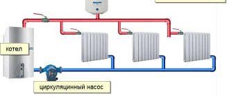
The manifold wiring of heating systems provides for a built-in pump for circulating coolant. The pump increases the heat transfer of the system, allowing the coolant to circulate as quickly as possible.
An important element of the system is the collector. The collector serves as a coolant distributor, facilitating efficient water supply. The collector consists of various regulators, valves, and temperature sensors that allow you to regulate the room temperature.
Types of collectors
Manifold for radiator heating
The collector is designed for a closed circulation heating system. The device comes in several modifications.
Radiator manifolds
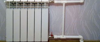
The water device is placed on the battery and promotes uniform distribution of water in each section. It can be connected at the top, side, bottom or inserted diagonally. If you have an apartment, a bottom installation would be optimal - the contours are hidden under the baseboard or floor covering.
A private house is equipped with radiator distributors on each floor. They are placed in the center of the wiring, hidden in niches or special cabinets. If the same number of rings is not supplied to the collector devices, an individual circulation pump is used for each outlet.
The radiator type of mechanisms has several connection features:
- branches of the distribution unit form separate circuits with shut-off valves;
- for heated floors, copper or polypropylene pipes are used;
- the connection is made using one-piece fittings;
- valves are installed to regulate the amount of coolant;
- the circulation sediment is located in the intermediate unit at the entrance to the return pipe;
- the number of pipes depends on the number of rooms connected to one comb.
Thermohydraulic distributor
Gidrostrelka
Gidrostrelka is used in a productive or branched heat supply system to which multi-storey buildings are connected. On one side of the link-link there is a circuit for a heating boiler, on the second - heating radiators or heated floors.
The distribution hydraulic manifold provides:
- elimination of sudden changes in water temperature;
- increasing operational resources in the system;
- saving fuel and electricity;
- maintaining a constant volume of water in the reservoir through mixing and secondary circulation;
- compensation of secondary circuit coolant costs;
- separation of the boiler hydraulic circuit from the secondary wiring;
- maintaining the temperature balance of heating communications.
Solar collector devices
Solar collector diagram
In regions without autonomous water supply or non-gasified areas, heating can be realized using solar collectors. Structurally, the devices are designed like greenhouses capable of accumulating solar energy. The coolant circulates naturally - circulation flows are created by fans of the absorber plate.
The sun's rays are received by a distributor in the form of a flat box. The black heat-receiving plate accumulates heat flows and transfers them to the heat carrier, which uses air flow or water. Innovative systems work in the direction of the sun's movement.
Solar installations are expensive, and even in the southern regions they are used as an auxiliary heating device.
Installation of a collector heating system
It is advisable to install a collector heating system during the pre-finishing period.
With a horizontal type of heating distribution, a special closed box is installed for the distribution manifold, pump and equipment for adjusting parameters.
It is better to place the collector box in a place where there is no humidity. Usually, a niche in the corridor, a dressing room, a storage room, as well as a specially designated space for communications - a boiler room - are used as the location of the box.
In a building consisting of two floors, collectors with associated equipment are installed on all floors.
Each collector has a certain number of inlet and outlet openings, exactly as many as heating devices - radiators or heated floor coils.
In all rooms, separate branches are laid, combining several heating devices; with this connection, two radiators from the same room for the collector will represent a single heating device.
To organize a heated floor, a collector heating system with wiring in the floor is used. However, not only the installation of heated floors involves laying pipes from below.
Most often, a collector heating system involves placing heating lines under concrete; the height of the screed should vary from 5 cm to 8 cm. Only solid lines are placed in concrete, mostly metal-plastic pipes with a diameter of 1.6 cm. Such pipes are quite flexible, they can be easily lay under concrete.
It is worth remembering that before pouring concrete, a layer of thermal insulation is laid on the pipes and this is done in order to prevent contact between the concrete and the pipes.
A layer of thermal insulation between the lines and concrete will extend the life of the pipes. Sheets of plywood are placed on top of the screed, and the floor covering is already on them.
The lines can be connected to the radiators either from above or from below, that is, the manifold wiring of the heating system can be top or bottom.
Installation of distribution comb
On the floors of houses with horizontal heating distribution, to accommodate the collector, circulation pump and control equipment, you will need to install a closed box - a collector cabinet.
A closed box will protect equipment and shut-off valves from external mechanical influence and give the room a more aesthetic appearance
The manifold cabinet is installed in separate niches of rooms protected from moisture. Most often, a place is allocated for this in the hallway, dressing room or pantry.
When designing the heating of a two-story building, it will be necessary to install two collector groups: on the first and second levels. Additional distribution units will ensure approximately the same length of the circuit.
As an option, you can take as a basis a scheme in which the first group will be responsible for the distribution of heat along individual circuits, and the second will act as a key component in arranging a “warm” floor.
The heated coolant from the room with the boiler flows through the main lines to the collectors installed floor-by-floor
The number of collector inputs and outputs is always equal to the number of heating elements located on the floor: radiators or underfloor heating rings. For each room, a separate branch is laid, which, by combining several heating devices, will implement a passing or dead-end circuit.
To reduce the cost of connecting radiators, a “pass-through” circuit is used.
In a “pass-through” scheme, the thermal valve is installed only on the first circuit of the radiator; due to which the water flow is regulated on all devices connected in series behind it
With a “pass-through” system, several devices connected in series will be perceived as one element.
Disadvantages and advantages of the collector circuit
The complexity of piping when implementing a collector circuit is compensated by its advantages:
Each radiator is an autonomous and separately controlled element
That is, in each room you can set the desired temperature regardless of the temperature in the boiler or in other heating circuits, or turn off the radiator (group of radiators) without stopping the heating system; Taking into account the fact that each heat pipe connected to the manifold from the heating system transports hot liquid to only one heating device, it is more advisable to use pipes of reduced diameter compared to the calculated total diameter of the pipes. In this case, it is recommended to maintain the minimum permissible distance between the heating device or group of radiators and the collector.
Separate connection of heating devices
A homemade or factory-made collector heating system, the diagram of which for general cases is given above, is valued by consumers due to the possibility of creating several independent heating circuits with different temperatures and pressures. This scheme allows you to organize different temperature conditions for different rooms in the same building with one boiler. To connect several circuits, another version of the collector is equipped - a hydraulic arrow, which outwardly looks like a large water pipe.
The hydraulic arrow is installed differently from the manifold - the circulation cycle is closed between the coolant supply pipe and the return pipe. The boiler continues to continuously heat the liquid in the primary circuit, and the coolant in the hydraulic arrow begins to move, allowing it to be cut into to connect radiators at different points and at different levels.
Due to this unusual connection of radiators to the hydraulic arrow, at the end point of a single heat sink (radiator) there will be different temperature and pressure indicators. Turning on the hydraulic arrow is advisable when combining the distribution of heating pipes using radiators and a “warm floor” system.
Homemade hydraulic gun
At the places where the circuits are connected, the pressure and temperature in the pipes will be different, but if the collector and the drawings of which were developed for circulation pumps will use them, then this difference in drops does not matter. Also, heating circuits can be connected in series (no more than two in a circuit), but with this arrangement of connecting the circuits it will be impossible to regulate separately from each other.
Series connection of collectors
The disadvantages of the collector organization of piping should be noted as follows:
- The energy consumption of the collector circuit is higher than when batteries are connected in series. Moreover, the larger the heated area, the higher the heat costs;
- Manifold heating equipment is designed to operate only in a one- or two-pipe heating system design, which can be routed along the walls of the premises. But when organizing radial distribution, it will not be possible to lay pipes along the walls or in a hidden way due to the large volume of the practical circuit and the large number of heating pipes;
- When laying pipes in the floor under a concrete screed, the following disadvantages of the method appear: for pipes laid under the floor, it is not allowed to make any connections - neither welded, nor threaded, nor any other, in order to prevent hidden leakage, otherwise the layer will have to be removed concrete screed, and this is almost a major renovation of the premises with all the ensuing consequences;
- The total hydraulic resistance of the collector heating circuit will be significant, especially when laying pipes with a small diameter. Also, when implementing a collector pipe routing scheme, it is necessary to use a circulation pump (pumps), since the natural pressure in the pipes will not allow the coolant to move freely through the pipes;
- When using several autonomous heating circuits in a collector heating circuit, each large circuit must have its own circulation pump installed. This leads to financial costs both during installation of the system and during its operation;
- The energy dependence of the collector heating system is one of its significant disadvantages, since circulation pumps require connection to the electrical network. In the event of an emergency power outage, the heating will not be able to provide the required thermal conditions, since the movement of the coolant through the pipeline will simply stop.
Advantages of a collector circuit
This scheme allows you to regulate the amount of heat supplied to each consumer, as well as turn off individual heating devices if there is temporarily no need to heat part of the premises.
Combs mounted on common brackets.
If a leak occurs in one of the circuits of the radiant heating system, it can be turned off while the malfunction is being eliminated without stopping the operation of the rest of the system. Also, the ability to turn off one of the circuits is used when replacing heating devices.
Photo of the collector comb.
Heating of a private house, made using a collector circuit, has a more aesthetic appearance than systems of other types. This is achieved due to the fact that the heating pipelines are located under the floor surface. Due to the relatively short length of the collector system contours, it is possible to use pipes of smaller diameter compared to one- and two-pipe heating, which allows the height of the poured floor to be somewhat reduced.
Only a collector heating circuit makes it possible to install underfloor heating systems. This heating scheme allows you to equip some rooms of the house with radiators or convectors, and install heated floors in others.
Mixing unit equipment
Listed above are the main components that you will need to assemble the mixing unit yourself. We will describe the completeness in more detail in the table below.
In addition to the above, other parts of pipeline installation can be used to assemble the mixing unit, such as couplings, American ones, and others. They need to be determined at the location where the mixer is installed. Materials need to be used to seal joints.
As a result of the work on assembling mixers, a control panel for the heating system, called a manifold, is obtained.
Heating system manifold for a private house
It can be quite complex or completely simple, located in the basement or in living quarters in specially made manifold cabinets. The main thing is accessibility for maintenance and repair.
Video: how to assemble a mixing unit with your own hands
Knowing from this article how the parts and devices of the mixing unit interact, the developer, even with minimal plumbing skills, will cope with the assembly task. Carefully install one circuit, the rest will roll like clockwork. I wish you success!
How I installed the collector wiring with my own hands.
1.
I decided to install a gas floor-standing boiler in the basement of my house.
The boiler was installed on a concrete screed five centimeters thick.
2.
For the installation of the main pipelines I used a metal pipe with a diameter of 32 mm.
3.
A closed expansion tank was installed on the supply pipe.
4.
A circulation pump was installed on the return pipe.
Installing taps on both sides of the pump will allow you to change the device without draining the coolant.
Creating forced circulation in the heating system is mandatory. Forced circulation improves the efficiency of heating the coolant, and also simplifies the system and makes it more compact.
5.
We install collectors (distribution “combs”) on the main pipelines.
The combs are positioned so that the lengths to each heating device on the floor are approximately equal.
For example, if the distance from the collector to one radiator is 10 times greater than to the other, then the coolant pressure drop on the extended segment will be much higher than on the short one. The system is doomed to imbalance.
However, a difference of 2 times is not considered unacceptable.
6.
Each collector outlet has its own shut-off valve - a ball valve.
This allows, if necessary, to disconnect any radiator from the entire system without in any way affecting the operation of other heating devices. Each circuit is essentially an independent heating system.
It’s very convenient – I couldn’t be more pleased!
7.
I secured both collectors to a vertically placed metal corner.
8.
The wiring to the rooms was mounted along the basement ceiling using a metal pipe with a diameter of 15 mm.
9.
The rays of the circuits were connected to the collectors with a metal-plastic pipe.
10.
I installed a tap on the return pipe, through which I recharge the entire system.
11.
I punched holes in the floor slabs through which the pipes are connected directly to the heating devices.
12.
He connected the heating radiators to the risers of the circuits with a metal-plastic pipe.
This is my second winter using heating with manifold wiring. The system did not cause any serious failures, but we had to “fight” the formation of air in the system. There will be a separate article about this.
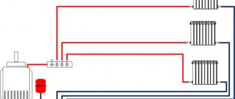
Collector heating system for a private house
Collector heating system for a private house. The main difference between such a heating system and other two-pipe varieties is the presence of a connecting unit that is connected directly to the boiler through two lines (supply and return) and distributes the coolant through small separate circuits.
The latter, in turn, are water underfloor heating pipes or supply lines and return collection from radiators. Each collector outlet is equipped with separate shut-off valves with continuously adjustable caps; the circuits are independent of each other and are easily disconnected and controlled.
The movement of water through numerous circuits is ensured by an electric circulation pump, usually located in the return line (an alternative is to install forced circulation devices at the beginning or at the return of each autonomous branch).
Stability and safety of operation is achieved by introducing a membrane expansion tank into the circuit, installed on a section of pipe with cooled coolant.
The minimum tank capacity must exceed the circulation volume by at least 3%, preferably more.
Additional security and control functions are provided by:
• Flow meters with transparent housings and indicators of the volume of passing coolant. These elements are optional and are installed in the supply manifold branches to improve control of water circulation in systems with complex configurations. • Thermostats placed at the entrance to manifold groups for the purpose of monitoring and adjusting the upper limit of water or antifreeze temperature. • Digital temperature sensors installed with similar tasks and supporting optimal heat transfer mode with a difference at the inlet and outlet to the collector of about 10 °C. • Bypasses – jumpers for mixing cooled coolant into hot water at the inlet. • Built-in air vents and separate air release mechanisms.
The number of circuits supported by a standard manifold depends on the parameters of the comb connector and varies from 2 to 12. In complex systems, manifolds with a large number of connectors can be installed, but this is usually not necessary.
The pipe material is selected based on the parameters of the coolant and the type of system (floor-mounted, radiator or combined); taking into account the likely hiding in the screed, preference is given to high-quality metal-plastic or cross-linked polyethylene.
Advice! No matter what anyone says, install pipes in a screed without joints, only in solid sections. It is important!
Advantages and disadvantages
The advantages of the collector circuit are manifested in:
• Increasing the overall efficiency of the system due to the accelerated supply of heated water or antifreeze to the heat exchangers, the possibility of reducing the cross-section of pipes (and, as a result, boiler performance) and reducing the proportion of heat loss. • Aesthetics. Reducing the diameter of the pipes makes it possible to hide them in a relatively thin floor screed. The comb assembly itself is located in a compact and inconspicuous box, often mounted in a niche. • Ability to control temperature and turn off circuits in individual rooms without reducing the performance of the entire system. • Relatively simple design and installation rules, the possibility of combining floor and radiator heating systems.
The main disadvantage of collector systems is considered to be high cost; installation of independent circuits (longer even in comparison with conventional two-pipe distributions) and distribution combs takes a lot of money and time. Such systems always depend on the operation of circulation pumps and are energy dependent.
In regions with frozen soil and frequent power outages, antifreeze replaces the water in the pipes, which also increases the cost.
As a result, collector systems are recognized as optimal for heating large-area private houses (including two-story ones) with different residential areas.
This type is recommended to be chosen if there are increased requirements for the aesthetics and energy efficiency of the system and to be installed at the stages of major construction or home renovation. Installation of manifold circuits and cabinets in the presence of previously laid and already used floors is considered labor-intensive and unjustified; in the absence of the possibility of hiding pipes in the screed, the wiring attracts undue attention and looks worse.
Advice! If you do the wiring outside of the screed, you can hide the pipes in boxes or behind drywall.
We manufacture a distribution manifold
We calculate the material required for the manufacture of the collector. The easiest way to do this is in Excel spreadsheets. At the same time, in this program you can calculate the cost of materials required for the manufacture of the device. We purchase the necessary starting material and prepare tools for self-production.
preparing tools
The starting materials for the main parts of the collector will be regular or square pipes. We make the necessary markings on them using calipers, a ruler and a core.
We make the necessary markings
Using a gas cutter, we make holes for the pipes.
make holes for pipes
We insert the pipes (pipe sections with threads) into the seats.
Insert the pipes
We fix the pipes by welding. First, rough it out, and then scald it around the entire perimeter.
We fix the pipes by welding
We also weld brackets to the body for wall mounting.
We weld the brackets to the body
We clean the welding areas from scale and rust.
Cleaning the weld areas
We treat the entire structure with a degreasing compound and cover it with paint and varnish.
treated with a degreasing compound, coated with paint and varnish
The paint completely sets in two to three days and we have a self-made distribution manifold at our disposal. Now all that remains is to install it in place and connect all the incoming and outgoing circuits to it.
ready-made homemade distribution manifold
A system with a distribution manifold will work much more efficiently than a simple pile of heating pipes
In order to catch all the nuances of making a distribution manifold yourself and the scope of its application, we recommend that you watch the training video.
Making a solar collector for alternative heating in your home
Recently, the interest of ordinary people in renewable energy sources has increased.
Because of this, many homeowners are looking to buy a solar collector for home heating, which converts the sun's energy to heat water. But the decision to buy a solar collector for heating in a store is not always rational. The cost of the finished device is far from budget, so such a purchase can hit the family budget hard. To avoid expenses, you can make a solar vacuum collector for heating yourself. Various solar collectors for home heating, reviews of which are positive, have the following design details:
- container for storing heated water;
- heat exchanger;
- device for collecting solar energy;
- insulating layer.
The materials from which the collector can be made are very diverse.
There are known technologies for the independent production of solar collectors from polypropylene, ordinary garden hoses, window frames, plastic bottles, old refrigeration units and other available materials. The collector assembly diagram directly depends on the type of material chosen, so it is worth studying after the owner has decided on the concept of the collector. Self-made vacuum solar collectors for home heating, the price of which in the store is $200 or more, can be used as full-fledged heating sources.
Vacuum solar collectors have a number of advantages:
- energy efficiency;
- environmental friendliness;
- autonomy;
- availability.
It is not difficult to make traditional distribution or solar collectors for heating your home with your own hands. This does not require large material costs, complex technological equipment or solid experience. However, these hand-made devices will greatly optimize the home heating system and will help the owner create a reliable, efficient and uniform source of heating for his home.
- How to fill water into an open and closed heating system?
- Popular floor-standing gas boiler made in Russia
- How to properly bleed air from a heating radiator?
- Expansion tank for closed heating: device and principle of operation
- Gas double-circuit wall-mounted boiler Navien: error codes for malfunctions
Recommended reading
Heating thermostat - operating principle of different types How to make an expansion tank for heating with your own hands? Bypass in a heating system - what is it and why is it necessary? Expansion tank for closed heating: device and principle of operation
2016–2017 — Leading heating portal. All rights reserved and protected by law
Copying site materials is prohibited. Any copyright infringement will result in legal liability. Contacts
Purpose of the heating manifold
The absence of a distribution manifold in a water heating system can lead to the fact that water may flow unevenly into different circuits of the system. As a result, you will have a hot floor and cold radiators, or vice versa.
This may occur because several heating system circuits can be connected to one boiler outlet. The liquid flows unevenly through such connections, as a result of which part of the premises will not have enough heat. But the efficiency of the heat supply system depends on the amount of coolant passing through the pipes, the volume and speed of its movement.
pipes coming from the boiler
Some home owners try to solve this problem by installing additional pumps and control valves. But this only complicates the system and does not always lead to uniform distribution of the coolant.
How is the coolant distributed in a private house?
Let’s take, for example, a heating system for a private house with an area of 100 square meters. The device for heating water will be a wall-mounted gas boiler with one outlet pipe with a diameter of ¾ inches.
In our house we have two heating circuits and one circuit that heats water for domestic use with indirect heating. All circuits are built from pipes with a diameter of 1 inch. How to calculate and build an effective heat supply system?
First of all, we understand that the main reason for poor-quality heat supply is an elementary lack of coolant in the system. But the main reason for this shortage is excessively narrow distribution pipelines.
Thus, you can increase the efficiency of the thermal system, that is, increase the diameter of the distribution pipes in two ways:
heat flow distribution
- When using boilers with built-in pumps, a hydraulic arrow (flow distributor) is connected to them. In this case, each heat consumption circuit must have its own circulation pump. But such a device will only work in a small building. As the heated area increases, its efficiency and reliability drops sharply.
- The most reliable way is to connect a water distribution manifold to the heat source.
The most advanced type of distribution manifold is called camplanar. With its help, the problem of connecting pipes of different diameters and volumes of placed coolant is effectively solved.
distribution hydraulic manifold for 4 circuits
Let's look at how to create heat flow distribution systems with your own hands.
Installation technology for radiator collector heating system
Installation diagram
This type of collector system is recognized as the simplest in calculation and installation; with a relatively equal length of circuits and the number of connected radiators (from 1 to 3, no more), the circuit operates with one circulation pump, without the need for expensive automation.
The risks of airing are eliminated by Mayevsky taps on the radiators themselves and diverters on the collectors. With different flow rates and parameters of the coolant, the circuit becomes more complicated and each separate branch is equipped with its own pump, automation and safety group.
Immediately before installation, the number, location, type and parameters of radiators are determined, a pipe route plan is drawn up and measures are taken to protect them from premature cooling. In this case, the pipes are either embedded in a cement screed with a thickness of 5-7 cm, isolated from the influence of the soil, or hidden in empty floors. The wiring diagram is drawn up taking into account a number of rules:
• Maintaining the length of one loop to the radiator and back within 20 m. • Introducing additional circulation pumps and safety groups into the circuit when the lengths of the circuits are unequal or connecting radiators with different parameters. • Mandatory removal of the ends of pipes for connection to the collector outside the cement screed. • Elimination of risks of airing. When located on the same floor with radiator-type heat exchangers, the collector is almost always located higher and needs to be equipped with an air vent. An exception is made only for collectors in basements and lower floors, but even in such circuits devices for bleeding air are always introduced. • Protect pipe passages in walls and ceilings with metal.
The standard diameter for connecting combs to pipes going to the boiler is ¾ inch, to internal circuits - ½, the cross-section of the latter in private houses does not exceed 16 mm.
The method of connecting pipes to radiators does not play a special role, but in most cases they are connected to the lower pipes for reasons of aesthetics and saving materials.
In conventional schemes, all radiators are connected to the collectors separately (with the possibility of adjusting each and maximum heat transfer), but with sufficient length, installation of bypasses and balanced hydraulic resistance, 2 or 3 small batteries with a serial connection can be mounted in one loop. Errors during design and installation
The main difficulties arise when selecting a location for the manifold cabinet and laying out circuits with equal parameters and length. Provided that the pressure and flow rate in the radiator systems are the same, one collector can serve 2 floors at the same time, but such schemes are not considered successful.
In particular, if the pump power is insufficient on upper floors or in large circuits, the coolant circulation will be weak. To avoid such problems, separate collectors with their own pumps are allocated to serve different floors and installed in the center of the house.
Possible errors also include:
• Fitting the supply and return of a separate circuit onto the same collector comb (the loop closes itself). • Violation of the sequence of connecting circuits to different combs. This error is not serious, but it complicates the adjustment and adjustment of the system. • Clogging, squeezing or damage to pipes during installation, hiding pipes in concrete without conducting hydraulic tests at a pressure 1.5-2 times higher than the working one. • Laying out circuits with different hydraulic resistance. Not only the length of the loop should be the same, but also the cross-section of the pipes, the number of sections in the radiator, the method of connecting them and the number of turns.
Self-assembly of a collector installation
Polypropylene manifold assembly
You can make a distribution manifold from several materials with your own hands. You will need to select the necessary tools, make calculations, and create a drawing. The calculation takes into account the number of circuits, the presence of heated floors, rooms with maximum and minimum temperatures, and the type of heating on each floor.
The collector connection should have a distance of 10-15 cm, the supply and return combs are 25-30 cm apart from each other. The diameter of the device depends on the type of boiler, but 25.4-38.1 mm will be enough.
Device made of polypropylene
A polypropylene collector mechanism can be made from a 32 mm diameter pipe and 32/32/16 mm tees. A tee is placed on one side of the device, to which an air bleeder is connected at the top, and a drain valve at the bottom. On the other side there is an outlet/supply pipe and a valve. The feed is sent to the boiler.
The 16 mm diameter outlet is equipped with a valve. The entire structure is mounted on the wall with brackets.
Brass knot
A homemade distributor can be made using brass fittings and tees. The lining material will be linen tow or gremetic. After assembly, the device is tested. If the connection is incorrect, it will leak.
Collector made of corrugated pipe
If you have welding skills, you can make a model for a large house with multi-pipe wiring. The system with a hydraulic boom is made from a professional pipe 8x8 or 10x10 cm and a round pipe. Their cross section is calculated based on the thermal power of the system, water speed, and the difference in temperature at the time of supply and return.
The wiring is separated by 15 cm, the collectors by 20 cm. The pipe is placed according to the sketch, and the holes for wiring are made with a gas cutter. Small parts of the tubes are welded to the block in advance. After assembly, mounting brackets are attached to the device by welding.
Circulation pump
Both a single-pipe and a two-pipe heating system for a one-story house with forced circulation cannot do without a circulation pump, due to which the coolant moves in the system. When choosing a pump, you must first consider its power.
The required pump power is calculated using the following formula:
- Q = Qn / 1.163 x Dt,
- Where Q is the pump power,
- Qn is the amount of heat required to warm up the house,
- Dt – temperature difference in the supply and return circuits.
The circulation pump must be located on the return pipe in close proximity to the boiler. During installation, it is necessary to install a heating bypass with three taps and a filter that will prevent the pump from clogging with solid particles in the heating system.
On the market you can find suction pumps that are designed to be installed on a supply pipe. The connection diagram for a heating boiler with forced circulation rarely includes such devices - they are too expensive and in the vast majority of situations do not justify their price tag.
View
Distribution – the main type of collectors. It is used to distribute the coolant along the contours (branches, loops) of the heating system. Makes it possible to organize uniform heating of all heating devices in the room - radiators, heated floors, indirect heating boilers, water heaters.
Distribution manifolds come in two types.
- Unregulated (empty) - simple and cheap, without shut-off or shut-off and control valves. Used when there is no need to control the coolant supply.
- Adjustable ones are more advanced and expensive. Equipped with devices that allow you to change the coolant flow.
Regulating - equipped with shut-off and control valves, allows you to dose the amount of coolant supplied to a specific circuit. Equipped with valves. Provides money savings by reducing the supply of heating fluid.
Shut-off - equipped with shut-off (ball) valves, designed to shut off the coolant supply to a specific circuit. Useful when repairing / installing heating devices, as it makes it possible to carry out the corresponding work without turning off the entire heating system.
Flaws
There are several main disadvantages that must be taken into account before installing such a system in your home:
- Much more pipe is used to connect all the components than a series connection. The larger the area of the house, the more complex the wiring plan. This increases the difference in costs.
- Ordinary one- or two-pipe heating is usually mounted on walls. In this case, such mounting will not be aesthetically pleasing.
- The location of the connections in the screed has one important factor - there should be no seams or joints. After all, this is a potential leak point. And opening up a concrete floor is an unpleasant idea.
- The total resistance of the water circuit is high, especially when heating a two-story house. Especially when installing narrow pipes. You can immediately forget about natural circulation, because a small difference is definitely not enough. The solution is obvious - a powerful pump.
- The use of several circuits at once usually forces the installation of the same number of pressure systems. All this increases the consumables not only at the time of installation, but also during use.
- Connecting forced circulation automatically makes the system dependent on electricity. Any problems with this type of energy can lead to heating failure when the boiler is completely working.
Installation of heating with forced circulation in a one-story house
Do-it-yourself heating of a one-story house is done using a technology that includes the following operations:
- First of all, the heating boiler is installed;
- The boiler is connected to a chimney that is led outside the building;
- When using a gas boiler, you must connect to the main line (this operation must be performed by specialists from the gas service);
- Heating batteries are installed along the walls in pre-selected places;
- All structural elements are connected by pipelines;
- The circulation pump and expansion tank cut into the return pipe;
- The pipelines are connected to the corresponding boiler nozzles;
- The assembled system must be launched in test mode, after which it can be put into operation.
This technology is common to all types of heating systems - there are minor differences only in the laying of pipes and installation of radiators.
Installation features
Manifold heating wiring has several nuances that must be taken into account during installation. The main ones are the following:
- The installation of water heating system pipes is carried out only in a hidden way, in the floor screed. This places increased demands on their characteristics.
- To operate the radiation system, it is necessary to install a circulation pump and an expansion tank, since it involves a large number of pipes and has high hydraulic resistance. The expansion tank of the heating system is located in front of the circulation pump on the return pipeline. This allows you to protect the system from turbulence of the circulating working fluid. The circulation pump is located at the entrance to the return line. If there are several circuits autonomous from each other, each of them must be equipped with a circulation pump
- It is recommended to install the collector for beam distribution in rooms with low humidity. As a rule, these devices are installed in the hallway, wardrobe or storage room
- If heating system pipes are laid through a wall, a metal sleeve is installed in the hole in the wall to avoid damage.
With a well-executed design and high-quality installation, radial wiring of the heating system guarantees reliability and a long service life. The minimum number of joints virtually eliminates the possibility of leaks. And the ability to adjust the temperature regime of each circuit allows you to achieve maximum comfort in heated rooms.
Read other articles on this topic
| Combined heating system for a private house | Heating a private house with underfloor heating |
| Heating wiring diagrams from a boiler in a private house | Heating a private house with a heat pump - pros and cons |
| Heating a private house with forced circulation | Heating and water supply of a country house: description of installation technology |
| Installation of a heating system in a private house | Heating options for a frame house |
| Heating distribution for a two-story house | About heating schemes for a private house with a gas boiler |
| How to heat a private house | How to save on heating a country house |
| Heating a private house from metal-plastic pipes | Autonomous heating of a private house |
| How to heat your home without gas | Heating project for a private house |
| Heating diagram for a two-story house | Heating system for a private house using a warm baseboard |
| The best heating for a private home | Heating your home is the most economical way |
| Gas consumption for heating a private house - consumption calculation | Do-it-yourself heating of a private house made of polypropylene |
| Heating the house with liquefied gas | Infrared heating of houses |
| Basic rules for the location of radiators when heating a private house | Heating system for a private house with natural circulation |
| Water heating in a private house | Heating a private house with electricity |
| Features of heating a country house with electricity | Country house heating system |
| Heating a private house with convectors | Installation of a heating system: rules and description |
Services on this topic
| Heating design | Turnkey solid fuel heating |
| Turnkey gas heating | Turnkey heating |
| Heating in a turnkey wooden house | Turnkey water heated floor |
| Installation of water heated floor | Heating a two-story house |
| Heating installation in a cottage | Heating a country house: options and prices |
| Heating installation | Heating installation in a private house |
| Installation of plumbing and heating engineering systems | Diesel heating of a country house |
| Autonomous heating on a turnkey basis | Air heating of a country house |
| Prices for heating installation in a private house | Design and installation of heating systems |
| Water heating in a private house | Electric heating of a country house: options and prices |
| Heating in a townhouse | Gas heating design |
| Heating design cost | Heating calculator for a private house |
| Installation of water heated floors in a private house | Price for installing a water heated floor |
| Installation of water heated floors on a wooden floor |