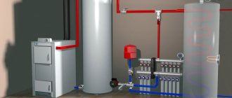
The efficiency of its further operation and service life depend on how correctly the piping of a solid fuel boiler is done. In operation, wood and coal heat generators differ from units using other types of fuel, and therefore require a special approach.
It is proposed to consider in detail how, after installing the heating wiring, to connect a solid fuel boiler, including with your own hands. A description of various schemes for connecting a TT boiler to a heating system can be found in this material.
What is the difference between solid fuel boilers
In addition to burning various types of solid fuel, heat generators have a number of differences from other heat sources. These features should be taken for granted and always taken into account when connecting a solid fuel boiler to a water heating system. What are they:
- High inertia. At the moment, there are no ways to quickly extinguish a solid fuel fire in a combustion chamber.
- Formation of condensation in the firebox during heating. The peculiarity is manifested due to the flow of coolant with a low temperature (below 50 ° C) into the boiler tank.
Note. The phenomenon of inertia is absent only in one type of solid fuel units - pellet boilers. They have a burner into which wood pellets are fed in doses; after the supply is stopped, the flame goes out almost immediately.
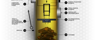
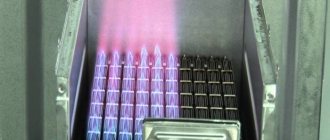
Diagram of the design of a direct combustion TT boiler with forced air injection.
Inertia creates the danger of overheating the water jacket of the heater, as a result of which the coolant in it boils. Steam is generated, which creates high pressure, rupturing the body of the unit and part of the supply pipeline. As a result, there is a lot of water in the furnace room, a lot of steam and a solid fuel boiler unsuitable for further use.
A similar situation can arise when the heat generator piping is done incorrectly. After all, in fact, the normal operating mode of wood-burning boilers is maximum; it is at this time that the unit reaches its rated efficiency. When the thermostat reacts to the coolant reaching a temperature of 85 °C and closes the air damper, combustion and smoldering in the firebox still continues. The water temperature rises another 2-4 °C, or even more, before its growth stops.
In order to avoid excess pressure and a subsequent accident, an important element is always involved in the piping of a solid fuel boiler - a safety group, which will be discussed in more detail below.
Another unpleasant feature of the unit operating on wood is the appearance of condensation on the inner walls of the firebox due to the passage of not yet heated coolant through the water jacket. This condensate is not God’s dew at all, since it is an aggressive liquid that quickly corrodes the steel walls of the combustion chamber. Then, having mixed with the ash, the condensate turns into a sticky substance that is not so easy to tear off from the surface. The problem is solved by installing a mixing unit in the piping circuit of a solid fuel boiler.
This coating serves as a heat insulator and reduces the efficiency of a solid fuel boiler.
It is too early to breathe a sigh of relief for owners of heat generators with cast iron heat exchangers that are not afraid of corrosion. Another misfortune may await them - the possibility of destruction of cast iron from temperature shock. Imagine that in a private house the electricity was turned off for 20-30 minutes and the circulation pump driving water through the solid fuel boiler stopped. During this time, the water in the radiators has time to cool down, and in the heat exchanger it has time to heat up (due to the same inertia).
Electricity appears, the pump turns on and directs the cooled coolant from the closed heating system into the heated boiler. Due to a sharp temperature change, the heat exchanger experiences a temperature shock, the cast iron section cracks, and water runs onto the floor. It is very difficult to repair; it is not always possible to replace a section. So even in this situation, the mixing unit will prevent an accident, which will be discussed below.
Emergency situations and their consequences are described not with the aim of scaring users of solid fuel boilers or encouraging them to purchase unnecessary elements of piping schemes. The description is based on practical experience, which must always be taken into account. If the heating unit is connected correctly, the likelihood of such consequences is extremely low, almost the same as with heat generators using other types of fuel.
Adding cold water to the heating system with a TT boiler
To mix cold water into the heating system, a three-way valve is used for a solid fuel boiler. This device allows you to maintain the set temperature in the following systems:
- Heating system with heat accumulator.
- Low temperature heating system with heated floors.
A three-way valve for a solid fuel boiler mixes cold water from the return into the hot water supply from the boiler, thereby regulating the overall supply temperature. If the supply temperature to the heated floors is set at 45 degrees Celsius, and at the outlet from the boiler, for example, 70 degrees Celsius, the three-way valve will mix hot water from the supply and cooled water from the return to the desired value.
To effectively use a three-way valve for a solid fuel boiler, you need to install it after the heat accumulator. In this case, the boiler at full power will heat the water in the heat accumulator, and the three-way valve will mix hot water from the heat accumulator with cold water from the return.
Solid fuel boiler wiring diagram:
More on this topic on our website:
- Scheme of a simple pyrolysis boiler - making a pyrolysis boiler with your own hands The energy market has never been highly stable. Constant fluctuations in the prices of major fuels such as oil and natural gas…
- Installing a solid fuel boiler with your own hands - correct connection and piping Here, three opponents in the comments are telling me that installing a solid fuel boiler with your own hands cannot be done. What…
- Do it yourself long-burning solid fuel boiler - drawings If you want to make a long-burning solid fuel boiler with your own hands, the drawings and diagrams on this page will help you with this...
- Do-it-yourself long-burning wood-burning boilers for the home - photo Look at what long-burning wood-burning boilers you can make for the home with your own hands - the photos on this page show several...
How to connect a solid fuel boiler
The canonical connection diagram for a solid fuel boiler contains two main elements that allow it to function reliably in the heating system of a private home. This is a safety group and a mixing unit based on a three-way valve with a thermal head and a temperature sensor, shown in the figure:
The always open output of the mixing valve (the left pipe in the diagram) must be directed to the pump and heat generator, otherwise there will be no circulation in the small boiler circuit
Note. The expansion tank is not shown here - it must be connected to the return line of the heating system in front of the pump (in the direction of water flow).
The presented diagram shows how to connect the unit correctly and is used with any solid fuel boilers, including pellet ones. You can find various general heating schemes - with a heat accumulator, an indirect heating boiler or a hydraulic arrow, in which this unit is not shown, but it must be there. The method of protecting against moisture loss in the firebox is discussed in detail in the video:
The task of the safety group, installed directly at the outlet of the supply pipe of a solid fuel boiler, is to automatically relieve pressure in the network when it rises above a set value (usually 3 Bar). This is done by a safety valve, and in addition to it, the element is equipped with an automatic air vent and a pressure gauge. The first releases the air appearing in the coolant, the second serves to control the pressure.
Attention! The installation of any shut-off valves is not allowed on the section of the pipeline between the safety group and the boiler. If you installed a ball valve to cut off and repair group parts, remove the handle from the stem.
How the scheme works
The mixing unit, which protects the heat generator from condensation and temperature changes, operates according to the following algorithm, starting from kindling:
- The firewood is just starting to burn, the pump is on, the valve on the side of the heating system is closed. The coolant circulates in a small circle through the bypass.
- When the temperature in the return pipeline rises to 50-55 °C, where the attached remote-type sensor is located, the thermal head, at its command, begins to press the three-way valve stem.
- The valve slowly opens and cold water gradually enters the boiler, mixing with hot water from the bypass.
- As all the radiators warm up, the overall temperature increases and then the valve closes the bypass completely, passing all the coolant through the heat exchanger of the unit.
An important nuance. Paired with a 3-way valve, a special head with a sensor and capillary is installed, designed to regulate the water temperature in a certain range (for example, 40...70 or 50...80 degrees). A regular radiator thermal head will not work.
This piping scheme is the simplest and most reliable; you can easily install it yourself and thus ensure the safe operation of the solid fuel boiler. There are a couple of recommendations regarding this, especially when piping a wood-burning heater in a private house with polypropylene or other polymer pipes:
- Make the section of the pipe from the boiler to the safety group from metal, and then lay plastic.
- Thick-walled polypropylene conducts heat poorly, which is why the surface-mounted sensor will openly lie, and the three-way valve will lag. For correct operation of the unit, the area between the pump and the heat generator, where the copper flask is located, must also be metal.
Connecting with copper pipes will not protect polypropylene from destruction in the event of overheating of the TT boiler.
But it will allow the temperature sensor and safety valve on the safety group to work correctly. Another point is the installation location of the circulation pump. It is best for him to stand where he is shown in the diagram - on the return line in front of the wood-burning boiler. In general, you can install the pump on the supply side, but remember what was said above: in an emergency, steam may appear in the supply pipe.
The pump is unable to pump gases, so when the chamber is filled with steam, the impeller will stop and the coolant circulation will stop. This will speed up a possible explosion of the boiler, because it will not be cooled by water flowing from the return.
Way to reduce the cost of strapping
The condensate protection circuit can be reduced in cost by installing a three-way mixing valve of a simplified design that does not require connecting an overhead temperature sensor and thermal head. It already has a thermostatic element installed, set to a fixed mixture temperature of 55 or 60 °C, as shown in the figure:
Special 3-way valve for solid fuel heating units HERZ-Teplomix
Note. Similar valves, which maintain a fixed temperature of mixed water at the outlet and are intended for installation in the primary circuit of a solid fuel boiler, are produced by many well-known brands - Herz Armaturen, Danfoss, Regulus and others.
Installing such an element definitely allows you to save on piping the TT boiler. But in this case, the possibility of changing the temperature of the coolant using a thermal head is lost, and its deviation at the output can reach 1-2 °C. In most cases, these shortcomings are insignificant.
Typical strapping schemes
For proper heating piping, it is necessary to develop an individual project, since each living space and boiler room are individual, although they have a number of similar features. Such projects are based on standard diagrams that reflect the fundamental positions of installation of systems in various conditions that are common to all.
Open type system with natural circulation
This scheme, otherwise gravitational, is the most common. It has its advantages and disadvantages.
Positive sides:
- Effective work.
- Easy to install.
- Relatively low cost.
- High security.
- Autonomy.
Since water tends to expand when heated, in a gravity scheme it is necessary to install an expansion tank that collects excess coolant.
Negative sides:
- Difficult to manage.
- The need for constant monitoring of the system.
- Increased fuel consumption.
In an open system, the return inlet to the boiler must be at least 0.5 meters below the radiators.
Closed system with natural coolant movement
Unlike open, here it is necessary to install a membrane tank on the return pipeline. For effective operation, its size must exceed by 10% the volume of coolant in the system as a whole.
To be able to relieve excess pressure from pipelines (more than 2 atm), a safety valve should be installed by connecting it to the sewer system.
Forced circulation system
A forced circulation system is distinguished by the fact that it includes a pump. This ensures uniform temperature in all areas. In addition, the use of circulation equipment makes it possible to minimize pipeline slopes.
To maintain the functionality of the heating in cases of voltage drop or pump failure, it is necessary to provide bypass lines bypassing the equipment. The circulation pump is installed on the return line for safety reasons, as well as to increase the degree of reliability and durability of operation.
Circuit with buffer capacitance
The piping scheme of a solid fuel heating boiler with a heat accumulator is used to maintain a constant temperature in the system (TTKs are poorly controlled, requiring constant monitoring of the amount of fuel and draft) and to avoid boiling of the working fluid.
The heat accumulator is a hermetically sealed tank installed between the boiler and the consumer. The operating principle of the device is to accumulate excess heat in its own volume, releasing it into the system when necessary.
The temperature of the coolant is regulated by means of a mixing unit, which is a three-way valve with a temperature sensor.
Trim with three-way valve
To additionally protect the heating boiler from overheating, a circuit is provided for emergency supply of cold water to the heat exchanger or to a special coil installed inside the equipment.
The operation of this unit is carried out thanks to the equipment of a three-way valve and a temperature sensor inside the heat exchanger. The heated water is discharged into the sewer.
With installation of an indirect heating boiler
The connection of a solid fuel boiler with an indirect heating boiler is suitable for any connection scheme. The boiler is used to heat cold water for hot water supply.
The water heater is connected to the system in parallel with all devices that use hot water. It is important to remember here that to increase the efficiency of its operation, a three-way valve should be provided to shut off the drainage of water from the unit if it has not yet heated up.
Collector circuit
Collectors are used for simultaneous parallel connection of several heating branches. For example, when connecting a heated floor to one unit, heating radiators on several floors (a separate branch for each), etc.
Despite the obvious complexity, the use of collectors (combs) opens up wide opportunities for adjusting the system, increasing efficiency and reliability.
Trim option with buffer tank
The presence of a buffer tank is extremely desirable for the operation of a boiler using solid fuels and here’s why. In order for the unit to function efficiently and produce heat with the efficiency declared in the passport (from 75 to 85% for different types), it must operate at maximum mode. When the air damper is closed to slow down combustion, there is a lack of oxygen in the firebox and the efficiency of wood burning decreases. At the same time, emissions of carbon monoxide (CO) into the atmosphere increase.
For reference. It is because of emissions that in most European countries it is prohibited to operate solid fuel boilers without a buffer tank.
On the other hand, at maximum combustion, the temperature of the coolant in modern heat generators reaches 85 ° C, and one load of firewood lasts only 4 hours. This does not suit many owners of private houses. The solution to the problem is to install a buffer tank and connect it to the TT boiler piping so that it serves as a storage tank. Schematically it looks like this:
By measuring the temperatures T1 and T2, you can configure the layer-by-layer loading of the container with a balancing valve
When the firebox is burning with all its might, the buffer tank accumulates heat (in technical language, it is loaded), and after extinguishing it releases it into the heating system. To control the temperature of the coolant supplied to the radiators, a three-way mixing valve and a second pump are also installed on the other side of the storage tank. Now it is not at all necessary to run to the boiler every 4 hours, because after the firebox goes out, the heating of the house will be provided for some time by the buffer tank. How long depends on its volume and heating temperature.
Reference. Based on practical experience, the capacity of a heat accumulator can be determined as follows: for a private house with an area of 200 m², you will need a tank with a volume of at least 1 m³.
There are a couple of important nuances. In order for the piping circuit to work safely, you need a solid fuel boiler whose power is sufficient for simultaneous heating and loading of the buffer tank. This means that power will be required 2 times higher than the calculated one. Another point is to select the pump performance so that the flow rate in the boiler circuit is slightly higher than the amount of water flowing in the heating circuit.
An interesting option for connecting a TT boiler with a homemade buffer tank (aka an indirect heating boiler) without a pump was demonstrated by our expert in the video:
Joint connection of two boilers
To increase the heating comfort of a private home, many owners install two or more heat sources that run on different energy sources. At the moment, the most relevant combinations of boilers are:
- natural gas and wood;
- solid fuel and electricity.
Accordingly, the gas and solid fuel boiler must be connected in such a way that the second automatically replaces the first after burning the next portion of firewood. The same requirements are put forward for connecting an electric boiler to a wood boiler. This is quite simple to do when a buffer tank is involved in the piping scheme, since it simultaneously plays the role of a hydraulic arrow, as shown in the figure.
The boiler supply lines are connected to the upper pipes of the heat accumulator, the return pipes to the lower ones
Advice. Information on calculating the volume of the buffer tank can be found in a separate publication.
As you can see, thanks to the presence of an intermediate storage tank, 2 different boilers can serve several heating distribution circuits at once - radiators and heated floors, and in addition load an indirect heating boiler. But not everyone installs a heat accumulator with a TT boiler, since this is not a cheap pleasure. In this case, there is a simple diagram, and you can install it yourself:
The circuit takes into account the peculiarity of the electric boiler - the built-in circulation pump always works
Note. The scheme is valid for both electric and gas heat generators operating together with solid fuel.
Here the main source of heat is a wood heater. After a stack of firewood burns out, the air temperature in the house begins to drop, which is registered by the room thermostat sensor and immediately turns on heating by the electric boiler. Without a new load of firewood, the temperature in the supply pipe decreases and the overhead mechanical thermostat turns off the pump of the solid fuel unit. If you ignite it after some time, everything will happen in the reverse order. This video is described in detail about this joint connection method:
Hot water from the heating boiler
Climatic offers a wide range of heating boilers of various types and countries of production - Russia, Germany, Italy, Czech Republic, etc. Read the information or call our consultants to choose the right boiler model.
A heating boiler is a device that, using the combustion of fuel (or electricity), heats the coolant for water heating of premises through a system of batteries and radiators. The boilers are designed for heating rooms with an area of 30 sq. m. m and up to several thousand. Household low-power heating boilers are used for heating and hot water supply of private and country houses, cottages, dachas, garages, workshops, cafes and restaurants, schools and other educational and children's institutions, as well as swimming pools, baths and saunas. In addition, they are used for individual apartment heating. Production and industrial boilers are designed for heating workshops, warehouses, hangars, enterprises, and other large buildings and premises. For very large objects in the heating system, it is allowed to combine boilers in a cascade of two or more devices. Small and simple heating boilers can be placed in the basement, attic, garage, even in the kitchen and bathroom. Installation of high-power floor-standing boilers is recommended in a separate boiler room. Some boiler models have outdoor (outdoor) installation.
Modern boilers of the new generation are equipped with programmable control units with various automatic settings and functions (for example, a weather-dependent control system), as well as devices for remote control of the boiler - a GSM module (regulation of the operation of the device via SMS messages).
The selection of heating boilers is carried out according to the main parameters: required heating area and boiler power, type of energy carrier, number of heating circuits, type of combustion chamber, type of burner, type of installation, steel or cast iron heat exchanger, etc.
To determine the power of a heating boiler for heating a house or apartment, a simple formula is used - 1 kW of boiler power to heat 10 m2 of a well-insulated room with a ceiling height of up to 3 m. Accordingly, if heating a basement, a glassed-in winter garden, rooms with non-standard ceilings, etc. is required .P. The boiler power must be increased. It is also recommended to increase the power (about 20-50%) when providing a boiler and hot water supply (especially if it is necessary to heat the water in the pool). Our consultants will help you accurately calculate the boiler power based on the heating area.
Comparison of heating boilers by type of fuel:
1. Gas boilers
– the optimal choice in the presence of main gas or liquefied gas)
(+) low cost of use (+) popularity (+) many options for manufacturers and costs (-) the need for constant availability of gas (-) strict installation requirements
2. Electric boilers
– the optimal choice when there is no gas and the necessary electrical power is available
(+) convenience, safety and environmental friendliness (+) low price (+) minimum installation requirements, do not require a boiler room (-) high cost of electricity (-) separate reliable electrical wiring with sufficient power is required
3. Solid fuel boilers
(firewood, coal, coke, etc.):
(+) simple and reliable device (+) low price (-) the need for a chimney and fuel supply (-) constant fuel loading and control is required
4. Liquid fuel boilers
(diesel fuel, fuel oil, kerosene, etc.)
(+) simple and inexpensive device (+) does not require approval during installation (-) increased noise during operation (-) electrical dependence (-) problems with operation at low temperatures
5. Combined or Multi-fuel boilers
– several types of fuel at once (gas, coal, liquid fuel, etc.)
(+) heating without interruptions (+) selection of the most profitable type of fuel at the moment (-) higher price than a “mono” boiler (-) purchase of several types of fuel
Detailed information about each type of boiler can be found in the links below.
If you need maximum reliability, consider installing two boilers in your heating system: the main one and a second backup boiler, which will take over all functions during cleaning, repair or replacement of the main boiler. Quite often, an electric boiler is installed as a backup option.
The heating boiler can have one (for heating only) or two circuits (heating and hot water supply, DHW). An indirect heating boiler (from 100 to 3000 liters at the buyer’s choice) can be connected to a single-circuit boiler to provide hot water. You can also pay attention to boilers with an already built-in boiler. Double-circuit hot water boilers heat water in a flow-through manner and provide continuous water supply; their productivity is quite high and is measured in l/min or l/hour. There are boilers that are connected and provide the function of a warm water floor.
The most economical and efficient boilers are condensing boilers
. Thanks to the use of modern technologies, the efficiency of such boilers is 10-11% higher than that of conventional ones. The advantages of condensing boilers are exceptional efficiency and cost-effectiveness compared to conventional ones, the disadvantages are the high price and the need for constant removal of condensate that forms in the heat exchanger.
The cost of a heating boiler may vary. In the Russian market of household and industrial boilers, of course, there are leaders in the high price category, for example, German and Swedish boilers, as well as inexpensive simple boilers - Russian and Chinese. The best boiler manufacturers are represented by a wide list:
“Premium class” - the most reliable and good boilers for homes, easy to operate, extremely durable, the kit is assembled like a “construction set”, but more expensive than others. Such manufacturers include the companies Buderus and Viessmann, which manufacture boilers in Germany.
“Middle class” - average price, not so prestigious, but quite reliable, standard standard solutions are presented. These are Italian boilers Ariston, Hermann and Baxi, Swedish Electrolux, German Unitherm and boilers from Slovakia Protherm.
"Economy class" - inexpensive and simple boilers, the service life is shorter than that of boilers of a higher category. Some manufacturers have budget boiler models, for example, Ferroli or domestic Neva Lux.
The division as a whole is arbitrary. You can simply tell the consultants of the Termomir boiler sales company your planned purchase budget and they will offer you several suitable options. Feel free to ask questions - and we will be able to select exactly the equipment you need.
See also:
- All heating boilers
- How to choose an electric boiler
- How to choose a gas boiler
- How to choose a solid fuel boiler
- Combined (multi-fuel) boilers - briefly about the main thing
- Boilers for boilers - how to choose
- Gas boilers
- Electric boilers
- Solid fuel boilers
- Diesel and combi boilers
- Boilers for heating boilers
- Automation for heating boilers
Need help choosing or haven't found the model you're looking for?
Call!
Tying using the method of primary and secondary rings
There is another way to combine a solid fuel boiler with an electric one to supply a large number of consumers. This is a method of primary and secondary circulation rings, which provides for hydraulic separation of flows, but without the use of a hydraulic needle. Also, for reliable operation of the system, a minimum of electronics is required, and a controller is not needed at all, despite the apparent complexity of the circuit:
The trick is that all consumers and boilers are connected to one primary circulation ring by both the supply and return pipelines. Due to the small distance between connections (up to 300 mm), the pressure drop is minimal compared to the pressure of the main circuit pump. Due to this, the movement of water in the primary ring does not depend on the operation of the secondary ring pumps. Only the temperature of the coolant changes.
Theoretically, any number of heat sources and secondary rings can be included in the main circuit. The main thing is to choose the right pipe diameters and the performance of the pumping units. The actual performance of the main ring pump must exceed the flow rate in the most “gluttonous” secondary circuit.
To achieve this, it is necessary to perform a hydraulic calculation and only then will it be possible to select the right pumps, so an ordinary homeowner cannot do without the help of specialists. In addition, it is necessary to link the operation of solid fuel and electric boilers by installing shut-off thermostats, as described in the following video:
Preparing the premises
In addition to covering the surfaces with insulation and casting the foundation, it is necessary to organize ventilation in the room, since the equipment takes oxygen to operate the burner from inside, and not from outside, the building.
For this, two holes are made: exhaust and supply. The first is recommended to be placed next to the boiler below, the second - under the ceiling on the opposite wall. It’s not bad if it comes from another room of the house. In this case, the air arrives already heated.
The cross-sectional diameter of the hood in cm2 is calculated by multiplying the boiler power in kW by 8. The supply duct should be slightly larger.
A solid fuel boiler must be connected to a vertical chimney that is led outside the building through a wall or roof. It is necessary to calculate and design a combustion product exhaust channel in advance by making a hole of the appropriate size for it.
Connection to the heating system
The boiler must be connected to the supply and return lines through shut-off valves, as this will ensure its unimpeded shutoff for repairs and maintenance. It is also necessary to place a circulation pump in front of the equipment (subject to the organization of a complex with forced movement of coolant), an expansion tank, and a safety group.
It is important to pay attention to ensuring measures to protect solid fuel from corrosion due to the formation of condensate.
To do this, it is necessary to maintain the temperature of the return line at a level not lower than 50-55 C. For this purpose, a three-way mixing valve is cut into it, mixing the heated coolant from the supply.
At the last stage, a test firing of the unit is carried out, designed to identify possible deviations in the functioning of the system, leaky connections, and insufficient draft in the chimney. Coping with the complex multi-stage task of installing a solid fuel boiler is often only possible for heating specialists.