Total, static and dynamic pressure. Measuring pressure in air ducts of ventilation systems
Total, static and dynamic pressure
When air moves through an explosive in any cross section, 3 types of pressure are distinguished:
Static pressure
determines the potential energy of 1 m 3 of air in the section under consideration.
It is equal to the pressure on the walls of the air duct. .
Dynamic pressure
– kinetic energy of the flow per 1 m3 of air.
– air density, – air speed, m/s.
Total pressure
equal to the sum of static and dynamic pressure.
It is customary to use the value of excess pressure, taking atmospheric pressure at the system level as a conditional zero. In discharge air ducts, total and static excess pressure is always “+”, i.e. pressure >
. In the suction air ducts, the total and static excess pressure is “-”.
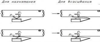
Measuring pressure in air ducts of ventilation systems
The pressure in the explosive is measured using a pneumometric tube and some measuring device: a micromanometer or other device.
For plenum duct:
static pressure – static pressure tube to the micromanometer tank;
total pressure – full pressure tube to the micromanometer tank;
dynamic pressure - the total pressure tube to the tank, and static pressure - to the capillary of the micromanometer.
For suction duct:
static pressure – static pressure tube to the pressure gauge capillary;
total pressure – total pressure tube to the capillary of the micromanometer;
dynamic pressure - the total pressure tube to the tank, and static pressure - to the capillary of the micromanometer.
Schemes for measuring pressure in air ducts.
Ticket No. 10
Pressure losses in ventilation systems
When moving along an explosive, air loses its energy to overcome various resistances, i.e. pressure loss occurs.
Friction pressure loss
– coefficient of friction resistance. Depends on the mode of movement of liquid through the air duct. — kinematic viscosity, depends on temperature.
In laminar mode:
in turbulent motion
depends on the roughness of the pipe surface. Various formulas are used and the Altschul formula is widely known: – absolute equivalent roughness of the material of the inner surface of the air duct, mm.
For sheet steel 0.1mm; silicate concrete slabs 1.5 mm; brick 4 mm, plaster on mesh 10 mm
Specific pressure loss
In engineering calculations, special tables are used in which the values are given
for round duct. For air ducts made of other materials, a correction factor is introduced and is equal to: .
Correction factor value
is given in the reference book depending on the type of material and the speed of air movement through the air duct.
For rectangular air ducts, the calculated value d is taken to be equivalent to dek, at which the pressure loss in a round air duct at the same speed will be equal to the pressure loss in a rectangular air duct:
— sides of a rectangular duct.
It should be kept in mind: the air flow of rectangular and round air ducts with
when the speeds are equal, it does not coincide.
Date added: 2018-02-18; ;
Source
Measuring atmospheric pressure using a thermohygrometer
Atmospheric pressure is measured not only using various types of barometers, but also with such universal digital instruments as thermohygrometers. Despite the fact that the main task of these devices is to determine relative humidity and temperature, they also do an excellent job of measuring air pressure, showing the most accurate values. Therefore, such multifunctional devices are much more profitable to purchase than outdated barometers and psychrometers.
JSC "EXIS" brings to your attention a huge range of electronic pressure meters and other high-quality control and measuring instruments and always at affordable prices.
In particular, in our company you can purchase the following models of thermohygrometers:
- Thermohygrometer IVTM-7 M 2-D-V
. The device, in addition to measuring and recording temperature and relative humidity of air and other non-aggressive gases, measures atmospheric pressure in millimeters of mercury and hPa, can record data in non-volatile memory, recalculate measurement results into various units (percentage of relative humidity, g/m3), carry out simultaneous indication of measured values. IVTM-7 M 2-D-V has a high degree of dust and moisture protection (IP65), making it possible to use it in rooms with high humidity. - Thermohygrometer IVTM-7 K-1
. The device measures atmospheric pressure in kPa, can recalculate the values of various humidity units, carry out simultaneous indication of measured values, record data on microSD, it is possible to connect various types of primary transducers. - Thermohygrometer IVTM-7 R-03-I-D
. The device is equipped with a liquid crystal indicator designed for visual monitoring of relative humidity, temperature and pressure values. It has small dimensions and an ergonomic body. - Thermohygrometer IVTM-7 M 6-D (in an ergonomic housing).
The device measures atmospheric pressure in kPa, can record data on a non-volatile memory card, recalculate measurement results into various units, and simultaneously display the measured values. It has an ergonomic body and a large and convenient display. - Thermohygrometer IVTM-7 M 3-D-V
. The device, in addition to measuring and recording temperature and relative humidity of air and other non-aggressive gases, measures atmospheric pressure in millimeters of mercury and hPa, can record data in non-volatile memory, recalculate measurement results into various units (percentage of relative humidity, g/m3), carry out simultaneous indication of measured values. Model IVTM-7 M3-D-V is intended for creating a measuring network. The degree of moisture protection of the housing and sensor is IP65, which makes it possible to use it in rooms with high humidity. - Thermohygrometer IVTM-7 M 6-D.
The device measures atmospheric pressure in kPa, can record data on a non-volatile memory card (microSD), recalculate measurement results into various units, and simultaneously display the measured values.
All models of thermohygrometers have a communication interface with a PC via USB, RS-232 and can be mounted on a wall.
Monitoring devices and methods for measuring pressures and air velocities in air ducts.
In a ventilation system, air moves through air ducts and overcomes resistance to movement due to the total pressure developed by the fan. Full R
The fan pressure is the sum of static
Pst
and high-speed
Psc
pressure.
High-speed pressure
Psk is spent on creating the required speed of air movement in the air duct, static
pressure Pst
is spent on overcoming the existing movement resistance (friction in various local resistances).
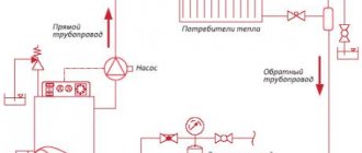
Rice. 1. Laboratory setup diagram
During technical tests of fans and dust collection units, the full P
n, static
Rst
and high-speed
Rsk
pressure.
When studying the speed regimes of air flows in different sections of air ducts, it is enough to determine the average values of the speed pressure P
ssr.
Control devices - micromanometer type MMN-4 (Fig. 2, a) and pneumometric tube (Fig. 2, b) are designed to measure total P
p, static
P
st and high-speed
P
c pressures.
rice.
2. Micromanometer type MMN-4 and pneumometric tube MIOT. a) – microammeter: 1 – frame; 2 – reservoir; 3 - fitting; 4 - three-way valve; 5 – tube; 6 tube tilt stand; 7- setscrew;
b) – MIOT pneumometric tube: 1 – hole for measuring the total Рп pressure; 2 – holes that perceive static pressure Pst.
The MMN-4 micromanometer has a stationary reservoir 2 connected to a rotating measuring tube 5 by a rubber hose. A three-way valve 4 is installed on the tank, with the help of which the micromanometer can be disconnected from the rubber tubes connected to it by setting valve 4 to position “0”.
Ventilation system pressure
For ventilation to be effective, you need to select the correct fan pressure. There are two options for measuring pressure yourself. The first method is direct, in which pressure is measured in different places. The second option is to calculate 2 types of pressure out of 3 and obtain an unknown value from them.
Pressure (also pressure) can be static, dynamic (speed) and total. According to the latter indicator, there are three categories of fans.
The first includes devices with pressure Formulas for calculating fan pressure
Pressure is the ratio of the acting forces and the area to which they are directed. In the case of a ventilation duct, we are talking about air and cross-section.
The flow in the channel is unevenly distributed and does not pass at right angles to the cross section. It will not be possible to find out the exact pressure from one measurement; you will have to look for the average value at several points. This must be done both for entering and exiting the ventilation device.
The total pressure of the fan is determined by the formula Pp = Pp (out) – Pp (in) , where:
- Pp (out) - total pressure at the outlet of the device;
- Pp (in.) - total pressure at the inlet to the device.
For fan static pressure, the formula differs slightly.
It is written as Rst = Rst (out) – Pp (in), where:
- Pst (out) - static pressure at the outlet of the device;
- Pp (in.) - total pressure at the inlet to the device.
Static pressure does not reflect the required amount of energy to transfer to the system, but serves as an additional parameter by which the total pressure can be determined. The last indicator is the main criterion when choosing a fan: both home and industrial. A decrease in total head reflects the loss of energy in the system.
The static pressure in the ventilation duct itself is obtained from the difference in static pressure at the inlet and outlet of the ventilation: Pst = Pst 0 – Pst 1 . This is a minor parameter.
The correct choice of a ventilation device includes the following nuances:
- calculation of air flow in the system (m³/s);
- selection of a device based on this calculation;
- determining the output speed for the selected fan (m/s);
- calculation of Pp device;
- measurement of static and dynamic pressure for comparison with total pressure.
To calculate the location for measuring the pressure, they are guided by the hydraulic diameter of the air duct. It is determined by the formula: D = 4F / P. F is the cross-sectional area of the pipe, and P is its perimeter. The distance to determine the measuring location at the inlet and outlet is measured by the number D.
Instruments for measuring atmospheric pressure
Today, there are several types of barometers that are used to measure air pressure:
- Mercury siphon barometer - represents a Y-shaped tube filled with mercury with an open and sealed end.
- Mercury cup barometer - consists of a vertical tube filled with mercury, the upper end of which is sealed, and the lower end is in a special cup with mercury.
- An aneroid barometer is an airless metal box with wavy walls.
- A barograph is a self-recording instrument that is used to monitor barometric pressure at certain periods of time.
- An electronic barometer is a digital device that operates on the principle of a conventional aneroid or on the principle of measuring air pressure on a sensitive crystal.
Mercury barometers are more accurate and reliable compared to aneroids; they are used to check the operation of other types of barometers. The height of pressure in them is determined by the height of the mercury column. Meteorological stations are equipped with cup barometers.
How to calculate ventilation pressure?
The total inlet pressure is measured at a cross-section of the ventilation duct located at a distance of two hydraulic duct diameters (2D). In front of the measurement point, there should ideally be a straight piece of air duct with a length of 4D and an undisturbed flow.
In practice, the conditions described above rarely occur, and then a honeycomb is installed in front of the desired location, which straightens the air flow.
Then a total pressure receiver is inserted into the ventilation system: at several points in the section in turn - at least 3. Based on the values obtained, the average result is calculated. For fans with a free input Pp, the input corresponds to the ambient pressure, and the excess pressure in this case is zero.
If you measure a strong air flow, then you should determine the speed from the pressure, and then compare it with the cross-sectional size. The higher the speed per unit area and the larger the area itself, the more efficient the fan.
Total outlet pressure is a complex concept. The outgoing flow has a heterogeneous structure, which also depends on the operating mode and type of device. The air at the outlet has zones of return movement, which complicates the calculation of pressure and speed.
It will not be possible to establish a pattern for the time of occurrence of such a movement. The flow heterogeneity reaches 7-10 D, but this figure can be reduced by straightening grids.
Sometimes there is a rotary elbow or a breakaway diffuser at the outlet of the ventilation device. In this case, the flow will be even more heterogeneous.
Features of pressure calculation
Measuring pressure in air becomes more difficult due to its rapidly changing parameters. You should buy electronic pressure gauges with a function for averaging the results obtained per unit of time. If the pressure jumps sharply (pulsates), dampers are useful to smooth out the differences.
The following principles should be remembered:
- total pressure is the sum of static and dynamic;
- the total pressure of the fan must be equal to the pressure loss in the ventilation network.
Measuring the static pressure at the outlet is not difficult. To do this, use a tube for static pressure: one end is inserted into the differential pressure gauge, and the other is directed into the section at the outlet of the fan. Based on the static pressure, the flow rate at the outlet of the ventilation device is calculated.
Dynamic pressure is also measured with a differential pressure gauge. Pitot-Prandtl tubes are connected to its connections. To one contact there is a tube for full pressure, and to the other - for static pressure. The result obtained will be equal to the dynamic pressure.
To find out the pressure loss in the air duct, you can monitor the flow dynamics: as soon as the air speed increases, the resistance of the ventilation network increases. Pressure is lost due to this resistance.
As the fan speed increases, the static pressure drops, and the dynamic pressure increases in proportion to the square of the increase in air flow. The total pressure will not change.
With a properly selected device, the dynamic pressure changes in direct proportion to the square of the flow rate, and the static pressure in inverse proportion. In this case, the amount of air used and the load of the electric motor, if they increase, will be insignificant.
Some requirements for the electric motor:
- low starting torque - due to the fact that power consumption changes in accordance with the change in the number of revolutions supplied to the cube;
- large stock;
- work at maximum power for greater savings.
The fan power depends on the total pressure, as well as on the efficiency and air flow. The last two indicators correlate with the throughput of the ventilation system.
At the design stage, you will have to set priorities. Take into account costs, loss of useful volume of premises, noise level.
Air resistance formula
In everyday life, we do not think at all about the air we breathe. But in fact, there is a force of air resistance that a person encounters when performing any actions every day.
This value is made up of various factors. These include drag, air turbulence, air-surface friction, internal resistance, induced resistance and various additional resistances. The main reasons that cause resistance include air friction and the formation of turbulence.
In each case, the strength of this resistance is calculated individually, based on existing conditions. For example, for a car, the aerodynamic drag indicator will be calculated using the formula F = Cx*S*V2*r/2, where C is the aerodynamic drag coefficient, S is the front surface area of the car, V is the speed, and r denotes the air density. Even here there will be many nuances and the results will even depend on the shape of the machine. Using this example, you can understand that this value depends on the body performing the action and on external indicators, such as density. Air density has a greater effect on objects that are in the airspace.
This formula allows you to measure the strength with which various factors influence resistance. This helps, for example, in production. To reduce the friction force on the product, roughness is reduced and more streamlined shapes are made. Our laboratory specialists can carry out the necessary calculations or other research. Microclimate research is also a very important and necessary procedure, and we are ready to carry it out using the most accurate equipment. Thanks to it, you can learn about air quality, humidity, temperature, speed and many other factors that affect human performance and health.