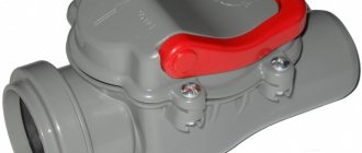
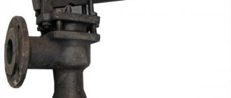
A standard heating system includes many elements. Each of them performs its own task, as a result of which the design works smoothly and accurately. One of these elements is a heating check valve that controls the flow of coolant.
We will introduce all types of check valves used today in the organization of heating circuits. The article we presented describes their design features in detail and provides technical characteristics. Do-it-yourselfers will find installation manuals and valuable advice here.
Why is a check valve needed?
During operation, hydraulic pressure appears inside the heating system, which may be different in different areas. The reasons for this phenomenon are very different.
Most often, this is uneven cooling of the coolant, errors in the design and assembly of the system, or its breakthrough. The result is always the same: the direction of the main fluid flow changes and it turns in the opposite direction.
This is fraught with very serious consequences, including the failure of the boiler, or even the entire system, which will require significant repair costs in the future.
For this reason, experts strongly recommend installing a check valve. The device is capable of passing liquid in only one direction. When reverse flow occurs, the locking mechanism is activated and the hole becomes impassable for the coolant.
Thus, the device is able to control the flow of liquid, passing it in only one direction.
The principle of operation of the check valve is very simple. It passes the coolant fluid in a given direction and blocks the path when it tries to move in the opposite direction
For normal operation of the system, it is necessary that the device does not create additional pressure and freely passes the coolant moving to the radiators. Therefore, it is extremely important to choose the right product.
Types of check valve
Despite the fact that all devices of this type perform the same task, they have structural and, therefore, operational differences. Let's take a closer look at each of these types.
Disc type devices
A distinctive feature of the product is the presence of a disc valve. This is a plastic or metal element, the dimensions of which allow it to completely block the flow of coolant if it begins to move in the opposite direction.
The disk is connected to a steel spring. When a liquid moves forward, it is in a compressed state. When changing direction, it straightens and moves the disk from its place, thereby blocking the pipe.
The valve design also includes a sealing gasket, which allows the valve mechanism to sit as tightly as possible in the seat. Therefore, leakage is excluded in serviceable devices.
Disc devices are widely used in the design of household heating systems, as they have significant advantages:
- Compactness. The dimensions of the products and their weight are small, which makes it possible to install them on any system.
- The device does not require regular maintenance.
- The cost of the device is low.
Among the significant shortcomings, it is worth noting that it is unsuitable for repair. Therefore, failed valves are immediately replaced with new ones.
A significant disadvantage of disk devices is significant hydraulic resistance. The diagram clearly shows how it arises. The liquid has to overcome an obstacle in the form of a locking disc
And one more minus is the significant hydraulic resistance created by the device. For some systems, such as a geothermal heat pump, this can be critical. Over time, the butterfly valve becomes covered with a layer of mineral deposits, which leads to failure of the device.
Standard butterfly valves create some shock loads when closing. This does not affect their performance and technical condition in any way, but water hammer occurs in the system. Which is not desirable for her.
Disk devices with an additional mechanism that allows closing the hole as smoothly as possible do not have this drawback. Their cost is higher than that of standard analogues.
Ball check valves
Devices of this type use a metal ball as a shutter. It is made from aluminum, steel and other metals. To extend the service life, the element is covered with a layer of rubber.
This valve works as follows: when the coolant moves through the body of the device in the desired direction, it lifts the ball, which moves into the upper compartment of the valve.
The ball-type valve has minimal hydraulic resistance, therefore it is widely used in a wide variety of heating systems. Another plus is long service life
As soon as the direction of movement changes or the flow stops, the ball immediately descends and blocks the pipe. Thus, the movement of fluid in the opposite direction becomes impossible.
The advantages of these valves include:
- reliability - the design does not include rubbing or moving systems, which significantly reduces the possibility of breakdown and allows you to work in any position;
- maintainability - the upper part of the valve body is equipped with a removable cover, which provides easy access to the interior of the structure;
- low hydraulic resistance.
Considering the disadvantages, it is worth noting the rather large working diameter. For this reason, it is impossible to use them in domestic pipelines of small cross-sections.
Ball valves are difficult to install due to their design features. When installed horizontally, they must be placed with the lid up, otherwise the shutter will not be able to rise to allow the flow of water to pass through. Based on the same considerations, when installing vertically, you must strictly ensure that the liquid moves strictly upward.
Ball valves will not be able to function normally in pipelines with low pressure. Because the minimum value at which the sphere blocking the passage opening rises is usually 25 bar.
Petal type of shutter
The shutter for this type of valve is a thin steel plate. It is attached to a hinged structure that allows it to move.
The double-leaf type reed check valve is very reliable and can withstand high pressure. But at the same time it exhibits serious hydraulic resistance, since the rotary axis of the valves is located directly in the center of the passage opening
There are two types of petal devices. Single-leaf or rotary are equipped with one plate that can rotate around an axis.
When the coolant moves in a given direction, it lifts the sash, thereby opening the passage hole. When the flow direction changes, the plate lowers. This can be done either with or without a spring.
Butterfly valves are designed slightly differently. They have two locking plates mounted on a rotating axis and located in the center of the passage opening.
The coolant moving along the heating circuit opens both flaps of the double-leaf check valve, and when the direction of its movement changes, the springs slam the plates
The advantages of using these valves are:
- some models of gravity valves can operate without springs, which allows them to be used in gravity systems;
- relatively low cost of devices.
Among the disadvantages, it is worth noting the rather high hydraulic resistance. This is especially true for double-leaf models - the rotary axis is located directly in the center of the passage opening, which is a significant obstacle to moving liquid.
For this reason, butterfly valves are used exclusively in high pressure systems.
Lifting equipment
Lift valves are equipped with a spool that can move freely relative to a vertical axis. On the through hole there is a seat where the spool is located.
When liquid is supplied, the force of its pressure lifts the valve, and it moves along the axis, opening a hole for the movement of coolant. As soon as the flow pressure weakens or it changes its direction, the spool will lower into the seat.
The lift check valve can only be installed vertically. Otherwise, the pressure of the coolant liquid will not be enough to lift the locking mechanism
The advantages of these devices are:
- Reliability. The equipment has a fairly simple design, which allows it to operate with minimal risk of breakdown.
- Low sensitivity to coolant quality.
- Possibility of repairs. For this purpose, a removable cover is located in the upper part of the device body.
Among the disadvantages, installation limitations should be noted. Due to the design features, they can only be mounted in a strictly vertical position.
Rules for choosing a locking device
Choosing a check valve intended for a heating system is a responsible undertaking. If knowledge in this area is minimal, it is best to seek help from specialists. This will ensure that your new heating system is functional and safe.
You need to know that, regardless of their type, all check valves differ in the way they are connected to the pipeline.
Sleeve check valves are very easy to install. However, the threaded connection cannot withstand high pressure, so they have limitations in use
Coupling devices are equipped with a connecting threaded unit, which greatly facilitates their connection to the main line. Most often, such a unit is equipped with disc valves intended for installation in autonomous heating systems of an apartment or private house. Their distinguishing feature is their small diameter. Most often it is no larger than DU-50.
Flange products are a structure assembled on the basis of a part that has holes for fastenings. Using the latter, it is connected to the main pipeline. A flange connection is much stronger than a threaded connection.
For this reason, flanged valves are widely used in the construction of large-diameter pipelines. Ball type devices are most in demand.
Wafer devices are designed for installation between two pipe flanges. They are lightweight and compact. Very often, both types of reed-type valves are produced in wafer design.
On sale you can find check valves that are installed by welding. This option can be used, for example, when installing heating from polypropylene pipes.
Flanged type check valves are securely attached to the pipe. This connection can withstand high pressure, which allows the devices to be used in centralized pipelines
Another important selection criterion is the material from which the device is made. It could be stainless steel. This option is considered optimal for highways with a diameter of less than 0.04 m.
The metal is practically not subject to corrosion processes and can withstand loads of up to 10 atm. This allows the valve to operate in the system trouble-free and for a very long time, but its cost is quite high. Brass valves have a lower price. They are subject to corrosion, but this process occurs very slowly, which significantly increases their service life.
However, their mechanical strength is much lower than that of stainless steel. Nevertheless, they can withstand the loads that arise in a household network quite easily. The most durable valves are made of cast iron - they successfully cope with critical pressure values, have significant dimensions and impressive weight.
Due to the nature of production, only body parts with a diameter greater than 40 mm can be made of cast iron. For this reason, they are used extremely rarely for the installation of autonomous heating systems.
It is desirable that not only the body, but also all internal elements of the check valve are made of metal. Plastic usually has less strength, which can lead to premature failure of the part.
When choosing a check valve, you need to remember one more rule - its diameter must exactly match the parameters of the passage hole. It is very important that the operating pressure of the system does not exceed the maximum permissible values for operation established by the manufacturer of the selected model.
Methods for installing heated floors without a collector
H2_2
The following materials and devices will be needed:
- Pipeline;
- Pipeline components;
- Boiler;
- Three-way thermostatic valve;
- Pump assembly.
Some people try to use the simplest installation method - to embed the underfloor heating system directly into the central heating system. However, this approach threatens serious damage to the pipeline, because The temperature for radiators is much higher than that needed for the floor. Also, if such a “homemade device” is discovered by supervisory authorities, the owner of the apartment faces serious penalties and an order to completely dismantle the warm water floor.
There are 2 preferred options for laying a pipeline without a collector: snail and snake. Moreover, both schemes must consist of a double pipeline: 2 parallel loops to the heated floor - supply and return.
The advantage of the “snake” is that you can distribute heating zones. For example, go around furniture or plumbing fixtures. The advantage of the “snail” is more uniform heating of the entire area.
After laying the pipeline, it must be connected to the boiler. You must first calculate the pump power. The following formula is used:
G =Q X 0.86/Δt,
where G is the system capacity (l/h),
Q - system power (W),
0.86 — conversion factor in Kcal/h,
Δt—flow-return temperature difference (°C).
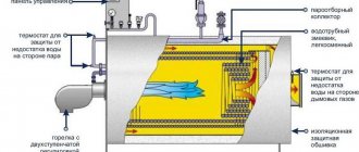
A pump is needed to ensure the speed of coolant movement through the pipes. Depending on the type of pump, it can be controlled either manually or automatically. The device is mounted on the supply pipeline. In a system without a mixing unit, the pump device is located under the boiler. The circuit between the pipeline with the pump and the boiler is closed by a three-way thermostatic valve.
In order for the heated floor to work stably without installing a mixing unit, you should choose a high-quality, powerful boiler. Electric or gas – it doesn’t really matter. The main thing is that the power of the device is designed specifically for the designed heated floor. Experts recommend choosing models with a pump.
Options for working connection schemes
Heating systems are very diverse and the presence of a check valve is not necessary in all of them. Let's consider several cases when its installation is necessary. First of all, a check valve must be installed on each of the individual circuits in a closed circuit, provided that they are equipped with circulation pumps.
Some craftsmen strongly recommend installing a spring-type check valve in front of the inlet pipe of the only circulation pump in a single-circuit system. They motivate their advice by the fact that in this way pumping equipment can be protected from water hammer.
This is in no way true. Firstly, installing a check valve in a single-circuit system is hardly justified. Secondly, it is always installed after the circulation pump, otherwise using the device loses all meaning.
If two or more boilers are included in the heating circuit, the occurrence of parasitic flows is inevitable. Therefore, connecting a check valve is mandatory
For multi-circuit systems, the presence of a reverse-acting shut-off device is vital. For example, when two boilers are used for heating, electric and solid fuel, or any others.
When one of the circulation pumps is turned off, the pressure in the pipeline will inevitably change and a so-called parasitic flow will appear, which will move in a small circle, which can lead to trouble. It is impossible to do without shut-off valves here.
A similar situation arises when using an indirect heating boiler. Especially if the equipment has a separate pump, if there is no buffer tank, hydraulic arrow or distribution comb.
Here, too, there is a high probability of a parasitic flow, to cut off which a check valve is needed, which is used specifically for arranging a branch with a boiler.
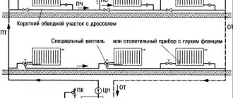
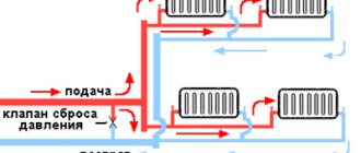
It is mandatory to use shut-off valves in systems with bypass. Such schemes are usually used when converting a scheme from gravitational fluid circulation to forced circulation.
In this case, the valve is placed on the bypass parallel to the circulation pumping equipment. It is assumed that the main mode of operation will be forced. But if the pump is turned off due to lack of electricity or breakdown, the system will automatically switch to natural circulation.
When installing bypass units for heating circuits, the use of check valves is considered mandatory. The figure shows one of the possible bypass connection options
This will happen as follows: the pump stops supplying coolant, the check valve actuator unit ceases to experience pressure and closes.
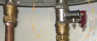
Then the convection movement of the liquid along the main line resumes. This process will continue until the pump starts working. In addition, experts suggest installing a check valve on the make-up pipeline. This is not necessary, but highly desirable, since it allows you to avoid emptying the heating system for a variety of reasons.
For example, the owner opened a tap on the make-up pipeline to increase the pressure in the system. If, by an unpleasant coincidence, the water supply is cut off at this moment, the coolant will simply squeeze out the remaining cold water and go into the pipeline. As a result, the heating system will be left without liquid, the pressure in it will drop sharply and the boiler will stop.
In the circuits described above, it is important to use the correct valves. To cut off parasitic flows between adjacent circuits, it is advisable to install disk or petal devices. In this case, the hydraulic resistance will be lower in the latter option, which must be taken into account when choosing.
In heating systems with natural coolant circulation, the use of spring check valves is impractical. Only paddle rotators can be installed here
To install a bypass unit, it is preferable to choose a ball valve. This is due to the fact that it provides almost zero resistance. A disc-type valve can be installed on the make-up pipeline. This should be a model designed for fairly high operating pressure.
Therefore, a check valve may not be installed in all heating systems. It is necessarily used when installing bypasses of all types for boilers and radiators, as well as at pipeline branch points.
Types of heating systems with gravity circulation
Despite the simple design of a water heating system with self-circulation of coolant, there are at least four popular installation schemes. The choice of wiring type depends on the characteristics of the building itself and the expected performance.
To determine which scheme will work, in each individual case it is necessary to perform a hydraulic calculation of the system, take into account the characteristics of the heating unit, calculate the diameter of the pipe, etc. You may need professional help when performing the calculations.
Closed system with gravity circulation
In EU countries, closed systems are the most popular among other solutions. In the Russian Federation, the scheme has not yet received widespread use. The operating principles of a closed-type water heating system with pumpless circulation are as follows:
- When heated, the coolant expands and water is displaced from the heating circuit.
- Under pressure, the liquid enters a closed membrane expansion tank. The design of the container consists of a cavity divided by a membrane into two parts. One half of the tank is filled with gas (most models use nitrogen). The second part remains empty for filling with coolant.
- When the liquid is heated, pressure is created sufficient to push through the membrane and compress the nitrogen. After cooling, the reverse process occurs and the gas squeezes water out of the tank.
Otherwise, closed-type systems work like other heating schemes with natural circulation. The disadvantages include the dependence on the volume of the expansion tank. For rooms with a large heated area, you will need to install a spacious container, which is not always advisable.
Open system with gravity circulation
The open type heating system differs from the previous type only in the design of the expansion tank. This scheme was most often used in old buildings. The advantage of an open system is the ability to independently manufacture a container from scrap materials. The tank usually has modest dimensions and is installed on the roof or under the ceiling of the living room.
The main disadvantage of open structures is the entry of air into pipes and heating radiators, which leads to increased corrosion and rapid failure of heating elements. Airing of the system is also a frequent “guest” in open-type circuits. Therefore, radiators are installed at an angle; Mayevsky valves must be provided to bleed air.
Single-pipe self-circulating system
This solution has several advantages:
- There is no pair pipeline under the ceiling and above the floor level.
- Saves money on system installation.
The disadvantages of this solution are obvious. The heat transfer of heating radiators and the intensity of their heating decreases with distance from the boiler. As practice shows, a single-pipe heating system for a two-story house with natural circulation, even if all slopes are observed and the correct pipe diameter is selected, is often redone (by installing pumping equipment).
Two-pipe self-circulating system
A two-pipe heating system in a private house with natural circulation has the following design features:
- Supply and return flow through different pipes.
- The supply pipeline is connected to each radiator through an inlet branch.
- The second line connects the battery to the return line.
As a result, a two-pipe radiator-type system provides the following advantages:
- Even heat distribution.
- No need to add radiator sections for better heating.
- Easier to adjust the system.
- The diameter of the water circuit is at least one size smaller than in single-pipe circuits.
- Lack of strict rules for installing a two-pipe system. Small deviations regarding slopes are allowed.
The main advantage of a two-pipe heating system with bottom and top wiring is the simplicity and at the same time efficiency of the design, which allows you to eliminate errors made in calculations or during installation work.
Nuances of proper installation
During the installation of shut-off valves, several rules should be strictly followed:
- The valve is installed strictly in the direction of coolant flow. To avoid mistakes, the product body must be marked with an arrow indicating the working direction.
- Paronite gaskets can be used to seal connections, provided that they do not reduce the diameter of the passage hole. Otherwise, the valve will exert more hydraulic pressure than intended.
- The device must be installed so that other elements of the heating system do not exert additional pressure on its body.
- It is highly advisable to install a mesh in front of the check valve for rough cleaning. This will make it possible to prevent solid particles from entering the locking mechanism, which, in turn, can lead to a violation of the tightness of the device when closed.
Another important point: before installation, you need to once again make sure that the valve is selected correctly.
For example, for schemes with forced circulation, any type of device is suitable, but for gravitational systems, only a rotary petal device without a spring. Since the coolant moving by gravity will not be able to cope with the resistance of the spring.
Pumping groups (quick installation groups)
When installing a radiator heating system or “warm floors” in a country house, installers are faced with many problems associated with the selection and reliable connection of circulation pumps, ball valves, thermometers, check valves and other components. Installation is greatly simplified and time-shortened if you use ready-made pump groups, or, as they are also called, quick installation groups.