Computational modeling
The most constructive and correct adjustment method is by constructing a calculation model of the hydraulic heating system.
This can be done in software such as Danfoss CO and Valtec.PRG, or in paid products such as AutoSnab 3D. You should not be afraid of paid software: as you will see later, its cost cannot be compared with the costs of special automatic balancing devices, while the design design of the hydraulic system will provide a complete picture of the system, its operating modes and the physical processes occurring at each point . Balancing using software calculations is carried out by constructing an exact virtual copy of the heating system. In different working environments, the modeling mechanism proceeds with some differences, however, all programs of this kind have a friendly and user-friendly interface
It is very important that the construction is carried out truly accurately: indicating each fitting, fitting element, turns and branches present in the real system. Here are the initial data you will need:
- Boiler specifications: power, efficiency, pressure-flow curve, operating pressure.
- information about the circulation pump: flow rate and pressure;
- coolant type;
- material and nominal diameter of pipes, ambient temperature;
- technical information about all shut-off and control valves, local resistance coefficients (KMR) of each element;
- passport data for shut-off valves, the dependence of their capacity on pressure drop and degree of opening.
After building a system model, all work comes down to ensuring equal coolant flow on each radiator. To do this, artificially reduce the throughput of shut-off valves on those radiators and circuits where there is a significant increase in flow compared to others. When virtual balancing is completed, Kvs - throughput coefficients - are written out for each radiator. Using a table or graph from the valve data sheet, the required number of revolutions of the adjusting rod is determined, after which this data is used to balance the real system in situ.
Valve setting
Setting the required value of the throughput of the fittings is carried out by changing the position of the handle. To ensure the most accurate adjustment, it is better to use a special flow meter or instruction table with pressure drop and flow rates. After setting the desired value, the shutter position can be locked by simply pressing the handle. To protect against unauthorized changes to the set parameters, it is recommended to seal the device.
is ready to provide qualified assistance in the selection of manual balancing valves, as well as their supply, installation and configuration. We will find the optimal solution for heating and cooling systems of any scale and configuration.
Balancing valve for heating system
Existing heat supply systems are conventionally divided into two types:
- Dynamic. They have conditionally constant or variable hydraulic characteristics, these include heating lines with two-way control valves. These systems are equipped with automatic balancing differential regulators.
- Static. They have constant hydraulic parameters, include lines with or without three-way adjustment valves, the system is equipped with static manual balancing valves.
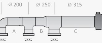
Rice. 7 Balancing valve in the line - installation diagram of automatic fittings
In a private house
In a private house, a balance valve is installed on each radiator; the outlet pipes of each of them must have union nuts or another type of threaded connection. The use of automatic systems does not require adjustment - when using a two-valve design, the supply of coolant to radiators installed at a large distance from the boiler is automatically increased.
This occurs due to the transfer of water to the actuators through a pulse tube under lower pressure than that of the first batteries from the boiler. The use of another type of combined valves also does not require calculating heat transfer using special tables and measurements; the devices have built-in control elements, the movement of which occurs using an electric drive.
If a manual balancer is used, it must be adjusted using measuring equipment.
Rice. 8 Automatic balancing valve in the heating system - connection diagram
To determine the volume of water supplied to each radiator and, accordingly, balancing, an electronic contact thermometer is used, with which the temperature of all heating radiators is measured. The average supply volume per heater is determined by dividing the total value by the number of heating elements. The greatest flow of hot water should flow to the furthest radiator, a smaller amount to the element closest to the boiler. When carrying out adjustment work using a manual mechanical device, proceed as follows:
- Open all control valves all the way and turn on the water, the maximum surface temperature of the radiators is 70 - 80 degrees.
- Using a contact thermometer, measure the temperature of all batteries and record the readings.
- Since the furthest elements must be supplied with the maximum amount of coolant, they are not subject to further regulation. Each valve has a different number of revolutions and its own individual settings, so the easiest way is to calculate the required number of revolutions using the simplest school rules based on the linear dependence of the radiator temperature on the volume of passing coolant.
Rice. 9 Balancing fittings - installation examples
For example, if the operating temperature of the first radiator from the boiler is +80 C., and the last +70 C. with the same supply volumes of 0.5 m3/h, on the first heater this indicator is reduced by a ratio of 80 to 70, consumption will go less, and the resulting volume will be 0.435 m3/h. If all the valves are not set to the maximum flow, but set to the average value, then you can take the heaters located in the middle of the line as a guide and similarly reduce the throughput closer to the boiler and increase it at the farthest points.
In a multi-storey building or building
The installation of valves in a multi-storey building is carried out in the return line of each riser; if the electric pump is far away, the pressure in each of them should be approximately the same - in this case, the flow rate for each riser is considered equal.
To set up in an apartment building with a large number of risers, it uses data on the volume of water supplied by an electric pump, which is divided by the number of risers. The resulting value in cubic meters per hour (for the Danfoss LENO MSV-B valve) is set on the digital scale of the device by rotating the handle.
What is a balancing valve for?
As already mentioned, any heating circuit needs hydraulic adjustment - balancing. The purpose of such an operation is to bring the coolant flow in each branch of the circuit to the calculated value, so that along with it the required amount of heat is delivered to each radiator. When we talk about setting up the system, by default we mean that the coolant flow for each section is pre-calculated.
In the simplest schemes, the required flow rate is ensured by correctly selected pipe diameters. In more complex systems, adjustment was carried out with special washers with a passage size that ensured the flow of the required amount of water. But the listed methods are considered outdated; a more modern method is now used - installing balancing valves in the heating system. By its design, the device is a conventional manual valve, with the help of which quantitative regulation of the coolant is carried out. Only in addition to the flow shut-off mechanism, 2 fittings are built into the body. They serve for:
- measuring the pressure before and after the control mechanism;
- connecting the capillary tube and interacting with other control elements.
By measuring the pressure in each of the fittings, the magnitude of its drop across the regulator is determined, and then, based on this, the fluid flow in the area is calculated. The instructions included with the valve contain a graph that can be used to calculate the number of turns of the handle to ensure a certain water flow.
Products from some well-known manufacturers, for example, Danfoss balancing valves, can be measured using instruments of the same brand, which immediately show the amount of coolant flowing. This greatly simplifies the process; you do not need to do any calculations, although you will have to spend additional money on such equipment.
According to their purpose, devices are divided into manual valves and automatic regulators. In the second case, the device includes 2 devices: the balancing valve itself and the differential pressure regulator connected to it by a capillary tube.
What is the difference between a tap and a valve?
A standard balancing valve for regulating fluid flow is a cheap analogue of the original valve, which allows you to regulate the flow area more smoothly and accurately. Also, the second one has holes in its design for measuring the amount of liquid passed by a flow meter.
Another product that controls coolant flow is balancing valves. It works on the same principle as standard valves, although there are models with holes for measurements. The ability to take measurements is an important indicator for the correct installation of such devices, so when choosing products, focus on those that have holes in their design for this.
Principle of operation
Turning the adjustment handle changes the position of the valve spool. As a result, the size of the section between it and the saddle changes.
Thus, the coolant, passing through a large or small section of the valve, changes its pressure as the throughput changes. Thus, by adjusting the pressure, it is possible to achieve uniform heat distribution for each heating device.
To automatically adjust the heat distribution, two balancing valves are installed in the system - on the input circuit and in the return circuit. They are connected to each other. The balancing effect of the system will take place automatically.
But to do this, you will need to correctly adjust and configure the entire heating system at the very beginning, at the first start. If all the manufacturer's requirements are met, the balancing equipment works flawlessly.
Please note: some people mistakenly, on the advice of local “Kulibins,” try to install a ball valve instead of a balancing valve. The absurdity of such an idea becomes obvious immediately after the system is launched. The valve does not relate to the control valves on any side.
How to install
When performing installation, it is very important to ensure the required position of the valve. In this case, the arrow on the body must coincide with the direction of movement of the coolant
This position will ensure not only the required design resistance of the valve, but also the required flow. At the same time, it is worth noting that some manufacturers allow the possibility of installing the valve not only in the direction, but also against the flow. The rod, in most models, can occupy a different spatial position.
During the installation process, it is worth protecting the working parts of the fittings from various mechanical contaminants. To do this, you need to install a sump filter or a special filter in front of the valve. To eliminate turbulent fluid movement, it is necessary to provide straight sections of sufficient length before and after the valve. This requirement must be specified in the documentation for the valve.
A heating system equipped with a balancing valve must be filled in a special way. To do this, in systems equipped with dynamic valves, it is necessary to provide filling connections, which must be located in close proximity to the valve on the return pipeline. And the valves mounted on the supply pipeline must be carefully closed. To set the balancing valve, a special flow meter or differential pressure and flow tables are used. However, in any case, the initial calculation is performed at the stage of calculating the heating system.
Installation of balancing valves.
The installation of a balancing valve is carried out in the same way as the installation of ball valves. The position of the valve in space does not affect its operation, but you need to pay attention to the arrow, which indicates the recommended direction of flow. If it is mixed up, the valve will create greater resistance to the flow of coolant. Valves can be installed on both supply and return pipelines.
Operating temperature and pressure may vary depending on the specific model, so it is best to select the equipment you need using manufacturer catalogs. You can find them on the official websites of manufacturers.
Why do you carry out hydraulic adjustment of CO?
The main goal of balancing the heating system is the correct distribution of the amount of coolant to the radiators (batteries) per unit of time, directing the required amount of heat to places where there is a shortage.
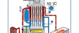
For a more complete understanding of the picture, imagine that in a certain area of the CO it is divided into two circuits, each of which leads to different rooms. Since the volume of the rooms is different, the length of the contour may vary. A circuit with a longer length (or more heating devices) has more hydraulic resistance. As you know, water (coolant) always follows the path of least resistance. In other words, according to physical laws, more heat will enter a shorter circuit than distant radiators. The figure clearly shows the distribution of thermal energy in two identical systems.
We should not forget that in an untuned CO the heat generator operates at maximum, which negatively affects all structural elements.
Summarizing the above, CO balancing is carried out for:
- Uniform heating of batteries, regardless of their location in the heating system.
- Economical operation of the boiler installation.
Advice! Balancing a two-pipe heating system (carried out with preliminary hydraulic calculations), of small length (no more than 4 heating devices) is optional
.
In all other cases, for efficient and economical operation of the CO, hydraulic adjustment is necessary!
Why is a balancing valve needed?
In modern large heating systems, uneven heating of different rooms is often observed. This is due to different coolant flow rates through the branches of the heating system. The coolant (like an electric current) tries to flow along the path of least resistance, therefore, at a great distance from the heat source (thermal unit or boiler), the flow rate should be less than near it. In order to equalize the coolant flow through different branches, balancing valves are used.
As can be seen from the top figure, the flow rate in heating circuits of different lengths will be different and the temperature in the rooms will also be strikingly different. Now let's talk about the types of balancing valves.
Installation and operation
Professionals leave a small gap in front of the valve and straight pipe. This prevents kinks from occurring that impede water movement. In order to protect against dirt and dust getting on the adjustment elements, a special filter is installed directly in front of the valve. Before installation, the pipe itself must be washed and checked for damage. Next, installation is carried out as follows:
- The master determines the area where the valve will be installed in the future. The dimensions of the straight pipe zones before and after the element must comply with the following parameters: 5 diameters in front of the part, 2 or more after it, as this eliminates turbulence.
- The valve is screwed into a pipe pre-equipped with tow. Thread cutting can be done with a die or other similar tool. The main thing is that it is at least 7 turns.
Installation of the valve is easily carried out according to the principle of installing a ball valve
How exactly the valve itself is placed in space is not particularly important. The main thing is that the arrow on the body corresponds to the direction of water flow
Otherwise, the part will contribute to fluid resistance.
Valve installation features
Correct installation of the valve is the key to stable operation of the balancing valve and the entire pipeline system. Therefore, when installing the device, you need to consider the following recommendations:
- the valve can be installed on horizontal and vertical parts of the pipeline after preliminary preparation - cleaning;
- in order to correctly position the valve, it is necessary to ensure that the arrows indicated on the body correspond to the direction of flow of the working medium;
- There should be straight sections before and after the valve. This will eliminate errors during balancing;
- The fastening method is selected for a specific model. Some devices can be connected to pipes using internal threads, others - with flanges and bolts;
- It is advisable to install a dirt filter in front of the valve, which will protect the device from various mechanical contaminants;
- To ensure complete shutoff of the coolant flow, it is recommended to duplicate the valves with ball valves, which can ensure full shutoff of the pipe.
Methods and procedures for balancing
There are two main methods to balance heating devices
:
- Simple. It is also the most labor-intensive. When adjusting the position of the balancing valves, their readings are taken multiple times.
- Difficult. It is reliable because it involves dividing the system into modules (individual heating devices or a group of them). Each module is equipped with a balancing valve, ensuring its autonomy. The total power of the heating system is taken as 100%, and the readings of individual parts are converted into fractions (20%, 40%, and so on). Next, each module is adjusted separately until the indicator corresponds to the desired value.
Measuring the readings of the balancing valve
This is also convenient in terms of operation, when the temperature range can be easily changed if necessary. The number of balancing valves can be increased gradually, starting with one device in the area of the circulation pump.
Balancer installation features
Before installation, it is necessary to check the pipeline and make sure that there are no foreign objects, debris, or contamination in it. The flow vector of the working medium must coincide with the direction of the arrow on the balancing valve body.
The further sequence of actions looks like this:
- carefully clean the external threads on the pipes to which the valve will be connected;
- Apply a sealant (for example, sealant or Teflon thread) to the cleaned external thread. It is important not to overdo it with the sealant; too much of it can damage the valve;
- We connect the valve using a wrench (a pipe wrench is not suitable for this purpose). It must be held with a key by the edge located closer to the pipeline. This will ensure maximum connection density and prevent damage to the housing.
Balancing Tools
These include a balancing valve and a special measuring device.
A balancing valve is a type of shut-off valve for adjusting hydraulic resistance in heating systems. The device solves the problem by changing the cross-sectional diameter of the pipe.
Modern Y-type models are distinguished by the possibility of presetting, which limits the flow rate marked on the handle with a scale. The design provides for the presence of two nipples for measuring pressure, temperature, and coolant flow differential. The name is due to the shape of the body, where the cones are placed at an optimal angle to each other. This minimizes the influence of coolant flow on measurements and increases the accuracy of adjustment.
When to install
:
- The maximum load on the system does not provide a comfortable temperature.
- Under constant load, significant temperature changes are observed in the room.
- Normal heating power cannot be achieved.
The advantages of installing this device are as follows:
:
- Reducing fuel consumption and heating costs.
- Increasing the efficiency of the heating system and increasing comfort due to the ability to regulate the air temperature in each individual room.
- Makes it easier to start.
Modern balancing valve
Installation of a balancing valve involves the use of special fittings and adapters
It is important to pay attention to the presence of an arrow stamped on the body of the device and its direction. Some devices are mounted strictly in a certain direction of water circulation. Violating this manufacturer's recommendation will cause valve failure and system failure.
Once installation is complete, measurements should be taken to determine the level of adjustment.
Violating this manufacturer's recommendation will cause valve failure and system failure. Once installation is complete, measurements should be taken to determine the level of adjustment.
Pressure and temperature differences, as well as coolant flow across the balancing valve can be measured using a special device.
The multifunctional computer device is equipped with precise sensors, and in addition to the measurement function, it is capable of eliminating detected errors and carrying out balancing. This device greatly simplifies and speeds up the process of fine-tuning the heating system.
Manufacturers of modern devices provide the ability to connect them to a computer. Installing a special program allows you to transfer data to a PC for further work with them.
It is important not only to buy modern equipment, but also to know how to use it. Otherwise, the setup process will be ineffective, which will lead to improper heating operation, lack of a comfortable microclimate, excessive consumption of thermal and electrical energy
Methodology
:
- Using partner valves, the hydraulic system is divided into modules.
- Next, all parts are balanced, from risers and collectors to heating points. This makes it possible to achieve the design flow rates of all modules and valves with minimal pressure losses on the devices themselves.
- After balancing, the pump switches to the power that provides the calculated rate of water circulation in the system. This will allow you to adjust the flow rate on the main module located at the pump.
The result of adjusting the balancing valves is the data obtained about what values are required and achieved. This information allows you to check the quality of the work performed and is its guarantee.
Regulator with temperature control sensor for heating balancing
As a result of correctly performed balancing, the pumping equipment begins to consume a minimum of electricity, and the consumption of thermal energy is carried out rationally.
Another problem that one has to face in the absence of special devices is the inability to determine the quality of the heat supply when it is in operation. Y-type balancing valves with measuring nipples have a system self-diagnosis function, which consists of the following:
:
- Determining the malfunction while the heating system continues to operate.
- Checking the technical condition and operating parameters of equipment.
- Making decisions when identifying faults.
Thus, errors are found and quickly eliminated.
Types of balancing valves.
Balancing valves come in two main types:
- Manual - adjustable manually. They are most common in heating systems due to their relatively low cost. The design of a manual balancing valve is shown below:
Danfoss made a very interesting video about the operation of manual balancing valves. I advise you to watch this video from beginning to end. It shows unexpected patterns of operation of this type of valve:
- Automatic balancing valves are devices that balance heating systems without human intervention, maintaining in them either a constant Δp (the pressure difference between supply and return in a two-pipe system), or a constant coolant flow rate (in a one-pipe system). There are models that can work in tandem with each other, while the flow rate and pressure difference between the pipelines change. To work together, automatic valves are connected to each other using a special impulse tube. The internal structure of such devices is shown in the figure below:
The figure shows that the internal structure of the automatic balancing valve resembles a piston pressure reducer, but the functions of these devices are completely different. I bring to your attention two videos on this topic:
To simplify the setup of heating systems, special measuring instruments are connected to the balancing valves, which simplify and speed up balancing the system. Look at the picture below:
BALLOREX valves
The Polish company BROEN BALLOREX, in its Venturi series, produces a manual balancing valve with high control accuracy. Such a valve is a valve that performs two functions:
- valves with manual adjustment;
- shut-off ball valve.
It allows for balancing and hydraulic regulation, limiting flow, opening and closing the flow of the working medium in the system, as well as measuring the temperature of the working medium and flow using a standard flow meter. It can be purchased in various designs. The line of these valves is available with a nominal diameter from DN 15 to DN 200 and a nominal pressure of PN 16 Var and PN 25 Var. Valves with a nominal diameter from DN 15 to DN 50 and a pressure of 16 Var have a flange connection, and valves with a pressure of PN 25 Var have a threaded connection.
BROEN BALLOREX valve
All balancing valves and their elements (valve body, measuring diaphragm, shut-off ball, adjusting rod) with a nominal diameter from DN 15 to DN 50 are made of chrome-plated brass. And balancing valves with a nominal diameter from DN 65 to DN 200 are made of steel also with a flanged or threaded connection.
Valves of the Venturi series, with the same nominal diameter, are produced with different flow capacities, depending on the type of design: high (H), standard (S) and low (L). In addition, the Venturi series is available in two types: Venturi FODRV and Venturi DRV; these valves have flow control measuring nipples. All valves from this company can be installed in any position on any section of the pipeline before or immediately after a branch, before or after a narrowing of the pipeline.
This Polish company also offers automatic balancing valves in various modifications. Ballorex DP valves are installed on the return pipeline, providing the required pressure drop on the circulation ring under any load. This makes it possible to put the facility into operation step by step due to the possibility of zonal balancing. The use of Ballorex DP eliminates noise phenomena that are caused by excess pressure created in other parts of the heating system.
https://youtube.com/watch?v=-HdmcDc0lbM
Valves from a Danish manufacturer
Another manufacturer is the Danish company Danfos, which supplies valves of all types, characterized by high quality workmanship. MSV-BD LENO manual valves belong to the new generation of valves. They allow solving problems of hydraulic balancing of heating systems. In doing so, they combine the functions of a standard manual valve and a ball valve, thereby ensuring fast and complete shut-off of the flow. Most models allow you to take data at the outlet and inlet, but some models have a nipple only on one side.
Automatic valve ASV-M
The automatic ASV-M, the price of which suggests an optimal price-quality ratio, can be used as a shut-off valve and, if necessary, connecting an impulse tube from the ASV-P(V). ASV-I. It allows you to limit the maximum flow rate of the transported coolant. The valve is equipped with special plugs for measuring nipples. By installing nipples, you can measure the coolant flow that flows through a specific section of the system.
Valves of the ASV series are distinguished by high quality workmanship. They allow you to maintain a constant pressure difference between the supply and return pipelines. The ASV-P, installed on the return line, features a fixed setting of 10 kPa. While the ASV-PV has a measurable setting of 5-25 kPa, the ASV-PV Plus has a measurable setting of 20-40 kPa.
Types of balancing valves
balancing valve with manual adjustment
The simplest type of devices are balancing valves with manual adjustment. With their help, you can configure individual sections of the pipeline and the entire system as a whole, measuring the pressure and flow of the working medium at control points. They allow you to disable individual sections of the system and free them from working media. Despite their main advantage - low price - they also have a number of disadvantages. The main one is that the balance is established for the average calculated parameters of the constant flow of the working medium. With significant fluctuations in flow, and this occurs in particular in water supply systems of housing and communal services, the balancing can be significantly disrupted.
Automatic balancing valves, which are installed in pairs on the inlet and return circuits, partially acting as a bypass valve, do not have this drawback. If adjusted correctly during initial installation, virtually no further intervention is required, performing automatic adjustments.
Valves with temperature control of the working medium are used in heating, cooling, air conditioning, underfloor heating systems, etc. In addition to pressure balance, they allow you to establish a temperature balance in individual sections of the pipeline system.
Various combined systems for various types of working environment, to stabilize its speed, flow, automatic redistribution during peak loads, etc.
automatic balancing valve
How to adjust radiator network balance
Each valve comes with instructions upon purchase, which contain information on how to calculate the number of turns of the handle.
Using the attached diagram, you can permanently regulate energy consumption, saving on heating.
According to the instructions, you need to turn the valve to a certain level.
There are two ways to adjust the valve.
Method 1
Experienced specialists have a simple and proven way to adjust the system.
They divide the valve speed by the number of radiators located around the entire perimeter of the room. It is this method that allows them to accurately determine the flow adjustment step. The principle is to close all taps in the reverse order - from the last to the first radiator.
For a more clear example, let's take the following system characteristics.
The dead-end system has 5 batteries, which are equipped with manual valves. The spindle in them is adjustable by 4.5 turns. It is necessary to divide 4.5 by 5 (the number of radiators). The result is a step of 0.9 turns.
This means that the following valves must open the following number of turns:
| First balancing valve | by 0.9 revolutions. |
| Second balancing valve | 1.8 revolutions. |
| Third balancing valve | 2.7 revolutions. |
| Fourth | 3.6 revolutions. |
Method 2
There is another, very effective way of adjustment. It is carried out faster, and includes the ability to take into account the individual features of each radiator. But to carry out such an adjustment, you will need a special contact-type thermometer.
The whole process proceeds in the following sequence:
- Open all valves without exception and allow the system to reach an operating temperature of 80 degrees.
- Measure the temperature of all batteries using a thermometer.
- Eliminate the difference by closing the first and middle taps. The latter mechanisms do not need to be adjusted. As a rule, the first valve turns a maximum of 1.5 turns, and the middle ones - 2.5.
- Do not make any adjustments for 20 minutes. After adapting the system, take measurements again.
The main task of this method, like the previous one, is to eliminate the difference in temperature at which all batteries in the room heat up.
A balancing valve is a type of special device that allows you to regulate the heating system, ensuring its hydraulic balancing. This setting is carried out in order to ensure in each branch of the system a constant value of coolant flow rate sufficient to supply the required amount of heat to each connected radiator. This allows you to eliminate the situation when some heating devices heat up more strongly, while others heat up less. Installing such devices on each circuit allows you to reduce heating costs by up to 30%.
However, to do this you need to know how to set up the balancing valve. Only when it is configured correctly can such a positive effect be achieved. Errors during adjustment lead to imbalance of the system and disruption of the normal heat supply to the radiators.
Purpose
A balancing valve in a heating system is used to ensure proper distribution of heat transfer. That is, there are times when in one room the batteries are hotter than required, and in another they are much colder than desired. That is, improper distribution of the coolant occurs. This means that adjustment is required to correct this situation.
A balancing valve is a type of shut-off valve through which hydraulic resistance is regulated. This is achieved by changing the cross-sectional diameter of the pipe in a certain area.
Recently, when designing heating (for both multi-apartment and private houses), a balancing valve is immediately added to the system. However, what should owners of ready-made heating systems do?
There are several “symptoms” that indicate the need to install shut-off valves of this type:
- Lack of comfortable temperature even at maximum load.
- Significant fluctuations in room temperature with a constantly equal load in the heating system.
- Difficulties in starting the system - inability to reach rated power.
All this indicates that it is necessary to install a balancing valve and carry out regulation. It will allow you to adjust the flow of coolant to one or another part of the system.
Benefits of use
Installing a balancing valve will help solve the above problems in heating operation.
In addition, the following advantages of using this equipment can be highlighted:
- Reduced costs - that is, owners of private houses note that after balancing the system, the amount of fuel consumed decreases.
- Increasing indoor comfort - you can achieve a more suitable temperature level for each individual room.
- No difficulties during startup - the use of balancing fittings will simplify the startup of the system as much as possible.
Installation
Including equipment in the system
Balancing valves for heating are most often used to adjust two-pipe heating systems.
Read about them in detail here - https://kvarremontnik.ru/dvukhtrubnaya-sistema-otopleniya/
The element is installed using special fittings and adapters. In this case, you should be careful: some taps can be installed on pipes with a certain direction of coolant movement.
On such taps there is a special arrow that shows in which direction the water should move in the pipe. If you install the valve without following this instruction, an attempt to regulate the system with its help may result in breakdown of the element itself and malfunction of the entire heating system.
Regulation
After installing the valve, using special equipment, measurements are taken to determine to what level adjustment is required. Some experts call this method quite labor-intensive.
Important: before carrying out the balancing procedure, you should start the heating system and connect the necessary measuring equipment - this will make it possible to determine the quality of work.
More accurate balancing results can be obtained by dividing the heating system into separate segments and adding balancing fittings to each of them. In this case, the balancing procedure itself will take considerable time - it will be necessary to adjust each individual valve. But the results will be much better.
Characteristics of balancing valves
This type of fittings is produced by manufacturers in a wide range. The devices differ from each other according to a number of criteria. Technical characteristics of balancing valves are determined by GOST and include:
- nominal pressure for stable operation (PN);
- nominal diameter of the pipe opening (DN);
- Kvs pass (the amount of water passing through the device);
- authority (regulatory capacity);
- flow characteristics (parabolic, logarithmic).
Balancing valves are also classified according to the following parameters:
- type of working medium (steam, water, glycol solution);
- installation location (bypass, return or supply pipeline);
- type of object (private house, apartment or public building);
- connection method (threaded, flanged).
Principle of operation
First, let's look at the basic nuances of balancing heating devices. If a dead-end branch of the pipeline is connected to several heating radiators, each of the heating devices must be supplied with a sufficient amount of preheated water. The required volume of liquid is taken from the preliminary calculation.
Cross-section of balancing valve
If the batteries are not equipped with a thermostat valve, then the water consumption for each individual consumer will be constant. To regulate the fluid supply in the system, you can use a manual balancer, which is installed on the return line at the junction of the pipe with the common line.
In the future, the valve must be set to the required number of revolutions to increase or decrease the diameter of the hole. In this case, it is possible to achieve normal coolant flow in the branch. But what to do if the fluid flow in the system is constantly changing?
In this situation, a balancing valve will come to the user’s aid, which controls the heating of the room by creating an obstacle to the flow of liquid. During operation of such a device, the volume of coolant supplied decreases.
Note! When using a manual balancer, efficient operation of 4-5 heating devices is possible.
If there are more users than the specified number, then each battery will receive an unequal amount of heat. After blocking the water flow on the first radiator, the amount of liquid will increase on the second, but in this case the valve will not close, and the excess hot water will flow further. As a result of such work, some batteries will overheat, while others will not receive enough coolant. To regulate the system, it is necessary to install balancing valves.
Functional scheme
The operating principle of our device is as follows: when the valve is set to maximum coolant flow, the thermostat installed on any of the radiators will reduce the consumption of heated liquid. The result of this process will be a gradually increasing pressure.
After some time, the capillary tube will indicate to the device an increasing pressure, which will lead to an adjustment of the coolant flow. The remaining thermostats on other heating devices will not have time to completely shut off the liquid, and this will lead to pressure balancing and coolant consumption in the system.
Operating principle of the balancing valve
To understand how this device works, let’s briefly examine the principle of balancing heating systems. Imagine a dead-end branch of a system with several radiators - consumers of thermal energy. Through the pipe, such a quantity of coolant heated to the design temperature should be supplied to them so that it is enough for all heated rooms. We know this expense from the calculation.
When the batteries are not equipped with thermostatic valves and the coolant flow for each of them is constant, a manual balancing valve is used for hydraulic adjustment. It is installed on the return pipeline at the point where it is inserted into the common pipeline. How this is done correctly is shown in the diagram:
Then measurements are taken, as described in the previous section, and the valve is set to the required number of revolutions. Thus, the required constant coolant flow in the regulated branch is ensured. But what to do when the flow rate is constantly changing? This situation is possible when the batteries have thermostatic regulators that control the intensity of heating the room. They create an obstacle in the way of the liquid, reducing its flow. Then the flow rate in the general return pipeline will change all the time.
Installing a manual balancing valve that provides a fixed amount of coolant will have an effect when the number of radiators is small (up to 5 pieces). By limiting the control limits of the thermostats, the circuit can still be customized. If there are more than 5 batteries, then they will go to waste. Blocking the flow of water by the thermostat of the first radiator will lead to an increase in it on the second. The valve on it will also begin to close, the flow rate will go to the third and so on. As a result of such work, some batteries will overheat, others will underheat, in a word, a complete imbalance of the entire branch.
On branches or risers with a large number of heating devices, automatic balancing valves must be installed for smooth operation of the system. How this should be done is shown in the diagrams:
The principle of operation here is as follows. The balance valve is adjusted to the maximum calculated coolant flow. During operation, when the thermostat of any radiator begins to reduce hot water consumption, the pressure in the area will begin to increase.
The automatic differential pressure regulator “recognizes” this through the capillary tube. It will quickly adjust the coolant flow, and then the remaining thermostats will not have time to shut off, and the system will remain hydraulically balanced.