Theoretical horseshoeing - how gravity flow works
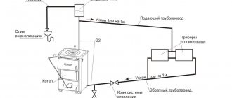
The natural circulation of water in heating systems operates due to gravity. How does this happen:
- Take an open vessel, fill it with water and start heating it. The most primitive option is a saucepan on a gas stove.
- The temperature of the lower layer of liquid increases, the density decreases. The water becomes lighter.
- Under the influence of gravity, the upper heavier layer sinks to the bottom, displacing less dense hot water. Natural circulation of liquid begins, called convection.
Reference. The dependence of water density on temperature is not linear. The more the liquid heats up, the faster its density decreases, which is clearly visible on the graph.
Example: if you heat 1 m³ of water from 50 to 70 degrees, it will become 10.26 kg lighter (see below for a table of densities at different temperatures). If we continue heating to 90 °C, then the cube of liquid will already lose 12.47 kg, although the temperature delta remains the same - 20 °C. Conclusion: the closer the water is to the boiling point, the more active the circulation occurs.
In a similar way, the coolant circulates by gravity through the home heating network. The water heated by the boiler loses weight and is pushed upward by the cooled coolant returning from the radiators. The flow speed at a temperature difference of 20–25 °C is only 0.1…0.25 m/s versus 0.7…1 m/s in modern pumping systems.
Low speed of fluid movement through pipelines and heating devices causes the following consequences:
- The batteries have time to give off more heat, and the coolant has time to cool by 20–30 °C. In a conventional heating network with a pump and a membrane expansion tank, the temperature drops by 10–15 degrees.
- Accordingly, the boiler must produce more thermal energy after the burner starts. It is pointless to keep the generator at a temperature of 40 °C - the flow will slow down to the limit, the batteries will become cold.
- To deliver the required amount of heat to the radiators, it is necessary to increase the flow area of the pipes.
- Fittings and fittings with high hydraulic resistance can worsen or even stop gravity flow. This includes check valves, three-way valves, sharp 90° turns and pipe reductions.
- The roughness of the internal walls of pipelines does not play a big role (within reasonable limits). Low fluid speed means low frictional resistance.
- A solid fuel boiler + gravity heating system can safely operate without a heat accumulator and a mixing unit. Due to the slow flow of water, condensation does not form in the firebox.
As you can see, there are positive and negative aspects in the convection movement of the coolant. The former should be used, the latter should be minimized.
Design features
For a gravity system to work effectively, the following requirements must be met:
- the heat source is any non-volatile heat generator with outlet pipes with a diameter of 40-50 mm;
- at the outlet of a boiler or stove with a water circuit, an accelerating riser is immediately installed - a vertical pipe through which the heated coolant rises;
- the riser ends with an open-type expansion tank installed in the attic or under the ceiling of the upper floor (depending on the type of wiring and the design of the private house);
- tank capacity – 10% of the coolant volume;
- by gravity, it is advisable to choose heating devices with large internal channels - cast iron, aluminum, bimetallic;
- for better heat transfer, heating radiators are connected according to a versatile pattern - bottom or diagonal;
- special full-bore valves with thermal heads (supply) and balancing valves (return) are installed on the radiator connections;
- It is better to equip batteries with manual air vents - Mayevsky taps;
- replenishment of the heating network is organized at the lowest point - near the boiler;
- all horizontal sections of pipes are laid with slopes, the minimum is 2 mm per linear meter, the average is 5 mm/1 m.
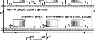
On the left in the photo is the coolant supply riser from a floor-standing boiler with a pump on the bypass, on the right is the return line connection
Note. Slopes perform 2 functions - they help the coolant flow in the desired direction, and the air rises through the pipelines and leaves through the open expansion tank. A caveat regarding the radiators used: if the system is built correctly, steel panels also heat well.
Gravity heating systems are made open and operated at atmospheric pressure. But will gravity flow work in a closed circuit with a membrane tank? We answer: yes, natural circulation will continue, but the speed of the coolant will decrease and efficiency will drop.
It is not difficult to substantiate the answer; it is enough to mention the change in the physical properties of liquids under excess pressure. With a pressure in the system of 1.5 Bar, the boiling point of water will shift to 110 °C, and its density will also increase. The circulation will slow down due to the small difference in the masses of the hot and cooled flow.
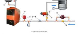
Simplified gravity flow diagrams with an open and membrane expansion tank
Heating systems with top water supply
The coolant - in this case water - is heated and supplied to the upper part of the heating system through a pipeline. The pipe used to supply water must have a larger diameter compared to the pipes that are responsible for supplying water to the radiator. This is necessary to achieve the greatest resistance to heat exchange. Horizontal pipes must be installed with a minimum slope of one centimeter per adjusted meter.
The expansion tank must be installed at the top of the system: it will perform the function of receiving steam and excess heat - this is necessary due to the property of water to expand when heated and turn into steam. The tank must have a drain valve and a cap or valve at the top. After the water is heated, it is distributed through the supply pipe to the vertical risers and into the radiators.
Tip: if you are going to use a heating system with natural circulation of water, remember that radiators must be connected using a diagonal method
After direct heating of the room, the water passes into the boiler through a specialized pipe - the return. Here it is heated again and the cycle of water movement is repeated. The heating boiler is located in the lowest part of the system, under the radiators. Typically, these elements are installed in boiler rooms, for which basements are allocated.
Calculation of gravity system
To calculate and design heating with natural circulation, proceed in this order:
- Find out the amount of heat needed to heat each room. Use our instructions for this.
- Choose a non-volatile boiler - gas or solid fuel.
- Develop a diagram based on one of the options proposed here. Divide the wiring into 2 branches - then the lines will not cross the front door of the house.
- Determine the coolant flow for each room and calculate the pipe diameters.
Note. There is no need to calculate slopes; take the standard value of 0.5 cm per meter of length. Deviations up or down in the range of 0.7…0.2 cm/1 m are allowed.
It will not be possible to split it into 2 branches right away. This means that the ring pipeline will definitely pass under the threshold of the front door. To withstand all the slopes, the boiler will have to be placed in a pit.
The calculation of the diameter of the pipes in all sections of the gravity two-pipe system is done as follows:
- We take the heat loss of the entire building (Q, W) and determine the mass flow rate of the coolant (G, kg/h) in the main line using the formula below. The temperature difference between supply and return Δt is taken equal to 25 °C. Then we convert kg/h to other units - tons per hour.
- Using the following formula, we find the cross-sectional area (F, m²) of the main riser, substituting the value of the natural circulation speed ʋ = 0.1 m/s. We recalculate the area of the circle into diameter, we get the size of the main pipe suitable for the boiler.
- We calculate the thermal load on each branch, repeat the calculations and find out the diameters of these lines.
- We move on to the next rooms and again determine the diameters of the sections based on heat costs.
- We select standard pipe sizes, rounding the resulting numbers up.
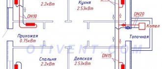
Let's give an example of calculating a gravity system in a one-story house of 100 square meters. The layout below already shows heating radiators and indicates heat losses. We start from the main boiler manifold and move towards the last rooms:
- The amount of heat loss at home is Q = 10.2 kW = 10200 W. Coolant flow in the main riser G = 0.86 x 10200 W / 25 °C = 350.88 kg/h or 0.351 t/h.
- The cross-sectional area of the supply pipe is F = 0.351 t/h / 3600 x 0.1 m/s = 0.00098 m², diameter d = 35 mm.
- The load on the right and left branches is 5480 and 4730 W, respectively. Amount of coolant: G1 = 0.86 x 5480 / 25 = 188.5 kg/h or 0.189 t/h, G2 = 0.86 x 4730 / 25 = 162.7 kg/h or 0.163 t/h.
- The cross section of the right branch is F1 = 0.189 / 3600 x 0.1 = 0.00053 m², the diameter will be 26 mm. Left branch: F2 = 0.163 / 3600 x 0.1 = 0.00045 m², d2 = 24 mm.
- Lines DN32 and DN25 mm (rounded up) will come to the nursery and kitchen. Now we calculate the sizes of collectors for the bedroom and living room + corridor with heat losses of 2.2 and 2.95 kW, respectively. We get both diameters DN20 mm.
To connect small batteries, you can use DN15 connections (outer d = 20 mm), the plan shows DN20 dimensions
Attention! The diameters obtained as a result of calculations indicate the size of the internal passage of pipelines (designation - DN or DN).
All that remains is to pick up the pipes. If you make heating from steel, the boiler riser will be Ø48 x 3.5, the branches will be Ø42 x 3 and 32 x 2.8 mm. The remaining wiring, including connections to the batteries, is done with a 26 x 2.5 mm pipeline. The first digit of the size indicates the outer diameter, the second - the wall thickness (range of water and gas steel pipes).
Selecting a circulation pump for a heating system
In order to select a circulation pump for the heating system, it is necessary to make the appropriate calculations. Please note that within an hour, this element will drive three times more water than its total volume in the system. Thus, the total volume of a suitable amount of liquid is on average 10 liters per 1 kilowatt of heating boiler power. The required pump model for the heating system and its power are determined by pressure and flow parameters. The pressure must be equal to the hydraulic resistance of the heating system.
Circulation pump
Typically, the fluid pressure velocity in systems with forced circulation is quite low, which gives the right to judge low losses of hydraulic resistance, which usually do not exceed 2 meters. It is quite difficult to calculate the exact resistance, so the performance of the circulation pump is determined by the midpoint. In order to calculate productivity, the size of the area of the heating object and the power of the electricity source are also taken into account. It should be remembered that a pump is only needed in a system with forced circulation; a system with natural circulation does not need it.
Do-it-yourself installation recommendations
To lay the main natural circulation lines, it is better to use polypropylene or steel pipes. The reason is the large diameter, polyethylene Ø40 mm and more is too expensive. We make radiator hoses from any convenient material.
Advice. When assembling a gravity heating network made of metal-plastic, do not install compression fittings - they greatly reduce the internal passage.
An example of installing a two-pipe wiring in a garage.
How to make the wiring correctly and withstand all slopes:
- Start with markings. Mark the locations for installing batteries, connection points for connections, and routes for highways.
- Mark the routes on the walls with a pencil, starting from the distant batteries. Adjust the amount of inclination using a long building level.
- Move from the outer radiators to the boiler room. When you draw all the routes, you will understand at what level to install the heat generator. The inlet pipe of the unit (for cooled coolant) must be located at the same level or below the return line.
- If the firebox floor level is too high, try moving all the heaters up. Horizontal pipelines will rise next. As a last resort, make a recess under the boiler.
Laying a return line in a furnace room with a parallel connection to two boilers.
After marking, punch holes in the partitions and cut grooves for a hidden gasket. Then check the routes again, make adjustments and proceed with installation. Follow the same order: first secure the batteries, then lay the pipes towards the combustion chamber. Install an expansion tank with a drain pipe.
The gravity pipeline network is filled without problems; Mayevsky’s taps do not need to be touched. Just slowly pump water through the fill valve at the lowest point, all the air will go into the open tank. If any radiator remains cold after warming up, use a manual air vent.