The heating system consists of sections of pipes connected to each other. The coolant moves through them. In order to shut it off or adjust the pressure, a needle tap is used. With its help, not only the liquid, but also the gaseous medium is blocked. Unlike a ball device, the main part of a needle valve is a rod, which looks like a narrow needle. Due to the movement of the conical part, the pressure of the moving medium is regulated.
Device and scope
A needle valve consists of a number of elements. The structure includes:
- The body with the parts placed in it.
- Lever. When it rotates, the rod makes reciprocating movements.
- Rod with spindle. With the help of these elements, the coolant supply is shut off.
- Locking screw. Provides fastening of the device to the pipeline.
- Stuffing box. Inserted into the gap between the body and the rod, it prevents water from escaping.
- Oil seal nut.
- Oil seal cover.
When the handle is rotated clockwise, the rod moves downward along the thread and closes the conical part of the hole through which water or gas passes. The material of the main parts is stainless steel, which prevents corrosion upon contact with the active medium.
The device got its name because of the needle shutter. The main parts are manufactured using high-precision equipment. There is a special requirement for their quality, since they need to withstand high pressure of liquid or gas.
The work takes place both in conditions of high temperatures - +560 degrees, and low temperatures - -60 degrees.
The shut-off needle valve is used in various systems. It is especially necessary in cases:
- Settings in front of the pressure gauge. This device often requires maintenance; it is used to monitor the pressure in the system. Replacement or maintenance of the pressure gauge requires preliminary dismantling. To do this, the moving flow is blocked by a valve for the period of repair of the element.
- Use of the device in systems with high pressure up to 40 mPa. The device is able to withstand such a load, because when it is smoothly closed, large pressure fluctuations are not created.
- Installation in a heating system and use for air bleed.
- Applications in automobile carburetors.
- Installations for water distillers.
Characteristics
How to choose a three-way tap for heating
There are such features of the shut-off and control device:
- control is carried out manually;
- connection to the auxiliary pipeline of the heating system is made using flanges;
- the pressure gauge is connected using couplings;
- the possibility of shutting off the needle valve if fragile elements of the pressure gauge are destroyed (under the influence of high pressure).
Basically, a needle valve is used to regulate the flow of the working medium with your own hands, which can include any type of coolant in the heating system. In addition, it has three positions: closed, partially open and fully open.
Types of designs
Depending on the purpose and design features, needle valves have many varieties. According to their purpose, they are divided into the following types:
- Locking. Used for large-scale highways. Their function is to completely block the moving flow. They are installed on high pressure pipelines. The disadvantages include a short service life.
- Regulatory. They are built into a system with a liquid medium to regulate the moving flow, change its volume or pressure.
- Balancing. They are built into heating systems; with their help, it is possible to redirect liquid to another channel without changing the parameters of pressure, temperature and volume.
There are also significant differences depending on the type of design. Here the valves are divided into the following:
- Walkthroughs. They differ in their dimensions. Installation is carried out at the junction of the pipes. The disadvantages include the likelihood of rapid clogging, which makes it necessary to disassemble and clean them.
- Angular. Installation is carried out at corner joints of pipes. The variety has a wide range of sizes.
- Straight-through. They are mostly used for pipelines with petroleum products, so they are not popular in domestic conditions. Advantages include less chance of clogging.
An important factor is to ensure tightness in the system. According to this characteristic, valves are:
- Salnikov. Ensures tightness of the housing at any position of the rod. The disadvantage is the low reliability of the design.
- Bellows. The sealing layer is vacuum. This design is more solid, so it is installed in systems with high pressure.
Types of needle valves
Valves of this type differ in several parameters. There are three types of devices according to their purpose:
- constipation;
- regulatory;
- balancing
Shut-off valves are capable of completely shutting off the flow. They are most resistant to high pressure and temperature, but their service life is short. Liquids and gases often enter such valves, leading to metal corrosion. Shut-off valves are used on large highways.
Control needle valves are used if it is necessary to change the properties of the internal working environment. For example, reduce pressure or volume. Their area of application is small diameter pipelines with liquid media.
Balancing valves are designed to regulate hydraulic resistance. In other words, they redirect the flow of liquids from one pipe to another, allowing the balance of volume, pressure, speed or temperature to be maintained at a given level. They are often installed on heating systems.
The valves are classified according to their design features:
- checkpoints;
- corner;
- direct flow
Continuous valves are installed on pipelines at points where pipes are directly connected. They are characterized by relatively large dimensions compared to the size of the pipe. Due to the design features, stagnation often occurs in such mechanisms; they must be cleaned periodically.
Angle valves are used where pipes are located at an angle to each other. For example, if the pipeline turns to form an elbow. An angular needle valve is installed at the turning point. They come in different diameters and are designed for systems with any internal environment.
Direct-flow structures are distinguished by their relatively large length and weight. They have not found widespread use in everyday life, despite a number of advantages, including a reduced possibility of stagnation inside the mechanism. They are used as control valves in oil pipelines.
According to the method of ensuring the tightness of the system:
- stuffing box;
- bellows.
One of the elements of a stuffing box valve is a seal that prevents the working medium from escaping outside, regardless of the position of the stem. This option is not always reliable in terms of tightness.
We recommend that you read: How to choose and install a faucet for a radiator of a heating system?
Bellows valves use vacuum as a sealing medium. Vacuum seals are often used in high pressure systems. They are more reliable and leak less often.
Advantages and disadvantages
Despite the wide variety of products, they have their own advantages and disadvantages. The positive aspects include:
- Uninterrupted operation under conditions of significant temperature changes.
- Possibility of installation in places of high pressure where it is impossible to install another shut-off element.
- Simplicity of design, which makes installation and further maintenance possible with your own hands.
- Corrosion resistance.
- Long service life - 15 years.
- Ability to smoothly shut off flow. This is especially important on high-pressure pipelines to avoid creating voltage surges that lead to a system breakthrough.
- Reliable sealing. It is ensured by good overlap of the bore rod.
In addition to the advantages, needle taps also have disadvantages. These include:
- High resistance of the device, leading to loss of energy. It is easier for the coolant to pass through a flat section of pipe than a valve mechanism.
- Inability to work with viscous media at high pressure.
- Long mechanism length. This negatively affects the overall operation of the system.
- The need for periodic cleaning.
- The likelihood of a complete replacement of the mechanism in case of breakdown.
- Unidirectional coolant movement.
Installation of a tap in a heating system
As a rule, a faucet with flanges is installed in the heating system. This method is simpler.
To perform installation you need:
- choose a place;
- seal the valve thread using FUM tape;
- tighten the structure;
- check for leaks.
Installation of a tap in a heating system
Before starting work, you need to remove the coolant from the system. If there is an autonomous system, then there will be no problems. For residents of apartment buildings, this process should be coordinated with the service company.
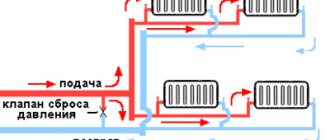
The fittings are installed in front of the heating device or behind the bypass, which serves for continuous circulation of water after shutting off. If there is no bypass pipeline, then it is installed.
When installing the crane, take into account:
- ensure unhindered rotation of the adjustment knob;
- provide free access to the valve.
Before purchasing a valve, you should make sure that the diameters of the pipe and the device match, as well as the type of thread. For flange connections, the following elements are:
- two internal threads;
- two external threads;
- two types of threads are on different sides.
Flange-type faucets have an arrow indicating the direction of water movement. It is also necessary to wind the seal correctly. If the thread on the pipe is open, then the FUM tape is wound while facing the pipe clockwise. If there is an open thread on the flange, the operation is performed in the same way, but you need to be facing the valve. Next, efforts are made to tighten the thread.
After finishing the work, everything is checked for leaks. The system is filled with water at high pressure. The cause of the leak is insufficient sealing.
Selection rules
Before choosing one or another type of device, you need to have a good idea of why it is being purchased, what functions it will need to perform and how to secure it.
Since the product is made from different materials, it is necessary to consider the conditions in which it will work. Cast iron is suitable for home heating. In apartment conditions there is no high pressure, and the liquid is not aggressive, so the product can last at least 15 years.
If the coolant is aggressive (chemically active substances), then the taps are selected from stainless steel or brass. Such products are installed in large heating plants.
It is important to pay attention to the mounting methods. They are:
- threaded;
- coupling;
- flanged;
- welded.
The first 2 options are optimal for home conditions. The other two are even more reliable and can withstand a pressure of 15 MPa. However, their use in the private sector is impractical, since they are intended for use at large facilities.
Types of water regulators
According to the capacity of the relay, it can be domestic (0.5-3 m3), commercial (3-15 m3) or industrial (over 15 m3). For greater efficiency, the element is used in conjunction with pressure gauges, coarse filters, shut-off valves and ball valves. The main difference between water pressure regulators in a water supply system lies in the design features.
Piston
The composition contains a characteristic element - a piston. It survives, and in the blocked position completely closes the inlet (outlet) holes. The operating principle of a piston-type pressure regulator is that when the pressure changes, the piston stabilizes this parameter automatically. There is a valve for adjustment. It is used to configure and test functionality.
Membrane
The locking element is a spring-loaded membrane installed in a special sealed chamber. After it is triggered, the force is transferred to the valve, which shuts off the flow. The complex device makes products of this type more expensive compared to piston ones. The membrane can be damaged not only by the rod and spring, but also by rust. To prevent this from happening, you need to install a coarse filter or a shut-off valve with a strainer at the inlet.
Flow-through
The essence of the work is that the incoming flow is divided into several small ones, which rush through special channels. Then they merge together, forming a new one, but not as powerful. Plus - the absence of mechanical components, and as a result, durability. The downside is a lower degree of control, and in some cases it is necessary to install an additional water reducer.
Automatic
There is also a membrane here, but there are already two springs. The essence of the work is that when the pressure in the automatic regulator drops, it weakens, and when it increases, the pressure increases. This mechanical action makes or opens contacts. As a result, the circulation pump is turned on or off. The device is applicable in forced water supply systems.
Electronic
The main difference is the fluid movement sensor. The device is controlled by a digital block that determines when to turn on the pump. All information about operating parameters is displayed on the display. Nearby are the control buttons. The purpose of the device is not only to protect the system from surges, but also to maintain constant pressure in the system. The only drawback of such devices is the price due to the complexity of the device.
Features and principles of operation
The needle shut-off valve gets its name from the design feature of the working part of the locking rod. It has a conical shape, resembling a needle in appearance. Otherwise, its configuration and operating principle are no different from its analogues.
The needle shut-off valve consists of:
- housings (steel, nickel-plated steel, brass, copper and other metals);
- a rotary handle, with the help of which the locking mechanism is driven;
- rod with conical locking spindle;
- seal;
- nuts and oil seal covers;
- casing;
- set screw.
When the rotary handle rotates, the rod moves smoothly down the seat, blocking the flow.
Needle valve device (inside view)
When rotating in the opposite direction, the spindle rises upward, opening a passage for the working medium of the pipeline. Thanks to the conical shape of the rod, very smooth adjustment of the flow of the working medium is possible.
There are designs of these shut-off valves with manual adjustment and with electric drives.
Application area
The needle shut-off valve has a very wide range of applications. It can be used to regulate the working environment of pipelines transporting liquids, gases, steam, food and chemicals.
They are used in the installation of high and low pressure pipelines, in industries and in everyday life. Needle valves type 15s54bk (vi) and VT-5 are indispensable in vehicle systems, in particular in gas-cylinder equipment, since they allow very precise adjustment of the fuel supply. Products with a diameter of DN6 - DN15 are suitable here.
Needle shut-off valves marked VI and VT are often installed on low pressure systems up to 10 MPa. However, more often these shut-off valves are considered high-pressure valves.
Needle valves are used for high and low pressure systems
Stainless steel shut-off needle valve 15s54bk (VI) and VT-5 can be installed on high-pressure pipelines from DU6, DU10, DU15 to pipes with a diameter of 65 mm. In addition, models 15s54bk (VI) and VT-5 operate under pressure conditions of up to 40 MPa and perform their functions at operating temperatures from -40 to +200ºC.
The 15s54bk needle shut-off valve can be used in a high-pressure pipeline system under conditions of a homogeneous, non-viscous flowing medium.
Where is a needle valve indispensable?
There are two cases when it is worth installing exclusively a 15s54bk (VI) or VT-5 needle locking mechanism into a pipeline system. An attempt to replace it with any other equipment would be extremely irrational.
- A needle shut-off valve is always installed in front of the pressure gauge so that the measuring device can be disconnected from the system for cleaning and purging. In addition, this shut-off valve automatically shuts off the flow in the event of a rupture of pressure gauge elements.
- A needle shut-off valve is installed in a high-pressure pipeline system, especially on long main runs. In this case, equipment of type 15s54bk (VI) or VT-5 is generally irreplaceable, since any shut-off mechanism that suddenly blocks the flow can lead to water hammer and rupture of the pipeline. On high-pressure lines up to 15 MPa, it is very important to smoothly stop the movement of the working medium.
Types and designs
Valves differ in the direction of flow: there are straight-through, angular and through (with a displacement of the water flow at the inlet relative to the outlet).
Depending on the method of sealing the spindle (stem), valves are of the following types:
stuffing box The most common type. On the outside of the housing, at the point where the spindle passes, a stuffing box is created, filled with stuffing box made of sealing material;
bellows. The bellows is made from a corrugated pipe welded to the upper and lower rings. The bellows assembly is fixedly connected by the upper ring to the valve body, and by the lower ring to the rod (or valve spool). The rod moves inside the bellows, while the corrugated pipe compresses and decompresses. Such a unit has better sealing than a stuffing box unit and is used when working with toxic and aggressive media. Disadvantages: design complexity and high cost;
membrane fittings - the seal is made in the form of a membrane, the central part can bend with an amplitude sufficient to close/open the shut-off element. Disadvantages: short service life, low operating pressure and temperature.
Features of installation and operation
- The valve can be installed in a vertical or horizontal position.
- First of all, the half-grip pipe is connected to the system (before installing it, the integrity of the O-ring is checked). Coupled manual valves for radiators are installed with the mandatory use of fluoroplastic seals. Installation and fastening of the pipe is possible using a special wrench. (The use of lever wrenches is strictly prohibited.)
- Before disassembling the shut-off and control manual valve, the coolant is drained.
- Before installation and operation, you must familiarize yourself with the rules for using the fittings, because Each type of device has special technical limitations and features.
In any modern apartment or private house, the heating system plays an important role. And today there are a sufficient number of functional devices and solutions that make it much more energy efficient and adjustable. After all, it’s no secret that heating in our homes does not always work as we would like.
In this material we will look at why control valves for heating radiators are needed and how they will help improve the heating of a house or apartment.
So, radiator valves (valves) are a type of pipeline shut-off and control valves. And they are designed to regulate (control) the coolant flow in the radiator in manual mode. Depending on the design, straight and angular ones are distinguished. Most often they are made from brass or bronze. As a rule, valves are distinguished by their low price, tightness and often stylish design.
Unlike conventional ball valves (shut-off type), a manual regulating valve for radiators allows you to more smoothly change the amount of coolant, i.e. liquids into batteries. This means that at any time you can adjust the temperature in the room as you wish. For example, if the room is already warm, then the heating is clearly excessive, then using a valve you can reduce the heat transfer from the radiator. But it is worth remembering that an angle valve for a radiator can only reduce the heat transfer of the battery!
Types of mixers and their design
Of the entire range of commercially available mixers, the following main types stand out:
- with two levers;
- with one lever;
- mixers with thermostat;
- touch-controlled faucets - this category also includes smart faucets that are controlled using a display.
Many bathrooms and kitchens still retain the “classics” of the domestic “faucet industry” - two-valve faucets. Indeed, for a long period people simply had no other options. Such devices simply separated the flow of cold and hot water.
Somewhat later, another know-how was invented, or, to be more precise, a mixer with one lever. By moving the mixer lever up or down, you could control the pressure of the water flow, and by turning it left or right, you could switch to cold or hot water. The type of mixer, familiar from Soviet times, is gradually fading into oblivion.
Designers are trying to come up with something new, striving for a more modern appearance of plumbing fixtures. From a practical point of view, this approach has only brought benefits. Now you can adjust the device much faster, and it’s easier to control.
Devices with two valves are divided into two subtypes. The first includes an option in which the locking role is played by a gasket made of elastic material. The reciprocating type cartridge can open and close the passage of water. It is silicone gaskets that extend the life of such a device. The second subtype of mixers includes those in which a pair of ceramic plates serve as a locking element. The plate mounted on top can rotate, while the bottom one is fixed. This type of mixer is much more expensive than the first one.
Single lever mixer
There are a lot of different holes on the body of a device with one lever; they are needed for tubes and mounting elements. The spout of such a mixer can be either movable or made as a single unit with the body. Monolithic with a body is most often found in mixers in which the handle is installed in the upper part. If the lever is mounted at the bottom, then the spout is usually very long and high. Modern single-lever taps are equipped with aerators, which not only fill the water flow with oxygen, but also significantly reduce water consumption.
In faucets with one ball-type lever, a rounded part is located in the central part. There is a cavity inside, as well as three holes. Smooth operation and durability are ensured by a rubber seat. This element is secured with retaining rings. The mixer lever, when returned to its original position, comes into contact with the stem. When you turn the lever, the flows of cold and hot water are combined into one. If the lever is lowered, the water is shut off.
Mixer with thermostat
One of the modern models. Thanks to the built-in thermostat, the water coming from the tap always has the same temperature. The thermostat itself is hidden inside the faucet box. There are two handles to control the water flow. One of them regulates the water pressure, and the second regulates its temperature. This design of the device allows you to satisfy the needs of a larger number of users.
Faucets of this type are mounted either on walls or on washbasins. As a rule, the kit includes elements that limit the maximum water temperature. If something small breaks in such a device, then you can correct the situation on your own. Leave larger troubles to the specialists.
Touchless faucets
All devices where water is supplied automatically are called non-contact or, in other words, touch devices. By placing your hand near the sensor, you can activate the water supply. Thanks to this device, the time and effort required to perform simple actions is reduced.
In addition to the usual ones with sensors, there are also smart faucets. In terms of various built-in functions, they are clearly in the lead. The basic delivery of touch models consists of a one-piece body with a spout, a battery, and an electronic control unit.
Similar names:
- The mixer is automatic.
- Infrared mixer.
The sensors themselves, which are installed on such mixers, can be not only of the infrared type. Touch-controlled devices use water wisely. Perhaps some people will not like this - those who prefer to turn on the water pressure more strongly. But the fact that they have increased hygiene is definitely liked by all users. They very rarely fail and almost never get dirty. And it will certainly be difficult to create a lake in the bathroom with such faucets.
How to set up the regulator yourself?
The operating principle of the devices is the same, but the regulators are different in design.
There are also differences in the design of the adjusting screws. You may need various tools to rotate them.
For more precise adjustments, you can use a pressure gauge. Some devices have special threaded places for their connection.
Preparation
Depending on the design of the adjusting screw, you may need:
- 4 or 6 mm hexagon;
- standard screwdriver with a flat wide blade;
- a special key or a steel strip about 2 mm thick and up to 20 mm wide.
To visually monitor the pressure at the outlet after the reducer, you may need a pressure gauge with an adapter to connect to the shower hose or faucet connector.
The regulator is adjusted at the minimum possible water flow through one water tap.
Settings
To set up the pressure regulator in the apartment’s water supply system, perform the following steps:
- turn off all taps on the internal water supply;
- install a pressure gauge on the gearbox or connect it to the internal water supply;
- open 1 tap so that the water flow is minimal, that is, a thin stream that does not break up into separate drops;
- visually determine the pressure in the water supply using a pressure gauge before starting the adjustment;
- remove the plug from the hole in the housing where the adjusting screw is installed;
- insert the tool into a screw suitable for the configuration;
- to increase the pressure, it is necessary to rotate the screw counterclockwise, the spring load on the valve will decrease, and the valve will close at higher pressure;
- to reduce the pressure, rotate the screw clockwise, the spring load on the valve will increase, and the valve will close at lower pressure;
- make a trial use of tap water to check the comfort of using water;
- if necessary, adjust the setting;
- close the plug of the hole plug on the gearbox, disconnect the pressure gauge.
Some models have a rotation head for the adjusting screw and may even have a scale indicating conventional values.
You can adjust the pressure in the water supply without a pressure gauge. To do this, after each full turn of the adjusting screw, you should check the pressure from the water tap, including the impact of the jet on the palms.
One turn of the screw changes the value by approximately 0.5 - 1.0 bar. For more precise adjustment, at the end of the adjustment, make half a turn of the screw.
This method may turn out to be even more acceptable, because the pressure is adjusted, first of all, for comfortable use of water, including when washing hands.
Types of regulators
According to the principle of operation, RVDs can be piston, membrane, flow, automatic and electronic.
Piston
Water pressure valves are the simplest in design (they are also called mechanical). Pressure adjustment is carried out by a compact spring-loaded piston by reducing or increasing the passage channel. To adjust the outgoing water pressure, the device has a special valve: by rotating it, you can loosen or compress the spring.
The weaknesses of piston regulators include their sensitivity to the presence of debris in the water: piston clogging is the main cause of breakdowns. To prevent such phenomena, a special filter is usually included in the gearbox kit. Another drawback is the large number of moving mechanical components, which affects the reliability of the gearbox. The piston device is capable of regulating pressure in the 1-5 atm mode.
Membrane
Very reliable and unpretentious devices that make it possible to adjust the water pressure over a wide range (0.5-3 m3/hour). For living conditions this is a very decent indicator.
The core of the device is a spring-loaded membrane: to avoid clogging, a self-contained sealed chamber is used to install it. The impact from the compressing or expanding spring is transferred to a small valve, which is responsible for the size of the cross-section of the output channel. The cost of membrane restrictors is quite high. Due to the difficulty of replacement, this procedure is usually performed by experienced plumbers.
Flow-through
A special feature of this model of water pressure regulators is that it completely lacks moving elements. This has a beneficial effect on the reliability and service life of the devices.
The pressure is reduced due to the intricacy of narrow channels. When passing numerous turns, the water is divided into separate branches, at the end merging again into one, but not so fast. In domestic use, flow reducers can be found in irrigation systems. The disadvantage of the device is the need for an additional regulator at the output.
Automatic
A small unit consisting of a membrane and a pair of springs. To change the compression force, special nuts are used. When the inlet water has low pressure, this leads to a weakening of the membrane. Increased pressure in the pipe provokes an increase in compression.
Under the influence of the spring, the contacts on the automatic pressure reducer either open or close again. This, in turn, turns the circulation pump of the forced water supply system on and off. The design of automatic high-pressure pumps basically duplicates membrane devices, differing only in the presence of two correction screws for setting the operating pressure range.
Electronic
A special mechanism monitors the water pressure in the pipe, for which a motion sensor is used. After processing the received data, a decision is made to turn on the pumping station. The electronic regulator will block the pump from turning on if the pipeline is not filled with water. The design includes the main body, sensors, an electronic circuit board, a connecting sleeve (thanks to which the supply wire is turned on) and threaded pipes for connecting to the system.
The stabilizer design has a convenient display to display the characteristics of the water flow. Mechanical regulators are sometimes unable to effectively protect the system from dry running, which is why it is necessary to constantly monitor it for the presence of water. In contrast, electronic models with a controller are able to constantly monitor water filling. Gearboxes of this type operate almost silently, reliably protecting all components from hydraulic shocks.
Read with this
- Hydraulic accumulator selection and principle of operation
- Reducer or water pressure regulator in the water supply system for home and apartment
- Features of analyzing water from a well: when is it necessary and what is the cost?
- Pumping station for increasing water pressure: features of selection and installation in an apartment and house
- Why the water station does not gain pressure: the main reasons
- How to make water filters with your own hands?
- Subtleties of the faucet replacement process
- Dry running sensor for pump
- Toilet flush cistern
- Manufacturing and connecting a sauna stove with a water heat exchanger