Solid fuel boilers, due to their versatility, are popular among owners of private houses. An efficient and easy-to-use mine boiler not only allows you to quickly heat a room, but also operates for as long as possible with one load of fuel. Such installations will differ in their design, size, power and a number of other parameters.
Heat your private home with a pyrolysis boiler
Description of equipment
Long-burning mine boilers are an effective technology that is characterized by the longest possible fuel burning time and unique design features. The presence of a fuel chamber with increased dimensions eliminates the need for frequent loading, and thanks to the special design of the blower, slow combustion is ensured with the release of a large amount of heat.
The most widespread today are two designs of mine boilers:
- Pyrolysis.
- With normal combustion.
Both of these designs have two chambers, one of which contains a heat exchanger, and the second is used for burning fuel. The shaft-type boiler with bottom combustion is characterized by a simple design and has a firebox as high as the entire unit, which makes loading significantly easier. The combustion chamber resembles a shaft in appearance, which served as the name for heating equipment of this type.
In this video we will look at a mine boiler:
The heat exchanger chamber is made using classic fire tube technology. Inside this compartment there are numerous pipes through which a heat exchanger circulates, heated by hot air coming from the firebox. The chimney can be made either in the form of a vertical pipe or a coaxial type, which is discharged through the nearest wall to the street.
Mine boilers for long-term bottom burning with wood received a modified design, which made it possible to ensure the longest possible combustion. This boiler is supplemented with the following elements:
- In additional chambers located under the heat exchanger, carbon monoxide is burned, which improves the efficiency of the boiler.
- Pipes with numerous small holes are installed in the pyrolysis chamber, which allows the supply of air necessary for the combustion of carbon monoxide.
- Directly above the pyrolysis chamber there is a valve, which allows you to reduce and increase the intensity of fuel combustion.
The operating principle of such a pyrolysis mine boiler is based on limiting the flow of air into the combustion chamber. Accordingly, wood burns extremely slowly, which leads to the formation of large amounts of carbon monoxide. This design allows for equipment efficiency of 90%.
Mine type
They are distinguished by their considerable height (can reach one and a half meters).
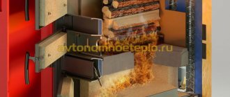
The firewood is stacked to its full height, ignited from below, where the combustion process occurs, and the flame torch is directed to another section, connected at the bottom to the main boiler.
The combustion products, passing further through the heat exchanger, cool and are removed into the pipe.
This boiler design allows the use of pyrolysis combustion. To do this, a damper is installed that limits the air supply and is connected to a draft and temperature sensor. And in the second chamber, when air enters, combustion of the released gases occurs.
Mine-type boilers cope well with wet firewood and sawdust. We can say that this is an ideal option for wet firewood.
Procedure for assembling a shaft-type boiler, step by step
Suitable for manufacturing is steel with a thickness of at least 4 mm, preferably heat-resistant.
Elements of the inner side of the firebox and heat exchanger are installed on the base and secured in several places. Then the back wall and supports for the grate are installed. The diagonals are carefully checked, and only after that the parts are finally welded. After this, the heat exchanger pipes are installed.
Drawing of a shaft-type boiler with measurements
The next step is to assemble the outer side of the boiler, which is both the water jacket and the lining. The outer side is welded in a circle through spacer studs, so as not to swell and wave.
The chimney is led out through the rear wall so that a door can be installed on top for cleaning the second chamber. In total, there are three doors:
- Ash pan, for cleaning slag ash and providing air access.
- Furnace room, for loading firewood and sawdust (more convenient from above).
- For cleaning the second chamber and replacing the brick (top).
The secondary chamber is sometimes lined with brick; it heats up and helps burn off the gases coming from the firebox.
It is also important to consider:
- Incorrect design will result in the unit smoking when adding firewood.
- This design is more suitable for installation in a boiler room separated from the living space.
- Since firewood must sink under its own weight as it burns, it is important to stack it correctly. Otherwise the combustion stops.
- If you plan to use sawdust, then you need to load it on top of the burning firewood (and it is advisable that the sawdust be dried). But coal is extreme for this model.
- In all seams and joints, the metal is applied with an allowance of 5 mm. This allows for better welding of the part on both sides.
- At the end of the work, you can go over all seams with welding sealant.
If you install a mine boiler that is too powerful, you will have to limit the combustion force by cutting off the air supply, and this will lead to the formation of a large amount of condensation, which makes it difficult to clean the internal surfaces and reduces the service life of the iron.
Advantages and disadvantages
Due to their excellent performance characteristics and ease of use, mine boilers are popular among domestic owners of private houses. The main advantages of such units include the following:
- Simplicity of design.
- Long-term operation on one load of fuel.
- Excellent efficiency.
- Possibility of loading various solid fuels.
- Complete safety of operation.
- Ease of maintenance.
- Affordable price.
- Possibility of choosing units with different power.
The disadvantages include a bulky design with an enlarged combustion chamber, which leads to the need to install such equipment in a separate boiler room, where pipes and a full-size chimney are supplied.
By correctly choosing the design, power and dimensions of the fuel compartment, you can not only heat your house effectively, but also significantly simplify the maintenance of the boiler, which will be distinguished by the reliability and trouble-free operation of the equipment.
Heating boiler power - theory and real facts
A heating device operating on coal, wood or other organic fuel performs a certain job related to heating the coolant. The amount of work of boiler equipment is determined by the volume of heat load that a solid fuel boiler can withstand when burning a certain amount of fuel. The ratio of the amount of fuel consumed, the amount of thermal energy released at optimal operating modes of the equipment is the boiler power.
A heating unit that is incorrectly selected for power will not be able to provide the required boiler water temperature in the heating circuit. Low-power solid fuel devices will not allow the autonomous system to fully meet your needs in terms of heating your home and ensuring the operation of the hot water supply. There will be a need to increase the power of the autonomous device. A powerful device, on the contrary, will create problems during operation. It will be necessary to make design changes to the existing heating complex to reduce the thermal load of the solid fuel heating device. Why waste precious fuel if there is no need for so much heat.
For reference: if the boiler power exceeds the technological parameters of the heating system, the coolant in the circuit will disperse impulsively. Frequent switching on and off of the heating unit leads to excessive fuel consumption and a decrease in the operational capabilities of heating equipment in general.
From a theoretical point of view, calculating the optimal operating mode of boiler equipment is not difficult. It is generally accepted that 10 kW is enough to heat a living space of 10 m2. This indicator is taken taking into account the high thermal efficiency of the building and standard design features of the building (ceiling height, glazing area).
In theory, the calculation is made based on the following parameters:
- area of the heated room;
- specific power of heating equipment for heating is 10 kW. m, taking into account the climatic conditions of your region.
The table shows the average parameters of boiler equipment used by consumers in the Moscow region:
| Area of a residential building, other premises, m2 | Recommended unit power, kW |
| 60 — 200 | up to 25 |
| 200 — 300 | 25 — 35 |
| 300 — 600 | 35 — 60 |
| 600 — 1200 | 60 — 100 |
The thermal load parameters look optimal on paper, in theory, which is clearly not enough in relation to local conditions. The selected unit in reality should have redundant capabilities. In reality, you need to focus on equipment that can operate with a small power reserve.
Note: Excessive power of a solid fuel boiler will allow the entire heating system in the house to quickly reach optimal operating conditions. The additional resource should exceed the calculated data by 20-30%.
The actual load indicators of solid fuel units depend on a combination of various factors. The climatic conditions of the region in which you live may make adjustments when choosing a heating boiler. For the middle zone, the following power parameters of boiler equipment are considered optimal:
- one-room city apartment - boiler with an output load of 4.16-5 kW;
- for a two-room apartment - equipment rated at 5.85-6 kW;
- for a three-room apartment it will be enough to have a unit of 8.71-10 kW;
- a four-room apartment or a private residential house will require a boiler with parameters of 12-24 kW for heating.
Important! When it comes to installing solid fuel boiler equipment in private homes and suburban residential buildings, it is necessary to focus on devices with greater technological capabilities. To heat and provide hot water supply to a residential building with an area of 150 m2 or more, you will need to install a solid fuel boiler of 24 kW or more. It all depends on the intensity of the heating system and the volume of domestic needs for hot water.
It is always necessary to choose heating equipment individually, based on calculated data and your own needs.
Manufacturing of a mine pyrolysis boiler
The most popular today are the improved designs of pyrolysis boilers, which have high efficiency, save fuel, and can operate on one load for 24 hours or more, providing high-quality heating of the room. Due to the simplicity of the design of such an installation, it can be made independently, even with minimal experience in welding.
Required tools and materials
If you have a diagram for manufacturing a mine pyrolysis boiler on hand, it will not be difficult to complete it. This work does not require the use of any complex professional equipment; you can get by with the following tools and materials:
- Gas cutter.
- Welding machine.
- Various carpentry tools.
- Sheet steel 5 and 2 millimeters thick.
- Pipes of various diameters.
- High temperature fireclay brick.
- Corners 4 by 4 centimeters.
- Double ash door with asbestos gasket and valve for adjusting the air supply.
- Three valves that are necessary for the chimney and partitions between the chambers.
- Doors for servicing the heat exchange chamber.
- Galvanized steel sheet.
- Basalt wool.
A prerequisite for the production of a high-quality solid fuel mine boiler will be the availability of the appropriate manufacturing scheme for such equipment. You can make a drawing yourself, but it’s easier to find it in open sources on the Internet. Subsequently, all work, in particular metal cutting, is carried out on the basis of existing drawings and documentation.
When choosing a specific boiler manufacturing drawing, you should pay attention to the volume of the combustion chamber. The larger it is, the longer the bottom combustion mine boiler will operate on one refill. It is possible to manufacture such equipment, the size of the combustion chamber of which will allow the boiler to heat the room for two to three days, which greatly simplifies the maintenance of equipment and living in a private house.
Execution of the main part
The main part of the boiler is usually understood as a homemade body, which is divided into several chambers. Between them there are partitions and valves, which allow you to regulate the volume of air entering the combustion chamber . The body is made as follows:
- They study the drawing and determine the dimensions and method of cutting the sheet metal.
- Using a lining, a cutting pattern is made on a sheet of metal and the sheet steel is cut using autogenous welding or a plasma cutter.
- The side parts of the body are welded with a double seam.
- Two holes are made in the partition between the heat exchange and fuel chambers, one of which is located at the top, and the second at the level of the grate.
- The combustion chamber blank is installed in the body and secured by welding. A valve is attached to the upper hole of the partition and the base is welded.
Create a warm atmosphere in your home with pyrolysis boilers
- A grate is made by cutting narrow longitudinal holes in sheet steel using a lining. You can use a purchased cast iron or steel grate, which will somewhat simplify making a boiler with your own hands.
- The grate is welded or installed on the corners.
- The necessary holes are cut out in the side walls, which will be required for the combustion chamber doors and ash pan.
- Two rows of profile pipes or corners are welded inside the thermal chamber. Subsequently, elements of a water jacket will be attached to them; it is not recommended to place it inside the pyrolysis chamber, as this may disrupt the process of afterburning of gases.
- A heat exchanger is installed and welded into the housing, inside of which there is a water jacket. It is made from pipes with a diameter of 2.5 centimeters.
- At the level of the grate, a partition is welded, which serves as the bottom of the fuel afterburning chamber.
- A hole is cut out in the bottom part, which will be required for the air supply pipe.
- To supply air to the pyrolysis chamber, a pipe with a diameter of 5 centimeters is used, in which a large number of small holes are drilled. A blind valve is welded at the end of the pipe.
- The walls of the combustion chamber are lined with fireclay bricks. If necessary, it is trimmed, after which, using a high-temperature solution, masonry is carried out.
- Additionally, brickwork can be insulated with basalt wool, which improves the thermal efficiency of the equipment.
This completes the production of the main part. All that remains is to construct a heat exchanger, inside which a liquid will circulate, heated by hot gases and subsequently releasing heat through radiators installed in the house.
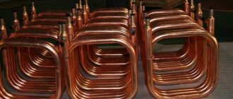
Heat exchanger assembly
The heat exchanger, or, as it is also called in another way, a water jacket, includes several rows of horizontal pipes. You can purchase ready-made options in specialized stores that sell spare parts for heating equipment. If necessary, you can make a high-quality and durable heat exchanger with your own hands or use an old one. done as follows:
- In accordance with the diagram available on hand, a rectangular or square shell is welded. Its width and depth should be approximately 6 centimeters less than the dimensions of the heat exchange chamber.
- Two holes are cut in the shell, coinciding with the location of the valve in the boiler partition and with the hole for cleaning the pyrolysis chamber.
- Holes for a pipe with a diameter of 2.5 centimeters are drilled on opposite sides of the shell. For this work, use a drill with a diamond bit or a special metal drill. The holes are staggered to ensure maximum heating efficiency.
- The pipes are cut, after which they are inserted into the existing grooves in the boiler body and welded with a double seam.
If you have a high-quality diagram with detailed dimensions of each element of a mine boiler, it can be manufactured even with the simplest equipment and minimal experience with a welding machine. It is only necessary to use high-quality heavy-duty steel, which will ensure the maximum possible durability.
The long-burning mine boiler is characterized by efficiency, fuel efficiency and ease of operation. Heating equipment of this type is today widely used in organizing autonomous heating based on solid fuel boilers. Such units are distinguished by their simplicity of design, which, if you have a high-quality equipment manufacturing scheme on hand, allows you to carry it out yourself, significantly reducing the homeowner’s costs for installing utilities in a private home.
Source: kaminguru.com
How to make a brick solid fuel boiler with your own hands
Even a beginner can make such a solid fuel boiler with his own hands. To do this, you will need a grinder and skills to work with it, as well as the ability to carry out welding and furnace work (brick laying). Although you can prepare all the elements of the boiler heat exchanger, adjust it, and entrust the welding work itself to an experienced welder. Since water will circulate in a solid fuel boiler, welding seams must be of high quality.
There are many designs of solid fuel boilers and heat exchangers for them, which you can make yourself. Each design has its own advantages and disadvantages. In this article we will look at the manufacture of different heat exchangers for solid fuel boilers made of brick. What distinguishes them from completely metal ones is that only the heat exchanger (register, coil) is made of metal, and the body itself is made of brick.
You will be offered several designs, including the first heat exchanger, which I made with my own hands when I had to change a factory-made solid fuel boiler. Over the course of five heating seasons, it has proven its effectiveness; in extreme cases, it works no worse than the factory-made solid fuel boiler that came before it. In addition, this design of the boiler allows you to burn logs both short and quite long - up to 70 cm
It is advisable to install such a boiler in a rural house or country house, because this design provides for the installation of a stove for cooking food or animal feed. If there is no need to install a slab, you can build a brick vault over the heat exchanger or install a “blind” slab and cover it with bricks. The brick will act as a heat accumulator and will release it into the system for some time after the fuel in the boiler has already burned.
Such a heat exchanger can also be installed in heating stoves to increase their efficiency and connect them to water heating at home. There are horizontal and vertical varieties of such boilers and, accordingly, heat exchangers for them, which we will consider below.
DIY horizontal solid fuel boiler (heat exchanger) - option 1
The basis of the design of the proposed solid fuel boiler is a rectangular heat exchanger (register) made of rectangular pipes 60x40 mm and round pipes with a diameter of 40 and 50 mm with a wall thickness of 3-5 mm. Rectangular pipes are used to facilitate the joining of pipes, since round pipes are much more difficult to join.
The heat exchanger is mounted in a housing (firebox) made of brick, preferably fireproof or refractory.
We begin making such a heat exchanger with our own hands by preparing pieces of the required length of rectangular and round pipes.
Fig. 1 Horizontal heat exchanger (option 1): 1 - pipes 60x40x4 mm; 2 - pipes 50x5(4-3) mm; 3 - pipes 40x4(3) mm; 4 - heated water outlet pipe 50x5(4) mm; 5 — cold water inlet pipe (return) 50x5(4) mm; Dimensions: a - 360 mm; b - 400 mm; c - 300 mm; g - 800 mm.
In the sections of pipes that will serve as vertical posts, we cut out round holes for the pipes. In the front (from the fire door) racks we cut out 4 holes for pipes with a diameter of 50 mm using a gas cutter or a regular welding tool, and in the rear racks - 4 holes of 50 mm (in a 60 mm wide edge) and 4 holes of 40 mm each (in edges, 40 mm wide). In addition, we cut out 50 mm holes for pipes for supplying cold (return) in the lower front part of the boiler and discharging hot water from the top of the boiler to the heating network of the house. This work must be done carefully so that the holes are as even as possible. All beads formed during cutting must be removed using a grinder.
After the holes are ready, weld the front and back parts of the boiler. To do this, the racks and pipes must be placed perpendicularly on a flat surface. When this work is completed, we weld the side pipes, making sure the edges are perpendicular. This work is best done by two people: one holds the pipes in the required position, and the other performs welding work.
After the side pipes are in place, we weld sections of pipes for supplying and draining water and weld the ends of the rectangular pipes that remain open using pre-cut pieces of 60x40 mm metal.
After completing the welding work, before installing the heat exchanger, it is necessary to check it for leaks. To do this, you can close the lower water hole in any way, and pour water into the boiler through the upper one, having first installed the structure vertically. If there are no leaks, the heat exchanger can be installed.
Homemade heat exchanger made of sheet steel and pipes - option 2
If you have sheet metal 3-5 mm thick, you can make a heat exchanger for a solid fuel boiler or stove water heating of the following design:
Fig.2 Heat exchanger made of sheet steel and pipes (option 2): 1 - return pipe dia. 50 mm; 2 - profile pipe 60x40 mm; 3 - outlet pipe 50 mm; 4 - pipe 60x40 mm; 5 - pipes with a diameter of 32-40 mm; 6 — sidewalls made of sheet steel 3-5 mm thick; 7 - jumper made of pipe 60x40 mm.
The dimensions of the heat exchanger can be changed depending on the required boiler power.
Installation of a heat exchanger and laying the body of a solid fuel boiler with your own hands (options 1 and 2)
The finished heat exchanger (option 1 or 2) is mounted in a brick casing, the laying of which is carried out according to the same rules as the laying of stoves or stoves. The dimensions of the brick body are calculated to ensure a gap between the brick and the heat exchanger of at least 1 cm.
The dimensions of the heat exchanger and the entire boiler may vary, depending on the area of the house that needs to be heated. Here are the dimensions of a boiler for a house with an area of 90-100 m2 in a heating system of which there are 6 standard (7 sections) cast iron radiators, two-pipe wiring is made with slopes of steel pipes with a diameter of 50 to 25 mm (outer diameter). The boiler piping scheme is selected depending on the complexity of the system, the number of circuits and the additional equipment used.
The walls of the boiler are laid on a concrete foundation, which is built according to the size of the boiler. When laying this solid fuel boiler, the heat exchanger itself must be positioned so that it is installed not horizontally, but with a rise to the hot water outlet point. Using a level, we align the boiler so that all points of the upper part of the heat exchanger are below the water outlet point - the difference between the lowest point (front right upper corner) and the top water outlet point should be at least 1 cm. This is done to prevent the creation of an air lock in boiler when filling the system with water and improving circulation.
Brick laying is carried out according to all the rules, observing the dressing of seams. The brick wall of such a boiler should be 2-3 cm higher than the heat exchanger pipes. The upper part of such a boiler is covered with a standard cast-iron plate, which is installed so that it can be easily removed if necessary, in order to periodically clean the boiler of soot to prevent a decrease in its efficiency.
The chimney can be made of the same brick or a metal one can be installed. The chimney of such a solid fuel boiler is led into an existing chimney or constructed separately.
Do-it-yourself vertical homemade solid fuel boiler made of brick
Unlike the two previous horizontal-type heat exchangers, this option involves placing the heat exchanger more in a vertical plane. It is more advisable to build such a solid fuel boiler if it will be used only for heating, or you can install a stove with one burner on it. In the first case, the chimney can be built directly on the boiler or on the side (nearby), in the second case - only on the side, since the stove will be installed on top.
The heat exchanger of such a boiler can be made of sheet steel, 3-5 mm thick. The greater the thickness of the metal, the longer the boiler will heat up and cool down, and also serve.
Rice. 3 Heat exchanger for a vertical homemade boiler: 1 - metal body 3-5 mm thick; pipes with a diameter of 40-50 mm; 3 — incoming pipe (return); 4 - outlet pipe (with heated water); 5 - location of the grate.
How can you improve efficiency?
To improve the circulation of water and increase the efficiency of its heating in such a solid fuel boiler, made by yourself, the “return” can be introduced in the front part of the boiler by welding a 50x50 mm square pipe or a 40x60 mm rectangular profile pipe at the bottom to both side shelves. The pipe is welded from below to the shelves, so that its top is at the level of the hearth (grid) of the boiler, as this is done in horizontal boilers (Fig. 1, 2).
To increase the heat transfer of such a homemade boiler, the side shelves can be made of pipes. In this case, pipe sections of 60x40 mm are horizontally welded to the rear shelf at the bottom and top, and pipes with a diameter of 32-40 mm are vertically installed and welded between them. Holes are pre-cut for vertical pipes. This boiler design is a little more complicated, but increases its operating efficiency.
Fig.4 Heat exchanger for a vertical solid fuel boiler made of pipes
Installation of a heat exchanger (register) and laying a firebox
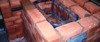
The heat exchanger of such a boiler is installed level on a solid concrete foundation, on which a blower chamber is first laid out of brick (ordinary clay or refractory) to the size of the boiler and a grate is installed above it.
After installing the heat exchanger, the walls of the firebox are laid around it from refractory (best) or high-quality clay bricks - 1/2 brick.
During laying, two doors are installed (pictured below):
- lower - at the level of the grate, for cleaning ash and waste, as well as for igniting fuel from below;
- the top one is for loading firewood or coal and cleaning the top of the firebox.
You can install two different doors to ignite the fuel and clean the blower, as in Fig. 5.
Fuel can be placed in such a boiler both horizontally (short logs) and vertically. Compared to horizontal ones, such a solid fuel boiler allows you to increase the burning time of the fuel and reduce heat loss from the upper surface.
Fig.5 Do-it-yourself vertical solid fuel boiler - appearance: 1 - brickwork; 2 - chimney; 3 - upper combustion door for loading fuel; 4 - lower combustion door - for igniting fuel; 5 — blower door (instead of two doors 4 and 5, you can install one); 6 - outgoing pipe; 7 - return.
Features of chimney construction
The chimney of a solid fuel boiler must have a height of at least 5 m from the level of the grate. The pipe can be constructed or installed directly on the boiler, as a top-mounted pipe, or it can be attached, built on a foundation next to the boiler.
Figure 5 shows a boiler with an upper chimney without a cooking stove. If there is a need to install it, then the foundation is arranged with the calculation of laying the chimney on the side.
The laying of the pipe must be carried out simultaneously with the laying of the walls of the boiler, 1/2 brick thick, or you can install a metal, ceramic or asbestos-cement chimney.
Shaft-type boiler made of bricks
You can also build a so-called shaft-type boiler from brick.
Its design is different in that fuel is loaded through a hatch into a high loading chamber (shaft - hence the name of the boiler). It is ignited from below, through the lower door, and the hot combustion products exit through another chamber in which the heat exchanger is located. Most often, for such boilers, rectangular heat exchangers made of sheet metal are used with 2-3 rows of vertical pipes embedded in them, through which flames and hot flue gases pass, thus heating the coolant (as in the video below). The burning duration of such a boiler can be adjusted by the height of the shaft (loading chamber) and by adjusting the air supply. Rice. 6 Shaft-type boiler made of brick.
Definition with project parameters
There is no exact definition for this concept. The corresponding equipment appeared as a response to consumer demands to increase the level of comfort during operation and increase heat production per unit of energy resources used.
The main disadvantage of classic boilers is the need to regularly add fuel to the firebox. The following factors also create difficulties:
Various designs
To solve the problems noted above, various solutions are used. In order not to frequently add new portions of fuel, the size of the firebox is increased. Placing a pressure device on top and dosed air supply help to make the combustion process uniform.
It will be easier to create drawings of long-burning solid fuel boilers with your own hands after a detailed study of the standard design:
The disadvantage of this design is the impossibility of arbitrarily placing firewood into the firebox. A significant advantage is the increased duration of one working cycle to 24 hours or more.
In the following design, fuel can be added as needed. Pyrolysis technology is used here. It is characterized by a dosed supply of oxygen and low combustion intensity. Smoldering firewood releases flammable gas. It burns in an additional chamber.
This installation makes full use of fuel. Combustion products contain a minimal amount of soot. Optimal adjustment of work processes is difficult.
Gas and diesel units do not have the mentioned disadvantages due to the ease of dosing the corresponding types of fuel. A similar result can be obtained if you use specially compressed granules from wood waste, seed husks, and other combustible raw materials.
In this option, granules (pellets) are poured into a hopper, from where they are fed by a screw mechanism into the firebox. It is clear that this design allows, if necessary, to quickly increase and decrease the fuel supply. Flexible changes in boiler performance are useful for optimizing operation when the external temperature changes or additional consumers are connected. It is not too difficult to work with granules during transportation and storage.
They increase the efficiency of boilers using complex structures of output units. In such structures, the temperature of the coolant increases. The hollow walls of the housing perform similar functions.
Related article:
Long-burning wood-fired boilers for the home. The need to frequently add firewood is very inconvenient. However, there are boilers that require attention once a day. More details in a separate publication.
DIY drawings of long-burning solid fuel boilers
Before looking for the appropriate documentation, it is necessary to more precisely determine the design. The first design of a long-burning solid fuel boiler is preferable; it will be easier to create it yourself.
For heating a relatively small private house with a total area of 150-250 sq. m. The following sizes will be sufficient:
With a height of just over 1.5 meters and a width of about 40 cm, it will not be difficult to find a suitable place for installation. But we must take into account the need to create technological passages for maintenance. You will need free space at the top for mounting the winch and other equipment.
To implement private projects, it is not necessary to comply with GOSTs. But the more detailed the drawing of a long-burning solid fuel boiler with your own hands is, the easier it will be to eliminate errors in the early stages.
Note! Do not forget that the set of drawings with dimensions must be supplemented with a list of products that will need to be purchased separately. Include factory-made components, tools, consumables and materials, construction gloves and other personal protective equipment.
Rotary kilns
Rotary kilns with a length of 30–100 m, a diameter of 2–4 m, an inclination angle of 3–4° and a rotation speed of 0.5–1.2 rpm. Their specific daily productivity reaches 500-700 kg/m3 based on the direct volume of the calcination drum. The productivity of furnaces increases with their length, and at the same time fuel consumption decreases.
There are various ways to reduce fuel consumption for lime burning in rotary kilns. The same measures are suitable for recycling the heat of gases leaving furnaces at a temperature of 750-800 ° C. In particular, heaters are placed behind the furnaces, into which the lump material intended for firing is directed. From here, at a temperature of 500-8000C, it enters the rotating kiln, and from it into the refrigerator. With this method of kiln operation, the heat consumption for firing is reduced to 4600-5030 kJ/kg of lime.
Fuel oil or gas is used as fuel burned directly in the furnace drum with a torch. For burning lime, it is not recommended to use solid pulverized fuel with a high ash content, since the ash settles on the limestone and at high temperatures forms fusible compounds that form deposits that disrupt the normal operation of the kiln.
Limestone, when moving along the drum, passes successively through the zones of drying, heating to a temperature of 1123-1153 K (850-880 ° C), firing and pre-cooling. When firing dense limestones, there is no drying zone in the kiln due to the low moisture content of the material. The heating zone is usually 50-70% of the furnace length, the firing zone is 25-30%. The length can be adjusted by changing the length of the burning fuel torch. Next, from the firing zone, the lime enters the pre-cooling zone, which usually occupies about 5% of the length of the kiln. Final cooling takes place in a special refrigerator. The air, heated in the refrigerator to 573–673 K (300–400 °C) by cooled lime, enters the furnace for fuel combustion as secondary air. Primary air in an amount of 15-20% of the total combustion consumption is supplied through the burner. To speed up heat exchange, chain and metal cell heat exchangers are installed in the heating zone. You can also use baked heat exchangers of the cyclone type and in the form of a conveyor grid.
Heat exchange in rotary kilns occurs by the radiation method, and in shaft kilns - by convection. In rotary kilns, this is due to a larger heat exchange surface and the fact that 3-atomic gases (V2=VCO2+VH2O+VSO2}3-atomic gases) are capable of transmitting heat transfer by radiation quite well.
Our development
The advantages of rotary kilns are as follows: with a length of 30-100 m and a diameter of 1.8-3 m, productivity reaches 400 - 500 tons/day, which is 2-4 times higher than that of shaft kilns. The second most important technological advantage of lime burning in rotary kilns is the short time it takes for the material to pass from the loading point to the exit from the kiln, which ensures efficient process control. In addition, rotary kilns provide a compact technological scheme, allow you to automate the process and reduce capital costs for the construction of workshops. In rotary kilns, high-quality lime can be produced by firing at medium and fairly high temperatures. Due to the short residence time of the material in the oven, the risk of burnout is minimal. At the same time, lime is much more homogeneous in composition and contains fewer impurities.
Advantages of rotary kilns: 1) high quality lime; 2) use of any raw materials; 3) use of any type of fuel; 4) obtaining any type of lime (construction, metallurgical)
Disadvantages: 1) high metal consumption; 2) large capital investments; 3) significant fuel consumption (compared to mine); 4) high energy consumption (compared to mine ones).
Summary. Rotary kilns make it possible to produce high-quality soft-burnt lime from small-piece limestone and from soft carbonate rocks (chalk, tuff, limestone-shell rock), which cannot be fired in shaft kilns due to the tendency of these materials to “hang” in the shaft, leading to a violation of the firing technology .
Lime burning in gas-fired shaft kilns. Requirements for the fractional composition of raw materials. Fuel burners and their location in the stove. The design of furnaces, the advantages and disadvantages of their operation.
Manufacturing a long-burning solid fuel boiler: reviews and algorithm of actions
Before you start, study the opinions and advice of real users. As their reviews indicate, equipment of this type, with the correct implementation of technologies, can be made by yourself.
To create a design without unnecessary difficulties, finished products with the necessary parameters will be useful. A metal pipe with a diameter of 350 mm, a height of 1.5 meters, and a wall thickness of at least 3 mm is suitable. Of course, some other dimensions will have to be adjusted accordingly.
A bottom cut from sheet steel is welded to it. Don't forget the legs. They must withstand the weight of a heavy structure without damage. For some inlet and outlet openings, pipe sections with suitable dimensions are suitable. Strengthening and attachment points for attachments are created from channel sections.
The finished structure is cleaned. To protect against corrosion and have good aesthetic characteristics, it is covered with layers of metal primer and paint. They use types of coatings that are resistant to high temperatures. After installing the winch and other additional devices, check the functionality of all mechanisms and drives. The boiler is connected to the air supply, water supply and heating systems, chimney, 220 V electrical network. Perform a test run and eliminate any identified deficiencies
Note! Do you know how to make a long-burning solid fuel boiler yourself, but doubt the accuracy of individual operations? In this case, the creation of welding seams and other complex actions must be studied in advance. This equipment must be reliable during operation, so it is better to eliminate unnecessary risks.
The process of making a solid fuel boiler from brick with your own hands
What materials and tools are needed for construction?
To build a solid fuel boiler with your own hands, you need to have the slightest knowledge of welding, mason skills and be able to use a gas cutter. It is advisable to understand the marking and cutting of working material, as well as have an understanding of working with power tools. With such a wealth of knowledge, you will be able to quickly build a high-quality solid fuel boiler at a minimal price. To do this you will need the following materials:
- clay, brick;
- grate;
- pipes;
- gravel;
- water;
- sheet metal;
- doors;
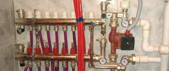
- water pump and water heating device.
It is necessary to prepare the following tools:
- welding machine;
- Bulgarian;
- cutting torch;
- a marker that is clearly visible on metal;
- spatula for putty;
- level;
- pliers;
- roulette;
- electric drill.
To protect yourself, it is important to prepare personal protective equipment (goggles and mask) and only then begin making a brick cauldron.
Stages of work
Vertical solid fuel heating devices are popular, which you can design yourself as follows:
- Prepare the heat exchanger and take dimensions from it for the manufacture of the combustion chamber.
- Build a foundation of brickwork or rubble stone.
- Lay the base of the boiler with a waterproof roofing felt pad.
- Line the bottom of the chamber and the ash pan with the door with stove bricks and separate them from each other with a cast iron grate.
- Install the TO and lay the walls out of brick, leaving a gap of 1.5-2 cm.
- A door is attached in front to cover the stored fuel, and a hole is left for the chimney at the back.
- A cast-iron hob or a thick metal sheet covered with a layer of brick is laid on top of the chamber walls if you do not plan to use the boiler for cooking.
- The smoke exit channel is located on the side or on top of the combustion chamber, made from a metal pipe or building material.
- When the masonry has dried well, the heat exchanger pipes are attached to the pipeline using couplings or welded.
- Finally, a test fire is carried out and the operation of the heating device is checked.
Return to contents
DIY long-burning solid fuel boiler: video instructions and conclusions
To manufacture some complex structures, you will need to first equip your own workshop. You will have to master working with welding equipment and purchase specialized tools and devices. If it is not useful in the future, then the corresponding costs will have to be taken into account when calculating the total cost.
The materials in this article, information from drawings and videos will help you create the right long-burning boiler with your own hands. But for a correct assessment, you need to check how much it will cost to complete the relevant order with the help of professionals.
Source: aquatic-home.ru
Design and operating principle
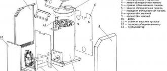
There are two types of long-burning mine boilers:
- Device with conventional fuel combustion.
- Pyrolysis unit.
They consist of two chambers that divide the boiler into two vertical parts. The first burns wood, the second contains a heat exchanger .
The design of a mine boiler with conventional combustion is simpler:
- Firebox. It makes up 50% or more of the volume of the entire device. This part of the long-burning boiler has a large height (almost equal to the height of the unit), small width and depth.
- Loading hatch. Located on the top or side of the firebox .
- Ash chamber. Placed under the firebox .
- Grate. It separates the ash and combustion chambers .
- Ash door. It has dimensions that allow you to gain access not only to the ash pan, but also to the bottom of the firebox. is placed on it to regulate the air supply .
- Heat exchange chamber. Inside it is a water or fire tube heat exchanger . It has a hole through which carbon monoxide generated in the firebox enters.
- Chimney. It has a flap.
Such a mine boiler works as follows:
- Firewood is set on fire in the firebox.
- Hot carbon monoxide exits through the hole into the heat exchange chamber.
- The gas heats the coolant.
- Cooled smoke exits through the chimney, and heated water enters the heating system.
pyrolysis mine boiler has almost the same design , but it is more complicated. The difference lies in the availability:
- Combustion chambers and carbon monoxide afterburning. Placed in the lower part of the heat exchange chamber. Their walls are made of fireclay bricks.
- Secondary air supply pipes. It is located inside the combustion chamber. A special feature of the pipe is the presence of a large number of holes.
- The valves are at the top of the wall that separates the two chambers.
During pyrolysis, firewood decomposes into coke and various flammable gases. The latter enter the combustion chamber, mix with air and burn. The remaining gases burn out in the afterburning chamber. The generated heat heats the coolant.
Construction of a shaft furnace
Most typical mine-type units consist of four main parts, these are:
- Material loading unit;
- Metal unloading unit;
- Smoke removal system (chimney);
- Heat treatment chamber (working space).
Several examples of devices of different types of shaft furnaces:
- In the process of loading charge or metal, conveyor-type mechanisms are used, as well as pulley and skip devices. Their choice is determined by various factors, such as the type of material being charged and the conditions under which the shaft furnace is operated. The most versatile option is a skip-type mechanism, it uses a reversible bucket and a winch.
- The design of the device for unloading finished products consists of several blocks, its main part is an intermediate storage tank, which, dosed, supplies and seals the produced material.
- The exhaust gas removal system consists of several pipes located behind the shaft thermal plant. In modern models, this system is quite complex, equipped with automation and a number of filter elements.
- The main chamber, in which the processes of combustion of raw materials and melting (or heat treatment) of the material take place, has external controls. The operator servicing such a device uses them to set the required temperature conditions, according to the technological maps.
- The inside of a shaft furnace is usually lined, that is, lined with special fire-resistant minerals or blocks of bricks. The best refractory materials for shaft furnaces are fireclay bricks, refractory fiber and corundum.
Many units with operating temperatures up to 1000 degrees are equipped with ventilation devices installed above the hearth or in the area of the furnace lid. They are needed for active mixing of the gas environment inside the thermal chamber, as well as for uniform, rapid heating of processed products or non-ferrous metal mixtures.
Materials
To make a mine-type pyrolysis boiler, you need to stock up on:
- Sheet steel with lining. Thickness 3-5 mm. Other steel should not be used, since pyrolysis is accompanied by high temperatures and a regular alloy quickly burns out.
- Sheet steel with a thickness of 1-2 mm .
- Fireclay bricks.
- Pipes with a diameter of 13, 5 and 2.5 cm .
- Corners with dimensions 4x4 cm. An alternative could be a profile pipe with the same dimensions.
- Double ash door. It is desirable that it have an asbestos gasket. It must have a valve to regulate the air supply.
- Door for cleaning the heat exchange chamber.
- Valves. 3 pcs. One is intended for the chimney, the second will be installed on the partition between the chambers, the third is necessary to regulate the air supply to the combustion chamber.
- Basalt wool.
- Galvanized sheet.
Before buying materials, you need to calculate the minimum power of a long-burning mine boiler and draw up or find in open sources a drawing of the device.
Operating principle of the boiler
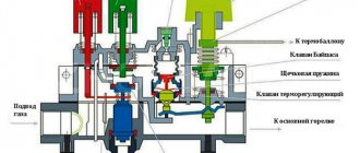
Heat in the Kholmov boiler is obtained through two types of heat generation:
- direct fuel combustion;
- afterburning of solid fuel gases.
The pyrolysis boiler is designed in such a way that the incoming air flow does not provide sufficient air volume for good combustion. Therefore, some amount of fuel simply burns, and some simply smolders. Due to smoldering, a lot of smoke appears with a high content of soot and resin. Smoke gases, when passing through hot coals, are further enriched with substances and create even more active gases.
Kholmov mine type pyrolysis boiler
Such a mine-type wood-fired boiler can operate stably for about 12 hours on a single charge, which is several times longer than standard coal or wood-fired units. It is precisely because of this that the Kholmov boiler is called a long-burning boiler. The firebox of the device is very large and holds much more fuel than the chamber of classic solid fuel boilers.
The unit with a power characteristic of 15 kW has a combustion chamber for 180 liters of fuel. Combustion occurs only in the lower 20 cm of the entire planting. The “reserve” fuel on top waits until the fuel below burns out and gradually takes its place. Smoke gases accumulate at a height of 30 cm above the smoldering coals. A larger volume of incoming air moves under the grates and passes under them into another pyrolysis afterburning furnace. This air attracts smoke gases that are located above the combustion layer. The smoke moves through the coals and becomes enriched, thereby increasing the quality of the pyrogen gases.
The second and first shafts are separated by a vertical partition. Only at the bottom of this wall there is a small gap. Through this hole, with the help of draft, fire is sucked from one chamber to another. Here below there is complete combustion of wood gases, and at the top there is a convection heat exchanger. The highest heating is achieved in the lower part of the second chamber (temperature up to +800 °C). Most of the heat energy in this area passes into the water jacket of the heating unit as radiation. The remaining heat from combustion gases is collected by a convection-type water-tube heat exchanger.
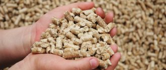
Mine boilers can operate on both wood and coal, pellets, briquettes, wood chips, and sawdust. To increase the efficiency of the heating unit, it is better to minimize the use of coal fuel. The fact is that coal is a product of organic decomposition and when it is burned, almost no pyrogases appear.
You can read more about the Popov gas generator boiler in this article.
Manufacturing of the main part
The main part is a homemade body, which is divided into chambers with various functional devices. The body is made as follows:
- They study the drawing of a homemade unit and determine the dimensions of all metal parts .
- Draw rectangles on sheet steel with lining, which will be the walls and individual metal parts of a homemade shaft-type boiler.
- Sheet steel is cut into pieces. This is best done using autogenous welding.
- Weld the side walls of the body.
- In the sheet, which will be the partition between the combustion and heat exchange chambers, two holes are cut out : one should be at the top, the other should be slightly above the level of the grate. It is desirable that the height of the second hole is 3 cm.
- Place the workpiece inside the body, fix it as indicated in the drawing or watched video, and weld it. A valve is installed in the upper hole and its base is welded. The valve should be on the firebox side. On the other side, weld a neck with a depth of 4 cm.
- A grate is made. To do this, narrow longitudinal holes are cut out in a piece of sheet steel with a lining . The grate can be purchased, but must be made of steel with a lining. A product made of cast iron is not suitable, since after several months of operation of a homemade shaft-type boiler it will warp.
- The grate is welded.
- Holes are cut out in the side walls for the ash door and the combustion chamber cleaning door. Necks need to be welded around the perimeter of the holes. They should protrude outward and inward by 6 and 3 cm, respectively . It is better to weld the neck for the hole in the afterburning chamber after the heat exchanger has been welded.
- Two rows of corners or profile pipes are welded to the inner walls of the thermal chamber . The top row is placed 3-4 cm from the top. The lower one is at the level of the bottom of the afterburning chamber. These corners will become part of the water jacket. You cannot make a water jacket around the pyrolysis chamber, because this will disrupt pyrolysis.
- The heat exchanger is welded to the inside of the water jacket (its manufacture is described below).
- Weld the bottom of the afterburning chamber. It should be at the level of the grate. In this case, one third of it should be horizontal, and the rest should rise upward at an angle. The size of the angle depends on the drawing. The part that is located near the internal partition is made horizontal.
- is cut above the bottom for the air supply pipe .
- A large number of holes are drilled in a pipe with a diameter of 5 cm and welded to the hole in the body. In this case, the pipe is placed so that it protrudes 6 cm from the outside. This part should not have holes. A valve is fixed at the end of the pipe.
- The walls of the combustion chamber are lined with fireclay bricks. To adjust the material to the required dimensions, it is cut. The top of the chamber should be a brick protruding inward. There must be a hole between the bricks for further movement of pyrolysis gas .
- A similar process is done in the afterburning chamber.
Boiler assembly
The unit must be assembled in the following sequence:
- First, the body is made by attaching the side walls and frames of the openings to its bottom with short seams. The bottom frame of the ash pit opening is the bottom of the housing itself.
- From the inside, corners are welded to the body, on which the firebox grate pan (grid) will be placed.
- Now you need to weld the grill itself. The corners of which it consists must be welded with the outer corner down, so that the air coming from below is evenly distributed over the two inclined surfaces of each corner.
- Next, a firebox with a heat exchanger is welded to the corners on which the grate is laid.
- The doors of the firebox and ash pan are cut from steel sheet. From the inside they are framed with a steel strip laid in two rows, between which an asbestos cord must be laid.
Heat exchanger manufacturing
It will be a water jacket with several rows of horizontal pipes . You should not make a heat exchanger with vertical pipes yourself, because the direction of movement of the coolant will coincide with the direction of movement of carbon monoxide. Because of this, efficiency drops significantly. The greatest efficiency is obtained when the directions are opposite.
The heat exchanger is made like this:
- Weld a square or rectangular shell . The width and depth should be 6 cm less than the similar characteristics of the heat exchange chamber.
- Two holes are cut in the shell. One should fit with the hole for the valve in the partition, the other with the hole for cleaning the afterburner chamber.
- At the top of the other two opposite sides of the shell, holes are drilled for tubes with a diameter of 2.5 cm . To do this, fix the metal bit in the drill. Make three rows of holes. The holes should be in a checkerboard pattern. It is important that the holes on one wall are higher than similar holes on the opposite side .
- The pipes are cut into pieces, inserted into the holes and welded.
Final work
- Weld the top of the inside of the water jacket.
- A hole for the chimney is drilled in it and a pipe with a diameter of 130 mm is welded.
- Drill a similar hole in the upper part of the body of a homemade long-burning mine boiler and weld the workpiece.
- Holes are drilled at the top and bottom of the water jacket, and pipes made from a 2.5 cm pipe are welded.
- Check the tightness of the heat exchanger by filling it with water and raising the pressure.
- Weld the bottom to a homemade mine boiler.
- A profile pipe with dimensions of 20x20 mm is welded from all sides around the perimeter.
- A sheet of steel 1-2 mm thick is fixed on top.
- The combustion and loading doors are welded.
- The entire structure is sheathed with basalt wool and galvanized sheets.
Source: poluchi-teplo.ru
Drawing of a simple long-burning boiler
This design of a solid fuel boiler is quite simple. The heat exchanger can be made of sheet steel in the form of a “water jacket”. To maximize heat transfer efficiency and increase the contact area with flame and hot gases, its design includes two reflectors (protrusions inward).
In this design, the heat exchanger is a combination of a “water jacket” around the combustion chamber and an additional slot-like sheet metal register in its upper part.
Diagram of a boiler with a slot-type heat exchanger
1 - chimney; 2 - water jacket; 3 - slot heat exchanger; 4 - loading door; 5 - firewood; 6 — lower door for ignition and cleaning; 7 - grate; 8 - door for regulating air supply and cleaning the ash pan.
In these options, the “water jacket” is supplemented with heat exchange registers made of pipes in the upper part of the combustion chamber. In addition, such units are designed for cooking food on them. Option 4 is more powerful and has a top loading door.
Rice. 3 Designs of solid fuel boilers with additional registers and hob
1 - firebox; 2 - register made of pipes; 5 — return pipe; 6 - supply pipe; 7 - upper loading door; 8 — lower door for ignition and air supply; 9 — loading door; 10 - chimney; 13 — grate; 14,15,16 — reflectors; 17 - damper; 19 — water jacket; 20 - ash pan; 21 - hob.