Purpose and description of the main components of the AOGV - 17.3-3.
The appearance of the heating gas boiler AOGV - 17.3-3 is shown in Fig. 1 , and its main parameters are given in the table.
| Dimensions (H×W×D), mm | 1050×420×480 |
| Weight, kg | 49 |
| Rated thermal power, kW | 17,4 |
| Heated area, m2 (no more) | 140 |
| Type of fuel | natural / liquefied gas |
| Fuel consumption, m3/h, (kg/h) | 1,87 (1,3) |
| Hot water consumption at 35°C | 5,4 |
| Chimney diameter, mm | 135 |
| Nominal gas pressure, Pa | 1274 |
| Minimum gas pressure, Pa | 635 |
| Removal of combustion products | natural craving |
| Burner type | atmospheric |
| Heat exchanger material | steel |
| Type of installation | floor |
| Automation type | electrically independent |
Construction of a gas boiler AOGV - 17.3-3
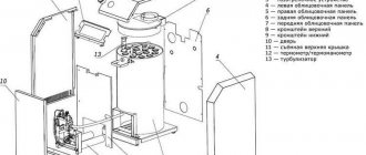
Its main elements are shown in Fig. 2 . The numbers in the figure indicate: 1 - draft breaker; 2 - traction sensor; 3 - draft sensor wire; 4 - start button; 5 - door; 6 - gas magnetic valve; 7 - adjusting nut; 8 - tap; 9 - reservoir; 10 - burner; 11 - thermocouple; 12 - igniter; 13 - thermostat; 14 - base; 15 - water supply pipe; 16 - heat exchanger; 17 - turbulator; 18 - bellows unit; 19 - water drainage pipe; 20 - traction breaker door; 21 - thermometer; 22 - filter; 23 - cap.
The boiler is made in the form of a cylindrical tank. On the front side there are controls that are covered with a protective cover. Gas valve 6 (Fig. 2) consists of an electromagnet and a valve. The valve is used to control the gas supply to the igniter and burner. In the event of an emergency, the valve automatically turns off the gas. Draft interrupter 1 is used to automatically maintain the vacuum value in the boiler furnace when measuring the draft in the chimney. For its normal operation, door 20 must rotate freely on its axis without jamming. Thermostat 13 is designed to maintain a constant temperature of water in the tank.
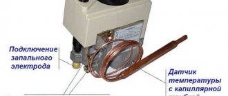
The automation device is shown in Fig. 3 . Let us dwell in more detail on the meaning of its elements. The gas, passing through the cleaning filter 2, 9 (Fig. 3), enters the electromagnetic gas valve 1 . Draft temperature sensors are connected to the valve using union nuts 3, 5 The igniter is ignited when the start button 4 . On the body of the thermostat 6 there is a setting scale 9 . Its divisions are graduated in degrees Celsius.
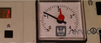
The desired water temperature in the boiler is set by the user using the adjusting nut 10 . Rotation of the nut leads to linear movement of bellows 11 and rod 7 . The thermostat consists of a bellows-thermal bulb assembly installed inside the tank, as well as a system of levers and valves located in the thermostat housing. When the water is heated to the temperature indicated on the dial, the thermostat is activated and the gas supply to the burner is stopped, while the igniter continues to operate. When the water in the boiler cools by 10 ... 15 degrees, the gas supply will resume. The burner lights up from the pilot flame. During operation of the boiler, it is strictly forbidden to regulate (reduce) the temperature using nut 10 - this can lead to breakage of the bellows. The temperature on the dial can be reduced only after the water in the tank has cooled to 30 degrees. It is prohibited to set the temperature on the sensor above 90 degrees - this will result in the automation device triggering and cutting off the gas supply. The appearance of the thermostat is shown in (Fig. 4) .
Malfunctions of the AOGV-23 ZhMZ boiler
___________________________________________________________________________
- Repair and adjustment of AOGV boilers
- AOGV-11.6-3 Economy
- AOGV-17.4 Borinsky
- AOGV-17.4 – Installation and installation
- AOGV-23 — Design and maintenance
- AOGV-23 ZhMZ – Operation
Malfunctions of the Zhukovsky boiler AOGV-23 and their elimination
By pressing the start button it is not possible to ignite the igniter, the flame on the igniter goes out, comes off - The gas valve in front of the device is closed - Open the gas valve. — The hole in the igniter nozzle is clogged — Clean the hole with Ø 0.3 mm wire. — Gas pressure is below 635 Pa (65 mm water column) — Notify the gas department. — The presence of strong drafts in the room, leading to the flame breaking off on the igniter — Eliminate or reduce drafts. There is no spark between the spark plug electrode and the igniter - There is a large gap between the electrode and the igniter - Adjust the gap. — Piezo ignition does not work — Replace piezo ignition. When the start button is released (after holding it for at least a minute with the igniter burning), the igniter flame goes out - Oxidation of the solder on the contacts at the junction of the electromagnet with the contact wire, weak pressing of the pins in the sockets - Unscrew the contact wire fitting from the gas magnetic valve body, clean the contact with a file until shiny (remove oxide film).
Screw the fitting back into the housing. Remove the sockets from the pins and lightly crimp the sockets with pliers. Install the sockets onto the pins.
To avoid breaking the soldering of the electromagnet contacts and the contact wire, do not overtighten the wire fitting when screwing it into the gas magnetic valve body. — The traction sensor microswitch does not work. — Replace the microswitch. — The thermocouple does not produce an EMF, the end of the thermocouple has burned out (the value of the EMF of the thermocouple must be at least 20 mV) — Replace the thermocouple. — The igniter flame does not touch the thermocouple — Install (bend) the thermocouple so that the flame washes the end of the thermocouple (see Fig. 3). — The safety thermostat is faulty — Replace the safety thermostat. The flame of the burner and igniter goes out. Automatic shutdown of the gas supply when the gas boiler AOGV-23 ZhMZ is operating. The draft sensor is triggered - Complete or partial blockage of the chimney - Clean the chimney. — The presence of strong drafts in the room, leading to the flame failure on the igniter — Eliminate or reduce drafts. — The pressure has dropped below 635 Pa (65 mm of water column) — Notify the gas department. — To measure the gas pressure in the network, disconnect the igniter tube from the fitting of the valve body. Connect a measuring device to the fitting.
— Turn the adjustment knob, setting it to 50 - 60 °C. Press the start button all the way, then release it 2 - 3 mm and after 8 - 12 seconds. take readings from the device. The response time of the automatic operation of the gas Zhukovsky boiler AOGV-23 for draft is less than 10 seconds. in the absence of draft in the chimney.
The automatic response time for traction is more than 60 seconds. in the absence of draft in the chimney. — The traction sensor is not adjusted — Adjust the sensor, for this purpose: unlock it, unscrew (or tighten) the adjusting screw by 1-2 mm and lock it again. Check the response time. Repeat the operation if necessary. — The response time depends on the size of the gap between the adjusting screw and the microswitch button. As the gap increases, the response time increases and vice versa. The main burner does not turn off - The "thermal bellows" is depressurized - Replace the "thermal bellows" - The thermostat is out of adjustment - Adjust the thermostat in the response ranges within 50-90 °C. After turning off, the burner does not turn on for a long time. The water in the tank is hot, the radiators are cold - There is no circulation in the heating system - Eliminate reverse slopes in the heating system. Eliminate air pockets in the heating system. Presence of flame at the combustion holes of the main burner when the thermostat is turned off - Leakage of the thermostat valve due to the presence of dirt - Remove the front cover of the thermostat. Clean the valve plug and apply sealing lubricant. The draft breaker door does not rotate or rotates slowly - There is dirt on the door axle - Remove dirt from the door axle and the socket for installing the axle in the draft breaker body.
___________________________________________________________________________
___________________________________________________________________________
- Malfunctions of the AOGV-23 ZhMZ boiler
- Parameters and design of gas boilers AOGV and AKGV
- Boiler automation Baxi Luna-3 Comfort
- Installation and installation of the Baxi Slim boiler
- Adjustments and maintenance of the Beretta Chao boiler
- Determination of error codes and malfunctions of Rinnai boilers
- Errors and malfunctions of the Termet gas boiler
- The meaning of error codes and malfunctions of Vailant boilers
- Determination of malfunctions and errors of Visman boilers
- Questions about servicing Navien boilers
- Questions about malfunctions of Kiturami diesel boilers
- Junkers boilers - Experts answer user questions
- Experts answer questions about Electrolux boilers
- Answers from Nova boiler repair experts
- Questions about Hermann boiler service
- Answers from Daewoo boiler service technicians
- Questions about servicing Ferroli boilers
- Questions from users regarding the repair of electric boilers Evan
- What causes an AKGV gas boiler to light up and immediately go out?
- What is wrong with the Alpha Color boiler if it shows error code E01
- Why does the AOGV boiler light up and go out quickly?
- How to eliminate error E01 on the Baltgaz boiler
- What is the problem if Dani’s boiler lights up but immediately goes out?
- Why does a Danko boiler light up but quickly go out?
- The Demrad boiler has stopped holding pressure, what is the problem?
- Why did the Gaslux boiler start to get hot and make noise?
- What is the reason if the Keber gas boiler lights up but quickly goes out?
- How to eliminate error code 01 on the Kiturami boiler
- What causes a Conord boiler to light up but immediately go out?
- What is the reason if the Lemax boiler lights up and goes out quickly
- Why does a Mimax boiler light up but suddenly go out?
- Why does the Hearth boiler light up but immediately go out?
- Why does a Ross gas boiler light up but go out quickly?
- What is the problem if the Siberia boiler lights up and goes out suddenly?
- Why does the boiler Signal light up and suddenly go out?
- What can cause a Termet boiler to make noise and get hot?
- Why does the Termotechnik gas boiler light up but suddenly go out?
- How can you eliminate error E01 on a Thermon boiler?
- For this reason, the Electrolux double-circuit boiler began to hum and heat up
- For what reasons does a Ferroli gas boiler display an error code A01?
- For what reason does the Immergaz boiler not operate on hot water supply?
- Why does the Navien gas boiler constantly turn off when heating and then turn on immediately?
___________________________________________________________________________
___________________________________________________________________________
___________________________________________________________________________
- Heating boiler piping
- STS boilers
- KVT boilers for solid fuel
- Pellet boiler Peresvet
- Steel floor standing boiler Raton
- Solid fuel boiler Thermology
- Errors and malfunctions of the Termet gas boiler
- Termona boiler repair
- Boiler repair Nova
- Hermann boiler service
- Comparison of gas boilers Lemax Premium-20 and Danko-20s
___________________________________________________________________________
- Daewoo boiler maintenance
- Demrad boiler malfunctions
- Mora boiler malfunctions
- Westen boiler repair
- Malfunctions of Immergaz boilers
- Types of solid fuel boilers
- Models and design of combination boilers
- Liquid fuel and double-circuit boilers
- Cast iron boilers on coal
- Boilers with modeling burners
- Imported boilers for heating systems
How does the AOGV gas boiler turn on?
Actually, the procedure for turning on the device is quite simple, and besides, it is described in the operating instructions. And yet, let’s consider a similar operation with a few comments:
— open the gas supply valve (the valve handle should be directed along the pipe);
- press and hold the start button. In the lower part of the boiler, a hissing of escaping gas will be heard from the pilot nozzle. Then light the igniter and after 40...60 and release the button. A similar time delay is necessary to warm up the thermocouple. If the boiler has not been used for a long time, the pilot light should be lit 20...30 s after pressing the start button. During this time, the igniter will fill with gas, displacing the air.
Possible malfunctions of the AOGV gas boiler
After releasing the start button, the igniter goes out. A similar defect is associated with a malfunction of the boiler automation system. Please note that operating the boiler with the automation switched off (for example, if the start button is forcibly jammed while pressed) is strictly prohibited. This can lead to tragic consequences, since if the gas supply is briefly interrupted or if the flame is extinguished by a strong air flow, gas will begin to flow into the room.
To understand the reasons for the occurrence of such a defect, let’s take a closer look at the operation of the automation system. In Fig. Figure 5 shows a simplified diagram of this system.
The circuit consists of an electromagnet, a valve, a draft sensor and a thermocouple. To turn on the igniter, press the start button. The rod connected to the button presses on the valve membrane, and gas begins to flow to the igniter. After this, the igniter is lit.
The pilot flame touches the body of the temperature sensor (thermocouple). After some time (30...40 s), the thermocouple heats up and an EMF appears at its terminals, which is sufficient to trigger the electromagnet. The latter, in turn, fixes the rod in the lower (as in Fig. 5) position. The start button can now be released.
The traction sensor consists of a bimetallic plate and a contact (Fig. 6). The sensor is located in the upper part of the boiler, near the pipe for exhausting combustion products into the atmosphere. If a pipe is clogged, its temperature rises sharply. The bimetallic plate heats up and breaks the voltage supply circuit to the electromagnet - the rod is no longer held by the electromagnet, the valve closes and the gas supply stops.
The location of the automation device elements is shown in Fig. 7. It shows that the electromagnet is covered with a protective cap. The wires from the sensors are located inside thin-walled tubes. The tubes are attached to the electromagnet using union nuts. The body terminals of the sensors are connected to the electromagnet through the housing of the tubes themselves.
How to clean a gas boiler: some nuances
Before you begin the process of cleaning a gas boiler, you first need to find out what parts will be involved in this. First of all, you will need to clean: the gas filter, the burner with nozzles, the jet, the igniter, the firebox and the chimney. Any of these parts must be cleaned according to your personal specifications.
Scale can accumulate in the passages of the heat exchanger, but soot appears in the chimney and other smoke exhaust channels. It follows from this: in order for the boiler to operate without interruptions, it is necessary to clean not only the main heat exchanger, but also all the inherent smoke channels, the flue, and with it the burner.
When starting to clean a gas boiler, it is important to know and take into account some nuances, without which it will not be possible to achieve particularly high-quality work. It is important to know them in order to do everything according to the rules in the future, without any mistakes.
Small details that are important to know:
- When flushing the boiler, you need to make sure that it is disconnected from gas, water and electricity;
- When dismantling the heat exchanger, it is contraindicated to damage the special sealing parts;
- The heat exchanger must be cleaned very carefully so as not to damage its thin tubes;
- The first thing you need to do is check the tightness of all connections;
- In aggressive solutions, it is primarily necessary to add various stabilizers to protect iron parts.
You can clean the boiler using a special brush.
Before you start cleaning a gas boiler from any company: Baxi, Aton or Vaillant, you must first disassemble the boiler so that you can get to each of the parts, we will need them. Disassembling the boiler is quite easy if you know its structure. You can do this yourself, having first read the instructions with well-deserved attention.
Let's consider the method for finding the above fault.
When repairing a gas boiler, testing begins with the “weakest link” of the automation device - the draft sensor. The sensor is not protected by a casing, so after 6…12 months of operation it becomes “overgrown” with a thick layer of dust. The bimetallic plate (see Fig. 6) quickly oxidizes, which leads to deterioration of contact.
The dust coat is removed with a soft brush. Then the plate is pulled away from the contact and cleaned with fine sandpaper. We should not forget that it is necessary to clean the contact itself. Good results are obtained by cleaning these elements with a special “Contact” spray. It contains substances that actively destroy the oxide film. After cleaning, apply a thin layer of liquid lubricant to the plate and contact.
The next step is to check the serviceability of the thermocouple. It operates in severe thermal conditions, since it is constantly in the flame of the igniter; naturally, its service life is significantly shorter than other elements of the boiler.
The main defect of a thermocouple is burnout (destruction) of its body. In this case, the transition resistance at the welding site (junction) increases sharply. As a result, the current in the Thermocouple - Electromagnet circuit.
The bimetallic plate will be lower than the nominal value, which leads to the fact that the electromagnet will no longer be able to fix the rod (Fig. 5) .
Detailed instructions on how to clean the igniter for a gas boiler
If the igniter flame is cone-shaped and bright blue in color, then we conclude that this is its normal operation. But if the fire has already acquired a yellow or orange tint, then this indicates that the igniter needs to be cleaned. You can clean the igniter yourself, but disassembling the entire boiler is not necessary.
The igniter is considered an automatic device for a gas boiler; it is used to ignite the burner. This part plays a major role in the operation of the entire device. The entire heat exchange process depends on its normal operation.
The igniter, or also called the wick, should ignite very softly, without any pops. If you hear a small pop, like someone shooting, it means that the igniter has broken down or just needs to be cleaned.
Step-by-step cleaning of the igniter:
- We shut off the gas supply;
- We unscrew the igniter itself;
- We clean it thoroughly with a special metal brush;
- Then we blow;
- We install the part in place.
To properly clean the igniter of a gas boiler, you need to watch the Video Training in advance
Before you start cleaning the igniter, you first need to unplug it. By doing regular maintenance of all parts, you will get long and reliable operation of the entire unit and at the same time enjoy the warmth when it’s cool outside.

