In what cases is it necessary to install two boilers?
The decision to install a second boiler most often arises in cases where the base boiler cannot independently carry the entire heat load of the in-house heating system. This scheme will eliminate the problem of power shortages in boiler equipment.
However, there are other reasons for connecting two boilers into one heating system to ensure sanitary temperature in the room:
- Incorrect preliminary calculation of the thermal power of heating installations.
- Increased heated area of the house.
- The need to increase the functionality of the heat supply source, for example, installing a hot water supply system or heating air in heating units.
- Increasing the period of autonomous operation of a heating source when using different types of energy carriers, for example, solid fuel during the day and electricity according to diftariff metering at night.
- The lack of reserves of the main fuel allows the use of two boiler units operating on different types of fuel.
Schemes of heating systems with two or more boilers
By including two or more boilers in a heating scheme, one can pursue the goal of not only increasing heating power, but also reducing energy consumption. As already mentioned, the heating system is initially designed to operate during the coldest five-day period of the year; the rest of the time the boiler works at half capacity. Let's assume that the energy intensity of your heating system is 55 kW and you select a boiler of this power. The entire power of the boiler will be used only a few days a year; the rest of the time, less power is needed for heating. Modern boilers are usually equipped with two-stage forced-air burners, which means that both stages of the burner will work only a few days a year, the rest of the time only one stage will work, but its power may be too much for the off-season. Therefore, instead of one boiler with a power of 55 kW, you can install two boilers, for example, 25 and 30 kW each, or three boilers: two 20 kW each and one 15 kW. Then, on any day of the year, less powerful boilers can operate in the system, and at peak load, all boilers can be turned on. If each of the boilers has a two-stage burner, then setting up the operation of the boilers can be much more flexible: the system can simultaneously operate boilers in different burner operating modes. And this directly affects the efficiency of the system.
In addition, installing several boilers instead of one solves several more problems. Large-capacity boilers are heavy units that must first be brought and brought into the room. Using several small boilers greatly simplifies this task: a small boiler fits easily into doorways and is much lighter than a large one. If suddenly during operation of the system one of the boilers fails (boilers are extremely reliable, but suddenly this happens), then you can turn it off from the system and calmly begin repairs, while the heating system will remain in operating mode. The remaining working boiler may not warm up completely, but it will not allow it to freeze; in any case, there is no need to “drain” the system.
Several boilers can be connected to a heating system using a parallel circuit or a primary-secondary ring circuit.
When working in a parallel circuit (Fig. 63) with the automation of one of the boilers turned off, the return water is driven through the idle boiler, which means it overcomes the hydraulic resistance in the boiler circuit and consumes electricity by the circulation pump. In addition, the return flow (cooled coolant) passing through the idle boiler is mixed with the supply (heated coolant) from the operating boiler. This boiler has to increase water heating in order to compensate for the addition of return water from the idle boiler. To prevent mixing of cold water from an idle boiler with hot water from a working boiler, you need to manually close the pipelines with valves or supply them with automation and servos.
Connecting boilers according to the scheme of primary-secondary rings (Fig. 64) does not provide for such types of automation. When one of the boilers is turned off, the coolant passing through the primary ring simply does not notice the “loss of a fighter.” The hydraulic resistance in the boiler connection section A-B is extremely small, so there is no need for the coolant to flow into the boiler circuit and it calmly follows the primary ring as if valves in a switched-off boiler were closed, which in fact are not there. In general, in this circuit everything happens exactly the same as in the circuit for connecting secondary heating rings, with the only difference being that in this case it is not heat consumers who “sit” on the secondary rings, but generators. Practice shows that including more than four boilers in a heating system is not economically feasible.
Several standard schemes have been developed using HydroLogo hydrocollectors for heating systems with two or more boilers (Fig. 65–67).
Figure 67 shows a universal diagram for any number of boilers (but no more than four) and an almost unlimited number of consumers.
Requirements for a room with two boilers
In the case when the same type of heating sources are selected, the requirements for the furnace are applied to the specific type of fuel used: gas, coal, pallets or electric heating.
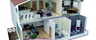
The boiler room in the house needs to be treated with due attention
If units operating on different types of energy carriers are selected, the premises must comply with both, and the larger indicator is selected.
Requirements for units using solid fuel:
- The floor area of the combustion room is selected according to the total thermal power of the devices: up to 32 kW, 7.50 m2 is required, up to 62 kW - 13.50 m2, up to 200 kW - 15.0 m2.
- A unit of more than 30 kW is installed in the center of the combustion chamber to ensure reliable circulation of air masses.
- The surface elements of the combustion chamber: floor, walls, ceiling and partitions are made of fire-resistant building materials, using waterproofing protection.
- The boiler is installed on a reliable foundation made of fire-resistant building materials.
- For units up to 30 kW, the requirements for fire resistance of the floor are lower; it is enough to cover it with a steel sheet.
- The supply of solid fuel is stored in a separate dry room, and the daily supply can be located in the boiler room at a distance of at least 1 m from the boiler.
- The furnace room must have a door and windows installed that can provide reliable air circulation three times based on the existing volume of the room.
Requirements for furnace units with gas-fired boilers:
- Gas boilers with a total power of up to 30 kW can be installed in non-residential premises of a house where there are windows and doors that can provide 3 times air circulation.
- When the power of the gas source is more than 30 kW, a separate furnace room is required with a ceiling height of at least 2.5 m and a total area of more than 7.5 m2.
- If this equipment will be installed in a kitchen in which a gas stove operates, then the room must be at least 15 m2.
Installation Requirements
The installation of a coaxial chimney is not specified separately in the regulatory documents. You must adhere to 2 rules: follow the recommendations of the gas boiler manufacturer and the general requirements for the removal of combustion products from gas-using installations:
- the maximum length of the horizontal pipe section is 3 m;
- the flow area of the chimney must correspond to the dimensions of the outlet pipe of the heat generator;
- if 2 gas water heating devices are installed in the combustion room (for example, a water heater + a boiler), you need to make two separate coaxial pipes; combining them into one is prohibited;
- when crossing walls and ceilings made of non-combustible materials (aerated concrete, brick, reinforced concrete), it is enough to install a metal or asbestos sleeve;
- in a wooden house, you will have to install a fireproof cut in the wall, that is, ensure a minimum distance from the chimney wall to the combustible structure of 380 mm.
Preparation for laying the chimney of a floor-standing boiler through a wooden structure.
A separate nuance is the installation of an umbrella on the head of the flue, which is routed vertically through the roof. The regulations strictly prohibit covering the chimneys of gas heat generators with caps. On the other hand, the unit must be protected from precipitation through the coaxial system.
Advice. Contradictions arising from an imperfect regulatory framework are easily resolved. Contact your local gas utility for specific installation requirements for air/combustion systems. Before installing the boiler, you will still have to obtain permission from them, order a project, and then put the facility into operation.
In the installation instructions, manufacturers of heating units require compliance with the following rules:
- the minimum distance from the ceiling to a horizontally laid chimney is 200 mm;
- the distance from the wall to the end of the pipe is at least 30 cm;
- the height of the head above ground level is at least 2 m, preferably 2.5 m;
Technological indentations that must be observed when installing a chimney - between the chimney outlet and the nearest building or fence there should be a clearance of 600 mm, optimally 1.5 m;
- when choosing the location of the outlet channel, it is important to ensure a distance of 60 cm from the window or inlet opening;
- the slope of the chimney of a turbocharged boiler is made towards the street (value - 10 mm per meter of pipe length);
- condensing units use the energy of water vapor, so the coaxial chimney is installed with a slope towards the heat generator.
On forums, homeowners often ask the question of whether boiler room ventilation is needed with a coaxial chimney. We answer: through the external channel of the system, the fan draws in the amount of air needed for combustion. Ventilation in the furnace room (3-fold air exchange) is still needed; it removes fumes, methane or propane in the event of a leak.
Connection diagrams
Connecting two different types of boilers in one thermal circuit is a very important step. Any even minor mistake, except for the ineffective operation of heating equipment, can create an emergency situation in the house.
The calculation of a two-boiler connection diagram should be entrusted to the design organization so that they can select the most optimal pair of units with parallel or series piping and control options: automatic or manual.
Automatic boilers
From a hydraulic point of view, this scheme does not differ much from the manual control principle, only 2 check valves are installed in it.
This is required in order to eliminate “parasitic” or idle coolant flows through the boiler unit, which is in reserve. This problem is also solved by installing a hydraulic arrow. Check valves are installed on the return line, directed towards each other.
This system will also require a thermostat that turns off the pump for forced circulation. When the coal burns out in the boiler, there will be no point in circulating idle water through the stopped device, thereby creating resistance to the operation of the second device.
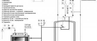
Connection diagram for 2 manually controlled boilers
In this option, to ensure consistency in the operation of the boiler units, only shut-off and control valves are needed. All operational switching between units is performed by the operator’s hands by opening/closing 2 valves on the return coolant line. To completely stop the flow of hot water, you will need to turn off the 4th valves, respectively, in pairs on the supply and return.
In such schemes, I provide expansion tanks to compensate for the thermal expansion of water when heating the boiler from a cold state. In order to save money, it is not recommended to leave one tank, since it may not cope with the load when two boilers are operating.
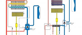
Series and parallel connection
These are two generally accepted schemes for piping two boilers operating in pairs.
Sequential, involves sequential switching on of units without additional lines and nodes. In this case, the first unit in the direction of water movement heats it, and the second unit heats it to the required temperature.
The parallel scheme involves the arrangement of two points of connection of flows on forward and reverse coolants. In this option, the boilers operate independently of each other.
Sequential circuit
The first option is used for small heating sources. In practice, it is quite rare and is considered impractical, since it is impossible to remove one unit for repair operations without affecting the functionality of the other.
Such a scheme will be inoperative if even one unit malfunctions. Today, this scheme has been partially modernized through the installation of bypass lines and additional shut-off and control valves.
Parallel connection of different types of boiler units in a single system is considered advantageous and allows the installation of a hydraulic switch and an automatic control unit.
Parallel connection
Parallel connection of boilers - pros and cons
We reviewed the main boilers above. Now let's look at connecting backup boilers, which should be in the system of any modern home.
If backup boilers are connected in parallel, then this option has its pros and cons.
The advantages of parallel connection of backup boilers are as follows:
- Each boiler can be connected and disconnected from the heating system independently of each other.
- Each heat generator can be replaced with any other equipment. You can experiment with boiler settings.
Disadvantages of parallel connection of backup boilers:
- We will have to work more on boiler piping, more soldering of polypropylene pipes, more welding of steel pipes.
- As a result, more materials, pipes and fittings, and shut-off valves will be wasted.
- The boilers will not be able to work together in a single system, without the use of additional equipment - a hydraulic arrow.
- Even after using the hydraulic arrow, there remains the need for complex setup and coordination of such a boiler system according to the temperature of the water supply to the system, and the supply of return water to the boilers.
The indicated pros and cons of parallel connection can be applied both to the connection of the main and backup heat generators, and to the connection of two or more backup heat generators using any type of fuel.
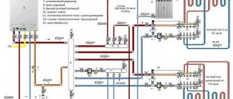
Piping diagrams by type of boiler
It is quite simple to link the operation of two units of the same type, but real operating conditions do not always allow this. More often it is necessary to combine the operation of units not only with different power, but also with different energy carriers.
The most popular pairs of two-boiler schemes:
- gas fuel and electricity;
- gas and solid fuel;
- firewood and electricity;
- propane and electric power;
- heating oil and electricity;
- pellets and electricity.
Connecting a gas and floor-standing solid fuel boiler
This is the most technically complex method of piping two boilers, since it requires the implementation of a smoke ventilation system and compliance with the dimensions of the room for the installation of large fire-hazardous objects.
It is best to entrust the development of the diagram to a design organization, since it must take into account all the rules of safe operation for both gas and solid fuel boilers.
The optimal mode in the heating network is achieved when installing a multi-circuit system; in this case, it is necessary to connect boilers with two independent circuits.
Considering that solid fuel devices are practically impossible to regulate the temperature of the coolant, an open heat supply system with the installation of an expansion tank should be used.
Moreover, a closed heat supply system using gas and solid fuel boilers is unacceptable and is a serious violation of fire safety rules.
Electric and gas
A very effective and easy to manage scheme. By combining gas and electric boilers in one heating system, it is possible to achieve a much greater thermal effect, and with the correct combination of operating modes of the units, the scheme is more economical than traditional gas boilers.
The leading function in this pair is usually performed by a gas boiler unit, which has the lowest cost of thermal energy. The electric boiler is switched on at night using the cheapest tariff for electricity metering.
When choosing the thermal power of equipment, it is necessary to focus on this boiler piping scheme. The gas unit must be more powerful, and the electric boiler must have peak power to operate at night or at peak heat demand. There are no prohibitions on the joint operation of this pair of boilers in regulatory materials. However, their installation will require approval of the boiler house design from both the gas service and energy supervision.
Connecting a solid fuel and electric boiler
Connecting a solid fuel and electric boiler is also an effective implementation of a combined heat supply source. The basic boiler is solid fuel, which is capable of operating at one load for at least 8 hours. It warms up the heat supply facility well.
After the fuel burns out and the coolant cools down to 60 C, the electric boiler is switched on in the mode of maintaining the temperature schedule. For greater energy efficiency, it is advisable to have a hot water storage tank, which is heated by an electric boiler during the night economy mode.
The solid fuel boiler itself is difficult to regulate due to the inertia of the combustion process; it will produce almost nominal performance until the fuel burns out.
In this case, working to heat the primary circuit in the storage tank, adjustment of the heating mode will be carried out in the secondary heating circuit from the storage tank through a three-way valve by mixing cold water from the return coolant with hot water from the supply line.
Is it possible to connect two heating devices to one chimney?
Is it possible to install pipes from two sources at different heights and from different sides in a single-pass ceramic chimney, for example, Tona? For example, from a heating stove and a water heater with the condition that they will not be heated at the same time? Or is a two-pass chimney still needed in this case?
It is possible, but with serious restrictions:
- Gas heat generators must only have separate chimneys. As an exception, during reconstruction it is allowed to connect two gas water heaters to one chimney if there is a cut at least 0.5 m high.
- Stoves, fireplaces, solid fuel boilers in existing buildings (note, in existing buildings and not newly built ones), if it is impossible to organize separate chimneys, can be connected to a common duct, provided that there is a cut at least 1 meter high, if the heat generators are located on the same floor and cuts one floor high, if they are located on different floors. The cross-section of the common channel must correspond to the sum of the cross-sectional areas of the chimneys connected to it.
The cross-section of the combined part of the chimney must be equal to the sum of the cross-sections of the connected channels
Building codes do not provide any concessions in case heating appliances are not used simultaneously. Theoretically, operating heaters, even gas ones, in separate mode is possible, but in practice you will not be able to convince either a gas service representative or an Emergencies Ministry inspector of this. They simply won’t sign your documents or turn on the gas. In addition, the standards were not written simply at the whim of engineers; they establish safe rules for the use of heating equipment.
To summarize: for gas appliances - definitely no, for solid fuel appliances - yes, with the above reservations. The standards must be followed, because the fire inspector is required to check the smoke removal systems in your home. We advise you to find the opportunity to install a separate chimney even if all your heat generators use solid fuel. Still, possible draft problems are not worth the money you can save on a chimney. In addition, if you ever change your equipment to gas, there will be no problems with chimneys.
More detailed information can be found in the following documents:
- For Russia - SP 60.13330.2012 SNiP 41-01-2003 “Heating, ventilation and air conditioning”; “Rules for the production of pipe and furnace works” VDPO, agreed upon by the Main Directorate for the Production of Pipe and Furnace Works of the Ministry of Internal Affairs of the Russian Federation and Gostekhnadzor in 2001.
- For Ukraine - DBN V.2.5-20-2001.
- For Belarus - SNB 4.02.01-03
Multi-fuel boilers instead of two boilers
For small heat supply facilities, it is possible to install boilers whose design allows for the simultaneous combustion of several types of fuel.
The best pairs have proven themselves:
- solid fuel - electricity;
- main gas - liquefied gas;
- main gas - fuel oil;
- liquid fuel - electricity;
- liquefied gas - electricity;
The first pair is the most common and is implemented in many domestic solid fuel boilers, when heating elements with a load of at least 50% of the rated power are installed in the heating circuit.
Thus, having decided to equip a boiler room with two boilers capable of working together, the user definitely wins by receiving a more modern energy-efficient combined heat supply scheme.
With the correct selection of equipment, you can achieve not only the minimum cost of thermal energy, but also increase the level of automation, reliability and safety of the heating source.