Tubular heating elements are the most versatile and suitable industrial heating solution for a wide range of applications. Tubular elements are factory configured in virtually any shape and size. On request, heaters of any bending diameter can be manufactured. Tubular elements are often considered to be the basis of all heating elements. They feature a durable outer shell that helps protect the process heater from physical stress, while high-quality alloys ensure efficient heat transfer from the resistive coil to the coolant.
Depending on the characteristics, shell and shape, electric tube heaters are used in various industrial heating applications (conduction, convection, radiation heating) where high temperatures are required to heat liquids, gases and solids. Even standard factory tube heater models are available in a variety of diameters to adjust watt densities for maximum performance and long life. High quality magnesium oxide is used in the heaters design to efficiently transfer heat from the resistive coil to your heating medium, be it air, liquid or solid. Bend radii are designed with careful expertise to ensure optimal performance while maintaining the “form and function” of your application.
Advantages of tubular heaters and their use:
- Advanced control mechanism
for precise heat transfer and temperature maintenance
- Compact size
, which makes it easy to install, clean, maintain and even replace the heater in case of damage, without taking much time
- Various shapes and sizes available
for each category, specially developed using reliable technology to increase the service life of the product
All electric heaters can be connected to both single-phase and three-phase networks. To connect heating elements to a three-phase network, you can use one of two schemes:
- "Star";
- "Triangle".
For uniform distribution of electrical power and to neutralize the effect of “phase imbalance”, three times the number of heating elements must be connected to each phase
. In this case, the heaters must have a supply voltage of 230 or 380 Volts, corresponding to the phase voltage of the line in accordance with the switching diagram. Thus, heating elements with an operating voltage of 230 Volts are connected in a star configuration, and heaters whose voltage is designed for a load of 380 Volts are connected in a triangle.
Star connections
As an illustrative example, we suggest considering the connection of a star circuit, where three heaters are used. This option is suitable for connecting dry tubular heaters with terminals in the form of 4 bolts and heating element blocks to the network.
This circuit involves connecting every second output of the heater to the corresponding phase. Each first output of the heaters is connected to each other, which contributes to the formation of a common point, which in turn is defined as zero. The connected load is three-wire.
A three-wire connection is used for 380 Volts. Next, we propose to consider connecting the heating element to a three-phase network. Here, turning on and off the voltage is carried out automatically due to the presence of three-pole switches.
The above diagram shows that the contact terminals of the electric heaters, which are located on the right side, are connected to phases A, B, C. The terminals located on the left are connected to a common neutral point. The voltage during operation of the heating elements between the terminals located on the right and the zero point is 230 Volts.
There is also a four-wire star connection method. Electric heaters are connected to a three-phase network with a voltage of 230 Volts. The zero point of the heater leads is connected to the zero point of the power source.
The existing diagram shows that the right terminals of the heating elements are connected to the corresponding phases. The left terminals are closed at a single point, which in turn is connected to the neutral bus of the power source. Between the zero point and the contact terminals, the operating voltage is 230 Volts.
To completely disconnect the load from the electrical network, automatic circuit breakers “3+N” or “3P+N” are used. Such machines allow you to switch power contacts to automatic operating mode. To become more familiar with the “star” circuit in practice, we suggest considering connecting the heating elements of an electric boiler.
Device and connection diagrams of heating elements. Part 2
Hello, dear readers of the site sesaga.ru. We continue to get acquainted with tubular electric heaters ( TEH ). In the first part we looked at the design and inclusion of heaters in a single-phase electrical network, and in this part we will consider the inclusion of heaters in a three-phase network
.
Schemes for connecting heating elements to a three-phase network
For inclusion in a three-phase electrical network, heating elements with an operating voltage of 220 and 380 V are used. Heaters with an operating voltage of 220 V are switched on according to the star
", and heaters with a voltage of 380 V are switched on according to the "
star
" and "
delta
" circuits.
3.1. Star connection diagrams
Consider a star
, composed of three heaters.
to pin 2
of each heater.
Terminals 1
are connected together and form a common point, called
zero
or
neutral
, and this load connection circuit is called
three-wire
.
Three-wire switching on
The circuit is used when heaters or any other load are designed for an operating voltage of 380 V. The figure below shows a wiring diagram for three-wire connection of heaters to a three-phase electrical network, where the supply and shutdown of voltage is carried out by a three-pole circuit breaker.
In this circuit, the corresponding phases A
,
B
and
C
, and the left terminals are connected to
the zero point
. Between the zero point and the right terminals of the heaters, the voltage is 220 V.
In addition to the three-wire circuit, there is a four-wire circuit , which involves connecting a load with an operating voltage of 220 V to a three-phase network. With this connection, the zero point of the load is connected to the zero point of the voltage source.
In this circuit, the corresponding phase is supplied to the right terminals of the heaters, and the left terminals are connected to one point, which is connected to the zero bus
voltage source. Between the zero point and the heater terminals, the voltage is 220 V.
If it is necessary for the load to be completely disconnected from the electrical network, then “ 3+N”
"or "
3P+N
", in which all four power contacts are switched on and off.
3.2. Delta connection diagrams
When connecting in a triangle, the leads of the heaters are connected in series with each other.
Let's consider the circuit for connecting three heaters: output 1
heater
No. 1
is connected to terminal
1
of heater
No. 2
;
pin 2
of heater
No. 2
is connected to pin
2
of heater
No. 3
;
pin 2
of heater
No. 1
is connected to pin
1
of heater
No. 3
.
As a result, we got three shoulders - “ a
”, “
b
”, “
c
”.
Now we apply a phase to each shoulder: to shoulder “ a
"phase
A
, to arm "
b
" phase
B
, and to arm "
c "
phase
C.
3.3. Scheme “heater - thermal relay - contactor”
Let's look at an example of a temperature control circuit. This circuit is made up of a three-pole circuit breaker, a contactor, a thermal relay and three star-connected heaters.
Phases A
,
B
and
C
from the output terminals of the machine are supplied to the input of the power contacts of the contactor and are constantly on duty on them. The left terminals of the heating elements are connected to the output power contacts of the contactor, and the right terminals are connected together and form a zero point connected to the zero bus.
From the output terminal of the machine, phase A
is supplied to the power terminal of thermal relay
A1
and is transferred by a jumper to the left output of contact
K1
and is constantly on duty on it.
The right terminal of contact K1
is connected to terminal
A1
of the contactor coil.
Zero N
from the zero bus is supplied to terminal
A2
of the contactor coil and is transferred by a jumper to the supply terminal
A2
of the thermal relay.
The temperature sensor is connected to terminals T1
and
T2
of the thermal relay.
In the initial state, when the ambient temperature is above the set value, relay contact K1
is open, the contactor is de-energized and its power contacts are open.
When the temperature drops below the set value, a signal comes from the sensor and the relay closes contact K1
.
Through closed contact K1,
phase
A
is supplied to terminal
A1
of the contactor coil, the contactor is activated and its power contacts are closed.
Phases A
,
B
and
C
are sent to the corresponding terminals of the heaters and the heaters begin to heat up.
When the set temperature is reached, a signal comes from the sensor again and the relay gives a command to open contact K1
.
Contact K1
opens and the supply of phase
A
to terminal
A1
of the contactor coil is stopped. The power contacts open and the voltage supply to the heaters is stopped.
The next version of the heater switching circuit differs only in the use of a three-pole circuit breaker with three phase and zero power contacts that can be switched off.
In order not to load the power terminal of the machine, it is necessary to provide a zero bus on which all the zeros will be collected. The busbar is installed next to the circuit elements, and the neutral conductor is pulled from it to the fourth terminal of the circuit breaker.
When connecting heating elements to a three-phase network, in order to distribute the load evenly across phases, it is necessary to take into account the total load power for each phase, which must be the same
.
So we looked at two main connection diagrams for heaters used in a three-phase electrical network.
Now we just have to consider possible malfunctions
and
ways to check the heating element
. Let’s finish here for now.
Good luck!
Source: https://sesaga.ru/ustrojstvo-i-sxemy-podklyucheniya-ten-chast-2.html
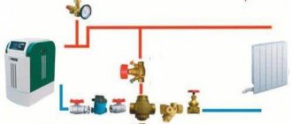
CONNECTING ELECTRIC BOILER TENS
When connecting an electric boiler, different schemes can be used. Based on recent experience, we present to your attention the connection of star-type dry tube heaters with an operating voltage of 230 Volts to a three-phase network. Dry heating elements have high power, so the power wires must be connected to them reliably. Here it is important to follow the diagram for connecting the wires to the contact terminals of the heaters strictly according to the instructions.
When connecting phase wires to the terminals of electric heaters, you should first screw on the M4 nut. After this, you need to apply the washer and put on the tip-ring of the supply wire. Next, the washer is applied again, and a spring washer-grower is placed on top of it. All this is clamped with an M4 nut.
The wire that will be connected to the neutral phase is tightened with an M8 bolt. It will be located in the jumper between the contacts of the heater holes.
After connecting the wires, ground the heater body and the heating element connection wires. Typically, grounding boilers have a bolt on the left side of the electric heater block, to which the grounding conductor should be connected.
As a protective grounding conductor, you can use a separate conductor of the additional potential equalization system or take it from the grounding terminal of the control unit.
After the electric boiler heater has been connected, a protective casing should be installed on the heat exchanger block. To control the temperature of the heated liquid, a temperature sensor should be used. You can also install an air temperature sensor. On the control unit panel for such sensors there are regulators with corresponding markings. Each regulator has a graduation with a temperature code. This way you can easily set the temperature for the coolant. When the coolant temperature reaches the set level, the sensor will give a signal and the heater will automatically turn off. If the temperature level drops below the required values, using the same response principle, the heating device will start working and heating will resume.
Due to the presence of such communications, the operation of the electric boiler is almost completely automated. You will only need to set all the necessary settings modes.
The temperature sensor for water is placed inside the heat exchanger in a specially designated landing area. You can also install it yourself by attaching it to the heating pipe.
The air temperature sensor operates on the same principle. It is simply installed in a room where it measures the overall thermal values of the air.
The electric boiler will heat the coolant until the air in the room reaches the required temperature values.
Different modifications of boilers differ in internal filling, additional functions, level of automation... Only the wiring, cable cross-section, protection and type of network connection do not change.
Schemes for connecting heating elements to a single-phase network.
Tubular electric heaters are designed for a specific power
and
voltage
, therefore, to ensure the nominal operating mode, they are connected to a supply network with the appropriate voltage.
According to GOST 13268-88, heaters are manufactured for rated voltages: 12
,
24
,
36
,
42
,
48
,
60
,
127
,
220
,
380 V
, however, heating elements designed for voltages of 127, 220 and 380 V are most widely used.
Let's consider possible options for including heating elements in a single-phase network.
2.1. Plugging in.
Heating elements with a power of no more than 1 kW (1000 W) can be safely plugged into an outlet through a regular plug, since the majority of electric kettles and boilers that we use to heat water have this power.
in parallel via a regular plug
two heating elements, but both heaters should have a power of no more than 1 kW (1000 W), since when connected in parallel their total power increases to 2 kW (2000 W). Thus, you can turn on several heaters, but their total power should be no more than 2 kW, and to plug into an outlet you must use a more powerful plug.
- How to connect a thermostat to a boiler, including an old one, without terminals...
There may be a situation when you have several heaters lying around at home, designed for an operating voltage of 127 V, you can’t throw them away, and you can’t plug them into the home network. In this case, the heaters are turned on sequentially
, which makes it possible to apply increased voltage to them. When two heaters with a voltage of 127 V are connected in series, their power remains the same, but the total resistance doubles. For example, when two 500 W heaters are turned on, their total power will be 1000 W.
However, this scheme has one drawback: if any of the heating elements fails, then both will not work, since the electrical circuit will break and the power supply will stop.
You must also remember that when two heaters with an operating voltage of 220 V are connected in series, their total power decreases
twice as much, since due to the increase in total resistance, each heater will receive about 110 V instead of the required 220 V.
2.2. Switching on via circuit breaker.
It will be much more convenient if voltage is supplied to the heating elements using a circuit breaker. To do this, it is necessary to provide a machine in the house panel, or install the machine directly next to the heating device. The voltage supply and shutdown will be carried out by turning on/off
circuit breaker.
The next option for turning on the heaters is carried out with a two-pole switch, which is the most preferable, since in this case the phase and zero are broken simultaneously and the heating element is completely disconnected from the general circuit. Voltage is supplied to the upper terminals of the switch, and the heater is connected to the lower terminals.
If an electric heater is used to heat water and the house is grounded
, then to protect against electric shock in the event of a breakdown of the heater insulation, it makes sense
to install an RCD
or a circuit breaker.
- Budget thermostat. Minor modification.
In this case, the grounding conductor
connected to the heating element body or connected to a special screw fixed to the container body. Next to such a screw there is a grounding sign. Let's consider a circuit with a difavtomat:
Protection with a difavtomat works as follows: when the heater insulation breaks down, a phase appears on its body, which, using the least resistance, will “go” along the PE
and will create
a leakage current
.
If this current exceeds the setting, the automatic circuit breaker will operate and turn off the voltage supply. If a short circuit
, then in this case the automatic circuit breaker will operate and de-energize the heating element.
When using an RCD, an additional single-pole circuit breaker must be installed between it and the heater, which, in the event of a short circuit, will cut off the voltage supply to the heater and protect the RCD from short circuit current. In the event of an insulation breakdown, the RCD will cut off the voltage supply.
2.3. Operation of heating elements in temperature control circuits.
In automatic temperature control circuits, the supply voltage to electric heaters is supplied through the contacts of starters, contactors or thermal relays. In total, the connection “ heater - thermal relay”
"or "
heater - thermal relay - contactor
" is the simplest temperature controller that can be used to maintain the temperature in rooms or liquid media. The contactor is used in the circuit for multiplying contacts and for switching powerful loads for which the thermal relay contacts are not designed.
The thermostat can operate in the “ Heating”
" or "
Cooling
", which are selected by a switch located on the face of the relay.
We will consider the operation of the heating element in the “ Heating
” mode, since this is the mode that is used most often.
Let's consider the " heater - thermal relay"
».
The 220 V supply voltage is supplied to the input terminals of the two-pole circuit breaker. From the output of the machine, voltage is supplied to the power terminals of thermal relay A1
and
A2
.
Zero is connected to the thermal relay terminal A2
and the left terminal of the heater.
The phase is connected to the thermal relay terminal A1
and is transferred by a jumper to the left pin of contact
K1
and is constantly present on it.
The right terminal of contact K1
is connected to the right terminal of the heater.
The temperature sensor is connected to terminals T1
and
T2
.
In the initial state, when the ambient temperature is above the set value, relay contact K1
is open and no voltage is supplied to the heating element.
As soon as the temperature drops below the set value, a signal will be received from the sensor and the relay will give a command to close contact K1
.
At this moment, the phase through closed contact K1
will flow to the right output of the heater and the heater will begin to heat up.
When the set temperature is reached, a signal will again come from the sensor and the relay will open contact K1
and de-energize the heater.
Let's consider the circuit “ heater - thermal relay - contactor
».
The 220 V supply voltage is supplied to the input terminals of the two-pole circuit breaker. From the output of the machine, voltage is supplied to the power terminals of thermal relay A1
and
A2
.
Zero is connected to the thermal relay terminal A2
, terminal
A2
of the contactor coil and the lower terminal of the heater.
The phase is supplied to the thermal relay terminal A1
and is transferred by a jumper to the left terminal of contact
K1
, the lower power terminal of the contactor and is constantly present at these terminals.
The right terminal of contact K1
is connected to terminal
A1
of the contactor coil.
The upper power terminal of the contactor is connected to the upper terminal of the heater. The temperature sensor is connected to terminals T1
and
T2
.
In the initial state, when the ambient temperature is above the set value, relay contact K1
is open and no voltage is supplied to the heating element.
When the temperature drops below the set value, a signal comes from the sensor and the relay closes contact K1
, through which the phase is supplied to terminal
A1
of the contactor coil.
When a phase appears at pin A1
coil, the contactor is triggered, its power contacts close and the phase reaches the
upper
terminal of the heater and it begins to heat up.
When the set temperature is reached, a signal will again come from the sensor, the relay will open contact K1
and de-energize the contactor, which in turn will de-energize the heater.
If you have any questions about contactors, you can get acquainted with their structure and operation, and also consider contactor connection diagrams.
You can also watch a video about heaters, which explains and shows the operation of each circuit.
Let's finish here for now, and in the second part we will look at the diagrams for connecting heating elements to a three-phase network. Good luck!
Share with friends:
Another interesting read:
—>
The thermostat (TR), or thermostat, plays an important role in heating equipment. This is a universal device that controls heating systems. Its design can be different, but the function is the same: TR stabilizes the temperature of a given environment for a certain period of time. You need to know how to connect the thermostat so that it correctly fulfills its purpose.
Mechanical thermostat
Connecting the heating element according to the “triangle” scheme
This scheme involves connecting the terminals of the heating element alternately.
A connection diagram of this type means that: pin number 1 of the first heater will be connected to pin number 1 of the second heater; pin No. 2 of the second heating element will be connected to pin No. 2 of the third heater; from the first heater, terminal No. 2 will be connected to terminal No. 1 of the third heating element. If you follow this pattern, you should end up with three arms - “a”, “b”, “c”. Each arm will receive its own phase:
- “a” - A phase;
- “b” - B phase;
- “c” - C phase.
The power of the heaters and their temperature supply depend on the heating element connection diagram
When choosing a heater, the buyer first of all pays attention to its power. Technical practice shows that with a constant connection to a certain network, when transformers are not used, power indicators depend only on the electrical resistance of the resistive element, which is located in the heating device itself. The dependence is defined by the formula:
P=U*I
where P is power,
U is the voltage between the ends of the heating element,
I is the current flowing through the resistive element.
Due to the fact that the current passing through the spiral depends only on the voltage applied to the ends and the intrinsic electrical resistance (R) of a particular section of the spiral, the formula can be simplified:
P=U2/R
From this we can conclude that under constant voltage conditions, power will increase only when the resistance drops.
The electrical resistance of most heating devices directly depends on the temperature supplied by the heaters themselves. But the resistance within a few hundred degrees will be slightly different. It should be understood that with silicon carbide heaters the situation will be completely different. Since they function as a heating element performed by a non-metallic rod, the resistance here will not change linearly. The resistance of such devices can be in the range of 0.5 ... 5 Ohms, which will not allow the heating device to be directly connected to a 220-volt network, much less 380-volt. According to technical standards, silicon carbide heaters can be connected to a standard network, provided that they are assembled in a series circuit. But. It is worth noting that this technique is ineffective if it is necessary to precisely regulate power and regulate a certain oven temperature. The best method is to network electric heaters using laboratory controlled autotransformers or standard statistical electromagnetic devices.
Connecting the heating block according to the star-delta scheme
There are heaters that are manufactured directly for a three-phase network, for example, heating elements or silicon carbide heaters in the shape of the letter W. The method of connecting them depends on the design voltage in a star or delta connection. When connected in a delta connection, this means connecting three heating blocks in which the resistance is equal and each of them is supplied with a voltage of 380 volts. The “star” circuit with a neutral wire is described in detail above and is designed to supply 220 volts to each consumer. The neutral wire is necessary to connect consumers with different electrical resistance.
Connecting a heating element with a thermostat
Let's consider the principle of operation and the connection diagram.
They are used for boilers and heating boilers. We take a universal one for 220V and 2-4.5 kW, a regular one, with a sensitive element in the form of a tube, it is placed inside the heating element, in which there is a special hole.
Here we see 3 pairs of heating elements, six in total, you need to connect as follows: set zero to three and phase to the other 3. We insert our device into the open circuit. It has three contacts, in the photo below you can see one in the center at the top and two at the bottom. The upper one is used to switch to zero, and which of the lower ones to phase should be checked with a tester.
We set the regulator to minimum - we ring the lower left with the upper with the tester - there is a sound signal, but not on the second, now we increase the degree and the tester rings the lower right with zero. This means that the power comes to zero (upper) and goes from it to the heating elements, i.e. are powered up. And the lower left pin can be used for an indicator to indicate when the heating element is turned off.