What is it and why is it needed?
The volume of coolant changes during operation. A change in pressure impairs the performance of the heating main. The pipes heat up unevenly, air accumulates in certain areas, and components become unusable. The pressure balance is maintained manually, but it is better to entrust the change in the amount of fuel to automation, which requires a valve in the system.
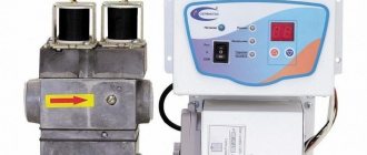
Device specifications:
- DN is the nominal diameter of the connection pipes. The value is used in the case of standardization of standard sizes of collector fittings. Actual DN may vary slightly upward or downward. A similar characteristic was used in the post-Soviet period to indicate the diameter of the nominal bore - Dn.
- PN is the nominal pressure of liquid or gas at a temperature of +20°C. The pressure increase in the system remains within standard limits, ensuring operational safety. The characteristic was used in a similar designation Ru automation in the post-Soviet period.
- Kvs is the coefficient of ability to pass a volume of liquid when the coolant is heated to +20°C. The reduction in pressure in the automation shows 1 bar. The coefficient is used in calculations of hydraulic systems to identify pressure losses.
- Setting range is the difference in pressure change maintained by the automatic device. The indicator depends on the degree of elasticity of the spring.
Bypass valve device
Bypass valve. Schemes and descriptions.
Bypass valve
(overflow valve) is a device designed to maintain the pressure of the medium at the required level by bypassing it through a branch pipeline.
In other words, this is a valve that is installed on an alternative circuit that allows flow through itself in order to prevent an increase in pressure on other circuits.
What is the difference between a bypass valve and a safety valve?
This bypass valve is sometimes also called a safety valve, since its function is somewhat similar to a safety valve. The difference is that a safety valve is needed to protect equipment or a system from destruction by high pressure by removing fluid from the system. A bypass valve is needed in order to begin pumping a medium (liquid or gas) at a certain pressure difference in a closed space in order to relieve the pressure difference in the circuits. The bypass valve maintains system pressure by continuously removing media to stabilize the pressure drop.
What is the difference between a bypass valve and a pressure reducer?
The bypass valve maintains constant pressure at the inlet of the valve (“before itself”), and the pressure reducing valve (Pressure Reducer) maintains constant pressure at the outlet (“after itself”).
Structurally, the bypass and safety valves may not differ from each other. And therefore this device is marked with one technical sign. The only difference is that the safety valve has an outlet channel that leaves the system, while the bypass valve uses an outlet channel to redirect the medium through a closed loop. The bypass valves also have a precise differential pressure regulator, which allows it to be adjusted to the specified required operation in the system.
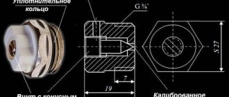
Safety and bypass valve technical symbols:
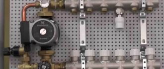
Let's look at the diagram:
A bypass valve is installed in this diagram. Here, the bypass valve serves to firstly prevent the pump from operating under load when the circuits on the manifold are closed. And secondly, if necessary, you can set it to the threshold for stabilizing the pressure drop.
It is necessary to set the bypass valve to the maximum possible pressure, that is, if the pump pressure is 5 meters, then the pressure of the bypass valve should be made a little less, for example, by 4 meters.
What does this give?
When the circuits on the manifold are closed or one or two circuits are working, then a strong pressure drop occurs on individual circuits. Very high pressure on the circuits occurs, which results in higher flow rates on the circuits. This means that the pressure drop on the pressure gauges increases, and the valve begins to let liquid through, eliminating the increase in pressure on the circuits. Thereby stabilizing the pressure on each collector. In general, it’s up to you what pressure you set for the bypass valve.
If the bypass valve is set to 3 meters, this means that the difference on the pressure gauges will not exceed 3 meters. And this means that, regardless of the number of circuits involved, the specified pressure drop on the pressure gauges will be maintained.
Now let's look at the dependency graph:
The stabilization limit begins to arise when the pump flow reaches such large values through the valve that the hydraulic resistance of the valve itself begins to increase, which reduces the flow through the valve.
Let's look at another graph:
The graph shows that in order to stabilize the pressure drop of the circuits, a simple increase or decrease in flow through the valve occurs.
Case from practice:
I came across this phenomenon when the liquid in the pipe begins to make noise. This noise is caused by high pressure on the circuits. This pressure strongly accelerates the liquid through the pipes, which begins to make noise. And this happens because you left the taps on for a small number of circuits. But the pump pumps a lot and if the flow rate is small, then an increased pressure drop occurs. That is, there is an increased speed of water flow in the pipe.
This bypass valve eliminates this cause. It must be installed as shown in the diagram. And if only one circuit is operating, then the bypass valve will begin to allow flow through itself to reduce the pressure created on the circuit.
In general, it is not advisable for the pump to work for one circuit, since the pump is designed for high flow rates! And if you reduce the specified pump flow rate, you may get an undesirable load on the pump. Not only will the pump overheat, but it will also consume more energy.
This bypass valve is suitable for small heating systems, within one or two manifold blocks. But if you want to stabilize the pressure drop without the expense of valve flow, there are automatic balancing valves that can utilize the maximum pump flow. And the bypass valve serves to stabilize the pressure by extinguishing it using the flow method. An automatic balancing valve creates a differential by blocking the passage along the circuit with the valve. That is, it has a valve in series and this valve tightens the passage in order to eliminate flow through the circuit.
You can read about balancing valves here.
For large projects such as heating networks, there are bypass valves with high flow rates, for example:
What is the pressure difference between two points?
Let's consider an example: Let's say we have pressure gauges on the supply and return pipelines, which show the pressure at these points. The difference will be a value that is equal to the difference between the two pressure gauges. That is, if a pressure gauge shows 1.5 Bar, and another shows 1.6 Bar, then the difference is 0.1 Bar.
0.1 Bar = 1 meter of water column.
If you do not understand pressure differences and do not understand what “ pressure”
“Then for you I have a specially developed section on Hydraulics and Heat Engineering, which makes it possible to perform hydraulic and heat engineering calculations.
All about the country house Water supply Training course. Automatic water supply with your own hands. For Dummies. Malfunctions of the well automatic water supply system. Water wells Well repair? Find out if you need it! Where to drill a well - outside or inside? In what cases does cleaning a well make no sense Why pumps get stuck in wells and how to prevent it Laying a pipeline from a well to a house 100% Protecting the pump from dry running Heating Training course. Do-it-yourself water heated floor. For Dummies. Warm water floor under laminate Educational Video course: According to HYDRAULIC AND THERMAL CALCULATIONS Water heating Types of heating Heating systems Heating equipment, heating batteries Heated floor system Personal article on heated floors Operating principle and operating diagram of a heated water floor Design and installation of a heated floor Do-it-yourself water heated floor Basics materials for heated water floors Installation technology of water heated floors System of heated floors Laying step and methods of laying heated floors Types of water heated floors All about coolants Antifreeze or water? Types of coolants (antifreeze for heating) Antifreeze for heating How to properly dilute antifreeze for the heating system? Detection and consequences of coolant leaks How to choose the right heating boiler Heat pump Features of a heat pump Heat pump operating principle About heating radiators Methods of connecting radiators. Properties and parameters. How to calculate the number of radiator sections? Calculation of thermal power and number of radiators Types of radiators and their features Autonomous water supply Scheme of autonomous water supply Construction of a well Cleaning a well with your own hands Experience of a plumber Connecting a washing machine Useful materials Water pressure reducer Hydraulic accumulator. Operating principle, purpose and configuration. Automatic air release valve Balancing valve Bypass valve Three-way valve Three-way valve with ESBE servo drive Thermostat for radiator Manifold servo drive. Selection and connection rules. Types of water filters. How to choose a water filter for water. Reverse osmosis Sludge filter Non-return valve Safety valve Mixing unit. Principle of operation. Purpose and calculations. Calculation of the CombiMix Gidrostrelka mixing unit. Operating principle, purpose and calculations. Indirect heating storage boiler. Principle of operation. Calculation of a plate heat exchanger Recommendations for the selection of PHE when designing heat supply facilities About contamination of heat exchangers Indirect water heating water heater Magnetic filter - protection against scale Infrared heaters Radiators. Properties and types of heating devices. Types of pipes and their properties Indispensable tools for a plumber Interesting stories A scary tale about a black installer Water purification technologies How to choose a filter for water purification Let's think about sewerage Sewage treatment plants in a rural house Tips for a plumber How to evaluate the quality of your heating and plumbing system? Professional recommendations How to choose a pump for a well How to properly equip a well Water supply for the garden How to choose a water heater An example of installing equipment for a well Recommendations for the configuration and installation of submersible pumps What type of water supply accumulator should you choose? Water cycle in an apartment - vent pipe Removing air from a heating system Hydraulics and heating engineering Introduction What is hydraulic calculation? Physical properties of liquids Hydrostatic pressure Let's talk about resistance to the passage of liquid in pipes Modes of liquid movement (laminar and turbulent) Hydraulic calculation of pressure loss or how to calculate pressure loss in a pipe Local hydraulic resistance Professional calculation of pipe diameter using formulas for water supply How to select a pump according to technical parameters Professional calculation of water heating systems. Calculation of heat loss of the water circuit. Hydraulic losses in a corrugated pipe Heat engineering. Author's speech. Introduction Heat transfer processes Thermal conductivity of materials and heat loss through the wall How do we lose heat with ordinary air? Laws of thermal radiation. Radiant warmth. Laws of thermal radiation. Page 2. Heat loss through a window Factors of heat loss at home Start your own business in the field of water supply and heating systems Question on hydraulic calculations Designer of water heating Pipe diameter, flow speed and coolant flow. We calculate the diameter of the heating pipe. Calculation of heat losses through the radiator. Power of the heating radiator. Calculation of the power of radiators. Standards EN 442 and DIN 4704 Calculation of heat loss through building envelopes Find heat loss through the attic and find out the temperature in the attic Selecting a circulation pump for heating Transfer of thermal energy through pipes Calculation of hydraulic resistance in a heating system Distribution of flow and heat through pipes. Absolute schemes. Calculation of a complex associated heating system Heating calculation. Popular myth Calculation of heating of one branch along the length and KMS Calculation of heating. Selection of pump and diameters Heating calculation. Two-pipe dead-end Heating calculation. Single-pipe sequential heating calculation. Two-pipe associated Calculation of natural circulation. Gravity pressure Calculation of water hammer How much heat is generated by pipes? We are assembling a boiler room from A to Z... Heating system calculation Online calculator Calculation program Heat loss of the room Hydraulic calculation of pipelines History and capabilities of the program - introduction How to make a calculation of one branch in the program Calculation of the KMS angle of the outlet Calculation of the KMS of heating and water supply systems Pipeline branching - calculation How to calculate in the program single-pipe heating system How to calculate a two-pipe heating system in a program How to calculate radiator flow in a heating system in a program Recalculation of radiator power How to calculate a two-pipe associated heating system in a program. Tichelman loop Calculation of a hydraulic separator (hydraulic arrow) in the program Calculation of a combined circuit of heating and water supply systems Calculation of heat loss through enclosing structures Hydraulic losses in a corrugated pipe Hydraulic calculation in three-dimensional space Interface and control in the program Three laws/factors for selecting diameters and pumps Calculation of water supply with self-priming pump Calculation of diameters from the central water supply Calculation of water supply for a private house Calculation of a hydraulic arrow and collector Calculation of a hydraulic arrow with many connections Calculation of two boilers in a heating system Calculation of a single-pipe heating system Calculation of a two-pipe heating system Calculation of a Tichelman loop Calculation of a two-pipe radial distribution Calculation of a two-pipe vertical heating system Calculation of a single-pipe vertical heating system Calculation of a warm water floor and mixing units Recirculation of hot water supply Balancing adjustment of radiators Calculation of heating with natural circulation Radial distribution of a heating system Tichelman loop - two-pipe associated Hydraulic calculation of two boilers with a hydraulic arrow Heating system (not Standard) - Another piping scheme Hydraulic calculation of multi-pipe hydraulic arrows Radiator mixed system heating - passing from dead ends Thermoregulation of heating systems Pipeline branching - calculation Hydraulic calculation for pipeline branching Calculation of a pump for water supply Calculation of warm water floor contours Hydraulic calculation of heating. Single-pipe system Hydraulic heating calculation. Two-pipe dead-end Budget option for a single-pipe heating system for a private house Calculation of the throttle washer What is KMS? Calculation of a gravity heating system Designer of technical problems Extension of a pipe Requirements SNiP GOSTs Requirements for a boiler room Question for a plumber Useful links for a plumber - Plumber - ANSWERS!!! Housing and communal problems Installation work: Projects, diagrams, drawings, photos, descriptions. If you're tired of reading, you can watch a useful video collection on water supply and heating systems
Areas of use
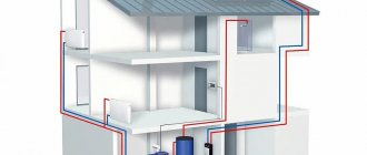
Automation regulates the pressure in the return and supply circuits of the pipeline, intended for closed-type heating lines. Normalization of pressure is carried out when the radiator valves are closed and the thermal load is reduced.
The valve provides operational advantages:
- reduces the load on the operating pump;
- prevents the formation of rust inside the boiler;
- eliminates noise and humming in pipes;
- increases the degree of heating of the energy carrier in the return circuit;
- reduces hydraulic losses.
Bypass valves are used in pipelines of varying complexity. An automatic valve is installed to stabilize the pressure:
- In multi-circuit heat supply systems. Energy consumption decreases when one of the pipeline branches is disconnected, which leads to an increase in pressure power. Maintaining pressure at the required level allows you to avoid collector breakthroughs and overload of the heat generating unit.
- In heating pipelines where temperature regulators are installed, and in hot water lines. The amount of coolant increases or decreases if the fluid temperature is adjusted. It is necessary to restore the pressure balance in the pipeline branch.
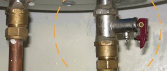
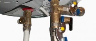
- In water supply lines with installed storage water heaters. Changes in volume due to frequent drawing of hot water lead to imbalance. The bypass device is used to prevent breakdowns and accidents.
Design and principle of operation of any bypass valve
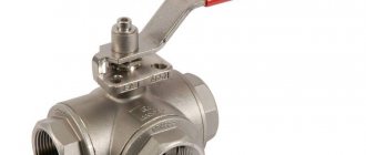
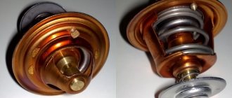
Its body is made of steel or brass. The main element of the internal mechanism is a shutter (flap) that closes the passage opening. The bolt is held closed by a spring. In some models, its role is played by a membrane or diaphragm. The spring force is regulated by an adjustment lever located on the outer surface of the housing.
Valve design diagram
The hydraulics of operation are based on the pressure of the working fluid flow in the pipeline on the valve located inside the housing. As long as the force is less than the lever set by adjustments, the drain hole remains closed. As soon as the pressure becomes greater than the setting pressure, the pressure on the spring leads to its compression. As a result, the drain hole becomes slightly open, and part of the flow is bypassed into the bypass circuit, reducing the pressure in the main hydraulic system.
Then the reverse process occurs - a decrease in pressure leads to the spring expanding and the valve closing, and the valve is again ready for the next reset. Pressure equalization occurs constantly, automatically. When the system operates in the “closed water valve” mode, the bypass channel remains constantly open, ensuring constant recirculation of the media flow through the bypass circuit.
Cross-section of the bypass device
Principle of operation
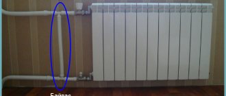
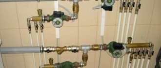
The automatic regulator is installed on an auxiliary line mounted after the pump or acceleration manifold. The bypass connects the leading circuit to the return collector. The liquid bypass is also carried out in the opposite direction if the heating boiler is part of the heating system, which is the principle of operation of the bypass valve. Excess water is discharged to the external environment if the water heater operates in an autonomous line.
Automatic bypass device:
- the damper is located in a metal housing, and a spring is installed there;
- the handle is located on the body and is intended to adjust the permissible pressure;
- Temperature sensors are installed additionally, and a device for replenishing and draining the energy carrier is provided.
The damper puts pressure on the spring, releasing the passage in the housing. The flow is redirected from the supply branch to the outlet circuit. The pressure is leveled out, the indicators are maintained in this state. The spring expands and moves the valve in the opposite direction as the pressure decreases. Liquid does not enter the bypass, and the pressure is equalized under other operating conditions.
A straight-through valve differs from a pressure reducing device and safety automatics. The difference lies in the mechanism for reducing pressure and the frequency of operation.
Difference from other control devices
A bypass valve is often confused with a safety valve and a pressure relief valve. However, despite the general similarity in appearance and functions performed by these devices, there are differences in the mechanism of pressure reduction and the frequency of action.
| Device type | Pressure reduction mechanism | Frequency of action |
| bypass valve | excess working medium is diverted into an additional branch of the pipeline, the pressure of the liquid or gas passing through the main branch is regulated, while the valve is located on the additional | constantly as long as necessary |
| safety valve | excess coolant is released into the external environment or sewerage by opening the valve | occasionally due to pressure changes |
| pressure reducing valve (pressure reducer) | installed on the main branch and regulates the pressure of the working medium by decreasing and increasing its throughput, controls the pressure in the part of the pipeline located after the device | constantly |
We recommend that you read: The use of shut-off valves to shut off the flow in water pipelines
Types and designs
The device is available in the form of indirect and direct action mechanics.
The direct machine has a simple internal design. The damper operates from coolant pressure. The device is used due to its ease of use, insensitivity to contamination and reliability. Automation is characterized by reduced accuracy when setting nominal parameters.
The indirect-acting automation contains a pressure sensor and two valves:
- main, moving from a piston drive;
- pulse, having a small diameter.
When the pressure in the line decreases, the smaller valve puts pressure on the piston, causing the main damper to move. The throughput of the automatic device is regulated by an indirect method. The valves are adjusted more accurately, but are unreliable due to the many operating elements.
The systems use different heating devices. Each type requires a different design of overflow valve:
- A direct valve is installed in electrical systems running on diesel or gas.
- Solid fuel units do not turn off quickly, and smooth adjustment is not possible. Valves are used that respond to changes in the temperature of the energy carrier and an increase in pressure. The automation is connected to the cold pipeline and external sewage system.
- The adjusting handle is used in homes where the owner can independently set the permissible pressure.
- The autovalve is not used in open pipelines. The expansion tank regulates the pressure in the network by compensation.
Differences from other types of safety valves
Other valves installed for the safe operation of pipelines have a similar device and principle of operation. But they differ in purpose and requirements.
| Valve type | Mechanism of action | Principle of operation |
| Bypass | Installed in a bypass circuit and redirects part of the flow into it | Constantly working as needed |
| Safety | Reduces pressure in the system, throwing part of the media out | In case of emergency pressure increase |
| Reducing | By changing its throughput, it regulates the pressure in the part of the main circuit located after its installation site | Full time job |
The bypass valve reduces the load on the system pumps without changing the amount of media in it.
Tips for choosing
Bypass valves correspond to the performance of heat generators, have the appropriate throughput and permissible pressure value. The pipes are connected without fittings; for this purpose, their diameter is selected so as not to increase the vulnerability of the pipeline.
Overflow valves are sometimes sold complete with a water heater or heating unit, or the device is purchased additionally and depends on the type of fuel and technical characteristics. The user’s ability to configure automation and set operating parameters is taken into account. Price plays a role only when choosing a model of devices of the same type with equal parameters, but differing in cost.
Installation
The valve is installed in accordance with the installation instructions. Tips for proper installation of different types of automation:
- a strainer is installed in front of the overflow valve;
- pressure gauges are installed before and after the valve;
- the device is embedded so that its body does not experience mechanical loads of torsion, compression or tension associated with the operation of the connected circuit;
- It is better to select and install automation with the organization of straight sections in front of the valve (5DN) and after it (10DN);
- the overflow device is mounted on pipes located horizontally, inclined or vertical, unless the instructions contain other instructions in this regard.
The automation is configured after water is released into the main during the setup of the entire unit. It is possible to adjust the valve in an empty pipeline if there is an acceptable value.
The autovalve is regulated by creating the required differential at the location of the device; the screw is rotated until the valve opens. The difference is reduced and the moment of closing the damper is monitored, and the device is additionally adjusted. The pressure changes smoothly due to the fact that each revolution of the screw corresponds to a clear range of pressure changes.
Is the oil filter bypass valve as scary as it is made out to be?
From time to time, loud statements are heard in car service circles that modern oil filters do not fulfill their function. And what’s more: “they don’t actually filter anything.” They say that existing filters are only fine filters. And they do not have a coarse filter. And since now the car does not have a coarse filter, which previously was there and worked constantly, the engine is at risk of early critical wear and premature failure.
Of course, modern engines run clean because they are precision manufactured. For this reason, in fact, the word “running in” has disappeared from the vocabulary of most drivers. And it is logical to assume that a fine filter can cope with all the contaminants that arise in a modern engine. However, there are, to put it mildly, enthusiasts who claim that a filter without a coarse filter, which the oil flow cannot bypass in any way, is not a filter at all, but a decoy.
The bypass valve is suspected of sabotage
The root of all troubles seems to be the bypass valve, the purpose of which is obviously to prevent oil starvation of the engine during startup, when frozen oil cannot be pumped through the filter material. And also with a strong increase in oil pressure - for example, when increasing speed during overtaking - so that the flow of oil does not break through or fold the filter curtain.
The fact that, under certain conditions, the bypass valve allows oil to bypass the filter element is interpreted as a factor that critically reduces the life of the engine before overhaul. Let's see if this is true.
Functional purpose of the bypass valve
Indeed, today a car engine, in which the maximum oil pressure can reach 6–10 bar, does not have a coarse filter. For the reason already stated, that no particles should form there that could be captured by such a filter. We are talking about particles larger than 100 microns, that is, 0.1 mm. Agree, this is already quite large garbage, which is simply not supposed to be in a normal engine.
The fine filter bypass valve opens at a pressure of up to 2 bar, depending on the model. When the valve opens, the oil flows back into the engine in transit, that is, it is not filtered. For what periods of time does the bypass valve open, and can opening it cause harm to the engine?
How long is the valve open and what are the dangers?
First of all, the bypass valve must open when the engine starts cold. Until the engine oil warms up to operating temperature, the bypass valve remains open. The time ranges from 5 to 30 minutes maximum, depending on the ambient temperature, oil viscosity and the design of the filter itself - the tighter the bypass valve spring, the faster it will close.
Important Note
Here it is immediately necessary to make a reservation that in the case where the sum of environmental factors, oil properties and filter design actually leads to the bypass valve closing after half an hour - under certain conditions this, as they say, is not very good. Namely, if only short trips are made by car. If during the winter you drive daily only to and from work, and each trip takes less than half an hour, including the time the car warms up, the oil will not be filtered all winter.
However, this operating mode is in any case harmful, both for the engine and for the car’s battery, which will not have time to charge normally. Therefore, experts strongly recommend in any case making a long trip at least once every few days.
The valve also opens briefly during sudden pressure surges in the lubrication system, for example, when overtaking or starting a warm engine. But the total time for such discoveries is short, even if we are talking about cars with a stop-start system. And naturally, it is open most of the time while the engine is running, or even constantly, if the filter curtain is clogged. However, again, on an engine whose condition is within normal limits, this is only possible if there is a radical delay in replacing the filter. Or in the case of some “pathological” chemical reactions in the oil, leading to its concretion (formation of clots and large particles.
So, can we conclude that modern filters do not perform, or do not fully perform their function? And that a system with inconsistent oil filtration significantly brings engine overhaul closer? Of course not! Those who spread such speculation forget (or deliberately pretend to forget) one fact. Namely, that the engine lubrication system is closed. Almost nothing can get into it from the outside. The purpose of the oil filter is to eliminate carbon particles, microscopic metal wear particles, etc.
Wouldn't it be better to play it safe?
Of course, if the air filter breaks and dusty air gets into the engine, and then the contaminants are washed away by the oil from the cylinder walls, it would be better if the oil was cleaned constantly. But if we think like this, then it would be nice if every car was lined with ten-centimeter lead plates and equipped with an autonomous air regeneration system - in case of a nuclear war. It is impossible to design every vehicle system taking into account all the problems resulting from critical non-compliance with maintenance regulations or the purchase of spare parts of questionable quality. Or rather, perhaps, but it will weigh like a tank, cost like an airplane, and travel at the speed of a horse-drawn vehicle. Nobody simply needs such a car.
Outspoken critics of the wastegate say that when it opens, “particles of all sizes enter the engine.” But this is, to put it mildly, distortion. They do not “get into” it, but simply do not leave it for some, relatively short time. And this is definitely better than oil starvation. When the viscosity of the oil decreases upon reaching operating temperature, and the movement is carried out in normal mode, typical for a particular car model, the bypass valve will close and the filter will gradually catch contaminants.