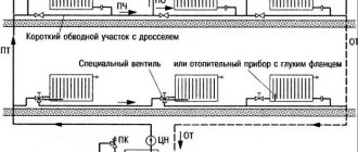
Features of assembling a forced circuit
In order for the forced system to justify itself and function properly, it is necessary to select the right pump and correctly “embed” it into the heat supply main.
Selecting a circulation pump
The main parameters for choosing pumping equipment: device power and pressure. These characteristics are determined based on the area of the heated room.
Indicative indicators:
- for houses of 250 sq.m., a pump with a power of 3.5 cubic meters per hour and a pressure of 0.4 atm is suitable;
- in rooms measuring 250-350 sq.m, install the device at 4.5 cubic meters per hour with a pressure of 0.6 atm;
- if the area of the house is 350-800 sq.m, then it is advisable to purchase a pump with a capacity of 11 cubic meters per hour, the pressure of which is at least 0.8 atm.
In a more scrupulous selection, specialists take into account the length of the heating system, the type and number of radiators, the material of manufacture and the diameter of the pipes, as well as the type of boiler.
Installing the pump in the main
The pump is placed on the return line so that the coolant that is not too hot passes through the device. It is possible to install modern models made of high-temperature resistant materials on the supply line.
When inserting the pump, the water circulation should not be disrupted
It is important that at any point in the pipeline when the pumping unit is operating, the hydrostatic pressure remains excessive
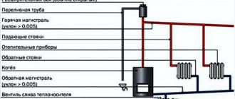
Four acceptable schemes for heating systems with pump circulation and an open expansion tank. Hydrostatic pressure is maintained at the desired level
Option 1. Raising the expansion tank. A simple way to convert a natural circulation system to a forced one. To implement the project you will need a high attic space.
Option 2. Moving the tank to a distant riser. The labor-intensive process of reconstructing the old system and installing a new one is not justified. Simpler and more successful methods are possible.
Option 3. Expansion tank pipe near the pump nozzle. To change the type of circulation, it is necessary to cut off the tank from the supply line, and then connect it to the return line - behind the circulation pump.
Option 4. The pump is included in the supply line. The simplest way to reconstruct the system. The disadvantage of the method is unfavorable operating conditions for the pump. Not every device can withstand high temperatures.
Natural or forced water circulation: which is better for a high-rise building
Systems in which the coolant circulates according to the laws of gravity are for the most part limited to private houses (the heating scheme of a private house with natural circulation is described in the article), individual low-rise buildings located outside the city - or they are designed where there is no constant supply of electricity.
In such buildings, systems with natural circulation are often provided
The main advantage of such a system is that, provided there is a centralized water supply, it does not depend on electricity (read the article about the power supply of multi-apartment residential buildings).
There are other advantages, but there are also disadvantages:
| Advantages | Flaws |
|
|
Considering that in a one-pipe system there is an intense weakening of pressure, and the movement of the coolant slows down, without warming up the premises of a low building to the required temperature, providing for natural circulation, it is better to design a two-pipe system.
Please note: for high-rise buildings with gravitational heat circulation, a single-pipe system is more suitable.
The option with supply and return (two-pipe) is used only when forced movement of the coolant provided by the pump is provided.
Individual heat distribution unit in a multi-storey building with forced circulation
Note: in order to create normal pressure in a two-pipe system with gravitational movement of the coolant, it is necessary to increase the distance from the heat exchanger to the lower heating devices. At a minimum it should be 3 m.
We recommend reading: autonomous heating of apartment buildings.
Features of heating high-rise buildings
High-rise buildings are those with more than 25 floors. This number of floors causes certain difficulties both in supplying water upstairs and in arranging a heating system.
To make this even possible, such buildings are zoned into sections of a certain height, between which there are technical floors, as shown in the photo.
Arrows show the locations of technical floors
This number of technical floors is required in order to accommodate the equipment that ensures the operation of utilities - including heating.
In high-rise buildings, the service area cannot exceed a certain height.
The parameters of technical floors are determined based on the value of the hydrostatic pressure of the coolant in the heating devices of the lower level. Their height must correspond to the dimensions of the equipment placed in them: air ducts, boilers, pumps, heat exchangers.
If the hydrostatic pressure in heating devices varies between 0.6-1.0 MPa, the height of service areas usually does not exceed 55 meters (17-18 floors).
Each of them has its own heating system, connected to an external heat pipeline, but isolated from other systems, has its own heat exchanger, expansion tank, make-up and circulation pump.
In high-rise buildings, individual heating units (IHP) are usually equipped, which are located in the basement floors, where the main pumping equipment and heat exchangers are located. They are almost always rated for a maximum pressure of 1.6 MPa, at which a hydraulically isolated system has a limit of 160 meters.
Technical floor equipment
In a building with such a height, either two zones of 80 m each, or three of 55-50 m each, each with its own contour, are arranged. Moreover, water-water heating can only be in the first two zones - in the third and higher (if there are more floors) steam-water or combined heating is designed.
Note: steam is used instead of water because it does not produce high hydrostatic pressure.
It is supplied to the technical floor preceding the upper zone, which is equipped with its own ITP with a full set of equipment, including control equipment. In buildings whose height exceeds 250 m, electric-water heating can be used.
Heating systems of high-rise buildings are often divided by facades (horizon sides), and each department has its own automated system that regulates the temperature of the coolant.
Coolant supply wiring options
Systems, depending on the organization of supply of heat carriers, come with top or bottom wiring. When a two-pipe heating system with top wiring is used, then the pipeline is laid under the ceiling, and the supply pipes from it are lowered down to the radiators. The return line is installed along the floor covering.
The advantage of this option is that you can easily create a system in which the coolant moves due to natural circulation. The fact is that due to the difference in heights, a flow arises that can provide the required speed of movement, for which it is necessary to ensure a sufficient slope angle.
But the heating system design with overhead wiring has become less popular due to its unaesthetic appearance. True, it can be hidden from above under a suspended or suspended ceiling and then only the pipes leading to the batteries, which can be hidden in the walls, will be visible.
Both the lower and upper wiring options are used in vertical two-pipe structures. In the case of bottom wiring, the supply pipeline is laid below, but higher than the return pipe.
You can also locate the supply line in a basement or crawl space, between the finished floor and its sub-base. In this case, the return line is laid lower. The coolant is supplied or drained to the batteries through holes made in the floor.
When pipes are arranged in this way, the connection will be hidden and at the same time aesthetically pleasing. But in this case, you should select the location of the boiler. If the system operates with forced circulation, the location of the heating unit relative to the radiators does not matter, since the flow will push through the pump. As for structures with natural movement of coolant, the batteries must be located above the level of the boiler, for which it must be buried.
Classification of two-pipe systems
Two-pipe systems have various installation options and can differ in the type of expansion tank (open and closed wiring), mounting method (upper and lower), layout options (vertical and horizontal system) and method of coolant supply (dead-end and sequential wiring).
Open and closed wiring
Any heating system is a closed circuit, in which there is an expansion tank. It is necessary because the coolant expands when heated, which leads to an increase in pressure in the pipes.
When using open wiring, a tank is installed in the circuit, which has contact with the atmosphere, due to which the pressure in the system is stabilized, but part of the liquid evaporates, and therefore it is so important to regularly monitor the volume of water, which creates additional problems when servicing the system. Another disadvantage of open wiring is the ability to use only water to heat the batteries.
Glycols and antifreeze cannot be used in such a wiring; when they evaporate, toxic vapors are formed, which is unacceptable for an open expansion tank
Another disadvantage of open wiring is the ability to use only water to heat the batteries. Glycols and antifreeze cannot be used in such a wiring; when they evaporate, toxic vapors are formed, which is unacceptable for an open expansion tank.
The main difference between closed wiring is the presence of an expansion tank in the heating circuit, which has no contact with the atmosphere. A membrane-type tank effectively compensates for high and low pressure in the system, and also allows the use of antifreeze and glycols for heating.
In a closed wiring there is always a stable pressure, which eliminates the failure of the pump and boiler, and extends the life of the heating equipment.
The ability to use antifreeze prevents the coolant from freezing in winter - this is another bonus from using closed wiring.
Vertical and horizontal system
A two-pipe heating system can be horizontal or vertical. The horizontal organization is used in one- or two-story buildings, and Mayevsky taps are used to bleed air from the circuit on the radiators.
The advantage of the horizontal layout is ease of installation and minimal costs for components. There is only one drawback - the high probability of airing the system.
Vertical layout is more often used in multi-story buildings. Its main advantage is the removal of air from the heating circuit automatically.
Air pockets go up the pipes, where they are released through a release valve or expansion tank. Connection to the riser is carried out on each floor separately, which increases the reliability and efficiency of heating.
Upper and lower wiring
A two-pipe heating system uses upper and lower wiring. In the first case, the heating system is mounted under the ceiling, and branches from the main circuit go to the radiators fixed near the windows and doors of the balcony (areas where cold air accumulates). The lower, outlet heating circuit receives water that cools during circulation.
Top wiring is recommended for large rooms where the quality of heating dominates the interior. In residential buildings, this type of wiring is practically not used.
With bottom wiring, the supply and discharge channels are located near the floor, which makes the pipes invisible. Let us highlight the following advantages of such an organization:
- Easy installation,
- Battery connections and wiring points are on the same level,
- Installation is on the same level and requires minimal pipe consumption.
Passing and dead-end systems
In two-pipe heating systems, a passing and dead-end supply of coolant is used. Multidirectional supply of hot water and return water is used with a dead-end heating method. With this circuit design, bypasses are installed, and the batteries are fixed in closed areas, which allows you to turn off each of the radiators without disrupting the heating operation.
The associated system is called the Tichelman loop
In this case, balancing and adjustment are easier, which is especially important when the heating circuit is long. The coolant moves in the same direction, which increases the efficiency of the heating circuit
Risers
The distribution of coolant through heating devices in a private house is possible horizontally and vertically (stand-up). In multi-apartment buildings in different areas, these schemes are side by side: if the bottling is always a horizontal layout, then the riser is a vertical layout.
What is useful to know about risers in an apartment building?
- On no floor, except for the top floor in a house with bottom filling, should radiator inserts interconnect paired risers. If you insert a heating device between the supply and return risers on the fifth floor of a ten-story building, the inhabitants of the upper floors will freeze: the circulation above the insertion will actually stop.
- In buildings of new projects, one of the paired risers is often made idle (in other words, it is not connected to the batteries). The heating wiring diagram with single risers allows the transfer of paired risers from the basement, without the participation of residents. It is enough just to install a relief valve on the idle thread instead of a plug and move it to the discharge: the air plug will completely fly out at the water front.
- In stalinkas, two radiators are often connected to one riser in parallel, without changing the diameter. Along with this, the riser itself is a jumper between their connections. Such
The heating system wiring is fully operational, but only with a huge (DN25) diameter of the connections.
Practical consequence: if you want to replace the interior wiring yourself, either use heating pipes of the same diameter, or throttle the jumper. The instructions are due to the fact that with a jumper diameter of 25 mm and connections with a nominal diameter of 15-20, the batteries will simply be cold.
What is meant by a closed system in low-rise private houses
The main feature of classifying the heating system of private houses as closed/open types is the design of the expansion tank. An open tank connected directly to the atmosphere is an open system. A hermetically sealed membrane tank is a closed system. This classification has developed in the Russian-language segment of the Internet in fact.
The purpose of the expansion tank is intuitively clear - to compensate for changes in the volume of coolant liquid in the heating system when its temperature fluctuates. Heating the coolant (water, antifreeze) causes an increase in its volume (water heated from 0 ° C to 100 ° C increases in volume by 4.33%), the pressure in the pipes increases (on average by 1.2 - 2.2 bar/ °C) and radiators, increasing the likelihood of emergency situations. The expansion tank installed in the system is capable of temporarily absorbing excess heated coolant. The cooled liquid contracts and leaves the internal volume of the tank.
An open expansion tank is an unsealed container with a removable (lifting) lid and a drain pipe, installed at the top point of the system, where, under the influence of the Archimedean force, bubbles of air dissolved in water move through the risers, escaping into the atmosphere. The reverse movement also takes place - atmospheric air saturates the volume of heated liquid in the tank, entering the system when the coolant is compressed after cooling.
Modern membrane expansion tanks, the design of which is shown in the figure below, prevent the entry of atmospheric air into heating systems.
5. Design of a membrane expansion tank.
Inside it there is an elastic membrane (diaphragm), dividing the internal sealed cavity of the tank into air and water chambers. Advanced models contain nitrogen instead of air. Gas is pumped into the tank under excess pressure, which bends the membrane towards the inlet water pipe. The growing pressure of the heated coolant causes the membrane to compress the gas. The process continues until both pressures (liquid and gas) are balanced.
The membrane tank can be installed anywhere in the system. The best place is considered to be a point on the return pipeline in front of the circulation pump. The liquid reserve inside the tank prevents the occurrence of cavitation in the pump inlet pipe.
In an effort to prevent the water chamber of the expansion tank from being “aired” by air dissolved in the coolant, the inlet pipe is turned upward, as shown in the figure below.
6. Methods for installing an expansion membrane tank.
Additionally, this installation method reduces the temperature of the coolant in the tank, protecting the membrane from thermal loads. High-quality membranes are able to withstand any coolant temperature for a long time, which allows us to recommend both methods of installing expansion tanks.
Forced circulation
Neutralization of almost all of the listed disadvantages is achieved by introducing a circulation pump into the system. As a result, the coolant receives an additional impulse, thanks to which it effectively overcomes the hydraulic resistance of the pipeline. Single-pipe heating system wiring is currently the most popular solution in private homes.
The installation location for the pump can be any section of the highway. However, it should be borne in mind that when rubber elements (gaskets) are exposed to hot water, the service life of the pump is noticeably reduced. Therefore, they try to install the device on the return pipe, because The coolant there is not so hot. A coarse filter must be installed in front of the pump to prevent various contaminants from entering the mechanism. When connecting all instruments and devices, it is recommended to use shut-off valves and bypasses. This will significantly simplify repair and maintenance activities at individual units: in this case, there is no need to stop the entire system and completely drain the coolant.
Strengths of forced circulation heating circuits:
- Possibility of using more complex branched circuits, leading to an increase in the total length of the circuits.
- There is no need to increase the diameter of the pipes. Thanks to the pump, sufficient pressure is created inside the system for movement and uniform distribution of liquid.
- The circulation has a stable speed. This indicator is not affected by the level of heating of the coolant and the installation of the accelerating manifold.
- There is no need to organize inclination angles on horizontal sections of the pipeline, because A pump is used to stimulate the movement of the coolant.
- It becomes possible to insert control devices on all batteries, which ensures the maintenance of an optimal heating level, reducing energy consumption and heating costs.
There are also disadvantages:
- The need for electrical power.
- Noise from a running pump.
- The need for additional capital investments (when compared with the gravity scheme).
Neutralizing them usually does not cause difficulties. To maintain a stable energy supply, an autonomous electric generator is being installed. Systems that provide the possibility of switching to a natural circulation mode have proven themselves very well. To reduce the noise from a running pump, it is usually installed in a non-residential area.
Forced circulation circuit
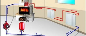
It is the simplest system, because the circuit contains a minimum number of elements.
Equipment composition in a forced scheme:
- Boiler.
- Measuring instruments.
- Radiators.
- Pipeline.
- Safety valve.
- Circulation pump.
- Expansion tank.
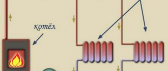
Forced circulation circuit
. System operating principle:
- The prepared coolant with operating parameters is supplied by a pump to the top point of the system.
- Due to gravity, the liquid moves through the pipelines and fills the radiators sequentially (as in the developed diagram).
- Through the return circuit, the water is returned to the boiler by a circulation pump for further cycles.
- The minimum number of nodes in the circuit.
- Relatively high efficiency factor.
- Uniform heating of radiators.
- Low cost of construction and installation work and equipment.
- Possibility of operation in natural circulation mode - when the pump is disconnected from the power supply, the water in the system circulates by gravity.
- Low efficiency of the system in houses with a large area.
Operation of a closed heating system
The closed structure does not have direct access to open air during operation.
The role of the expansion tank is played by the membrane tank. Excess hot water enters it, pushing through the rubber membrane. At the same time, the nitrogen in the air chamber is compressed. The coolant is removed from the tank using a special pump. The absence of oxygen contact with circuit elements extends their service life. The coolant does not evaporate and does not require frequent replenishment. The closed circuit allows the connection of additional heat supply sources with their integration into the overall system. The temperature is regulated by reducing or adding coolant.
A closed system requires constant access to electricity to keep the pumps running smoothly. Despite this difference, it works more effectively in small homes. Multi-storey buildings require a large number of membrane tanks and complex calculations.
System pressure testing
It is impossible to put the heating system into operation without performing a pressure test - testing the strength of pipelines and their connections to the equipment, carried out hydraulically or pneumatically.
Preparing the system for pressure testing
In addition to the tests that are carried out before putting the building into operation, pressure testing is carried out:
- Before the onset of each heating season. The goal is to identify weakened or depressurized areas and push through the pipes in order to free them from sludge that reduces permeability.
- After repairs, during which sections of the pipeline, fittings, and gaskets were changed.
- Post-installation pressure testing is carried out twice: first to identify the presence of leaky connections, and a second time to ensure the operability of the system.
This maintenance helps keep the circuit in working order at all times, which keeps the building warm in the winter.
Subsequence
Actions to test heating pipelines are carried out only outside the heating season, when the coolant is completely removed from the system. Since pressure testing involves increased loads, you have to monitor the pressure using instruments.
The procedure may vary depending on the condition of the heating circuits.
Equipment for crimping
Taken into account:
- pipe material and wall thickness;
- characteristics of fittings;
- number of floors served by the system;
- supply pipeline layout option.
The process consists of several stages:
- Preparations.
- Exposure of the circuit to water or compressed air under pressure half the WP (working pressure).
- Entering data into the accounting journal and drawing up a report.
- Pre-start flushing.
If problems are identified, repair work is carried out, after which the circuit must be tested again.
After the test is completed, the pressure is not reduced for another 30 minutes, during which it becomes clear whether there are leaks.
Features of installation of a one-pipe system
When installing a single-pipe heating system, it is important to consider the following points:
- Use of pipe products of a certain diameter.
- Maintaining the slope of the heating pipe with natural circulation around the entire perimeter of the system.
- Inserting radiators parallel to the main pipeline without breaking it. In this case, you do not need to worry about the lack of circulation in the heating devices; many years of research have proven the effectiveness of the system assembled using a single-pipe design.
- The expansion tank and each heating device must be equipped with an air bleed device. This is especially true for closed-type systems that are isolated from atmospheric air. However, there is one more feature of such systems: if air is not completely bled from one of the radiators, the expansion tank can be excluded from the system.
- Installing chokes and thermostats on heating devices helps to evenly distribute heat between radiators located in close proximity to the boiler and the furthest heating devices.
Single pipe system
In single-pipe systems with top distribution, the coolant is supplied to the highest point and then distributed among the radiators.
They are characterized by serial connection of batteries, which leads to a dependence of the degree of heating on the length of communications and the inability to regulate the temperature of each heating device. When installing single-pipe networks, it is necessary to observe the slope of the supply pipeline, which is 5-7 mm per 1 m.p. towards the movement of the working environment. It improves coolant circulation and provides more uniform heating of rooms. According to the arrangement of pipes connecting heating devices, single-pipe systems can be horizontal or vertical.
The vertical scheme with overhead wiring became widespread during the construction of multi-storey residential buildings in the early 50s of the last century. Today it is in demand both in houses with a height of 4-9 floors or more, and in one-story cottages with an area of up to 100 m2. To eliminate the shortcomings of the system and ensure efficient consumption of thermal energy, single-pipe system radiators are equipped with the following pipeline fittings:
- air ducts. Their functions are performed by Mayevsky taps with a cap or a screwdriver, which serve to remove air accumulation;
- thermostats and thermostatic elements. They allow you to control the heating temperature of each radiator;
- shut-off valves. Installing shut-off valves makes it possible to carry out preventive and repair work without draining the coolant in the system.
Batteries for a single-pipe network with overhead wiring are selected taking into account the operating conditions and the pressure in the pipeline. For apartment buildings with central heating, bimetallic and cast iron models that can withstand significant hydraulic shocks are suitable. In one-story buildings, cast iron batteries are installed. Aluminum heating devices can be used if the composition and acidity level of the coolant is controlled.
Advantages and disadvantages
The demand for a dual-circuit heating system is explained by the presence of a number of significant advantages. First of all, it is preferable to a single-circuit one, since in the latter the coolant loses a noticeable part of the heat even before it enters the radiators. In addition, the double-circuit design is more versatile and suitable for houses of different floors.
The disadvantage of a two-pipe system is its high price. However, many people mistakenly believe that the presence of 2 circuits requires the use of twice the number of pipes, and the cost of such a system is twice as much as a single-pipe system. The fact is that for a single-pipe design it is necessary to take pipes of large diameter. This ensures normal coolant circulation in the pipeline, and therefore the efficient operation of such a design. The advantage of a two-pipe system is that for its installation, pipes of smaller diameter are used, which are significantly cheaper. Accordingly, additional elements (pipes, valves, etc.) are also used with a smaller diameter, which also somewhat reduces the cost of the design.
The installation budget for a two-pipe system will not be much larger than for a single-pipe system. On the other hand, the efficiency of the first will be noticeably higher, which will be a good compensation.
Accurate calculation of a two-pipe heating system
Before starting work, it is necessary to draw up a heating scheme, decide on the material, and make a hydraulic calculation. It is necessary to calculate the pressure drop in the rear section or to calculate the diameter of the pipe.
The calculation is carried out taking into account the following factors:
- Inner surface of pipes and its roughness;
- Section diameter;
- Number of pipe bends;
- Pressure difference between supply and return;
- Number of radiators and their cross-section;
- Locking elements.
When making calculations, use formulas and an axonometric table. You can use a special software program. The most loaded ring or contour is taken as the main object. As a result of calculations, the optimal speed of movement should be from 0.3 to 0.7 m/s.
After the calculations have been made, pipes of effective diameter, the required number of radiators, a boiler, fittings, pipes, an expansion tank, and a circulation pump, if necessary, are purchased.
Two-pipe heating network
A two-pipe heating system with top wiring is characterized by a parallel connection of radiators and provides for the presence of two lines for transporting coolant - supply and return. The first circulates the heated working medium, and the second serves to drain cooled water.
To install a two-pipe circuit, more materials and components will be required. However, the costs and complexity of the work are offset by the following advantages:
- possibility of connecting a “warm floor” system;
- uniform distribution of heated coolant over all heating devices;
- installation of control valves, both on radiator piping and on individual circuits.
Depending on the method of moving the working medium, two-pipe systems are divided into communications with natural and forced circulation. Networks of the first type are used to organize space heating in private houses, the total area of which is up to 400 m2. The diameter of the pipes must ensure transportation of the coolant at a certain speed. To select the correct pipeline cross-section, the heating system is calculated. Networks with overhead wiring and natural circulation must be equipped with an expansion tank, which is placed at the highest point. It is usually located in the attic, so the tank body should be insulated.
Forced circulation in a heating network with overhead wiring is achieved in two ways. In the first case, the pipeline is equipped with a circulation pump and a membrane tank, which is installed on the direct section of the return line. Heating networks of this type are used to heat private houses, so cast iron or aluminum radiators can be used for their installation. When installing aluminum models, the composition of the coolant should be monitored. In multi-storey buildings with central heating, circulation is ensured by high pressure in the network. For long-term and uninterrupted operation of communications, batteries are selected that are resistant to water hammer.
The list of TM Ogint products includes a large selection of radiators suitable for installing systems with various types of overhead wiring. Equipping pipelines with shut-off and control valves will allow you to effectively use thermal energy and control its consumption.
Pressure testing of the heating system
If you want your heating system to work smoothly and without any problems, it needs to be well designed and installed. But as it turns out, this is not enough. The equipment must be put into operation.
And for this, nothing more than pressure testing is done - hydraulic tests, pressure testing of the OKPD heating system - a necessary test that must be carried out not only when installing the system, but also when replacing or repairing a heating device and in preparation for the next heating season.
Such a tightness test will reveal all violations and the need for such work is obvious. Previously, crimping required more time and effort, but now it is much easier. The work is carried out using special equipment.
Next we begin crimping. It includes a number of activities. We carry out preventive maintenance of the system and its preparation. It is necessary to create pressure inside the system, it is necessary for the work. The final stage is to flush the entire heating system.
If the system has passed all tests, it is ready for use.
Single-pipe horizontal heating system
Methods for connecting radiators
What is horizontal heating distribution in combination with a single-pipe system, in what cases can it be installed? Among experts, it is considered the easiest to install and the most affordable. The principle of its design is that radiators are connected to the pipeline in series. Depending on the selected configuration, the connection of the pipes can be top or bottom.
But at the same time, the horizontal single-pipe heating system of a two-story house has the following disadvantages:
- Uneven heat distribution across the batteries. The further the radiator is from the boiler, the lower the water temperature in it will be;
- Difficulties in performing repair and maintenance work. When the radiator is disconnected from the general network in a horizontal single-pipe heating system with natural circulation, the flow of coolant further through the pipeline stops;
- Inability to regulate temperature in various rooms of the house.
During the design of this system, it is imperative to install a bypass in front of each radiator. In combination with shut-off valves, it will allow you to carry out repair work or replace individual heating elements.
For effective heat transfer, the batteries must be 2/3 covered by the window sill. This will promote optimal air convection in the room.
A single-pipe horizontal heating system with bottom wiring is installed only in houses with a small area - up to 150 sq. m. You also need to take care of additional thermal insulation of those rooms that are farthest from the boiler.
Two-pipe heating system diagram
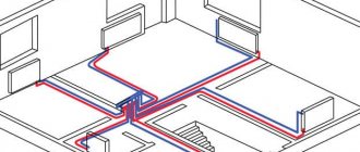
A distinctive feature of two-pipe wiring is that two lines are connected to each radiator. The coolant enters through the supply pipeline, the cooled water returns to the heating boiler through the return circuit.
Method of performing two-pipe wiring
Two schemes are used for pipe routing:
- "Star". Return and supply pipes go from a common manifold to each radiator. They branch into a number of parts identical to the number of heating devices.
- "Plume". The return and supply pipes go sequentially to the radiators. Devices located at a greater distance from the energy generator receive less heat.
The two-pipe configuration is designed with upper or lower heating distribution.
Two-pipe water heating circuit
Two-pipe top wiring
A system with top wiring involves circulation of coolant from top to bottom. It passes through the radiators and returns through the risers to the return pipeline and the heating boiler.
For natural circulation of liquid, it is necessary to ensure a slope of horizontal lines with a coefficient of 0.002-0.003. The system is fed into the return circuit from the water supply or by adding liquid to the expansion tank. When mixing cold water with a cooled coolant, the density of the solution increases and the pressure increases. To improve circulation, it is recommended to insulate the main riser.
Scheme of a two-pipe heating system with overhead wiring and natural coolant circulation
The expansion tank, which ensures self-regulation of the volume of liquid, is a mandatory design module with top wiring. It can be simple or complex.
A simple model is a container with two pipes: one of them is necessary to control the filling of the tank with liquid, the other acts as a supply riser in the heating system. The main disadvantages of a simple expander:
- it is necessary to check the water level in the container every 6-12 months;
- the housing needs insulation to prevent water from freezing in winter.
The complex design of the tank has 4 pipes: return and supply ensure circulation and minimize the risk of water freezing; two other elements control the fluid level. The method is characterized by highly automated processes, but is not popular due to complex installation and a large number of pipes that must be pulled through all floors. It is easier for the home owner to manually add water to the system 1-2 times a year.
Balancing a two-pipe heating structure is carried out by installing automatic or manual valves and gradually increasing the nominal diameter of the pipes from the boiler to the radiators. In a design with natural circulation of water, the hydraulic resistance should be less than the pressure.
Upper heating distribution is suitable for structures with an attic: a compensating tank for air removal should be located at the highest point of the structure.
Two-pipe bottom wiring
In a system with bottom wiring, the coolant moves from bottom to top. To use it, it is necessary to install a Mayevsky valve or another air vent, an automatic air vent.
In residential premises, lower wiring with natural coolant movement is rarely found. It requires a larger number of radiators, each of which must have an air bleeder installed. This results in the need to bleed the air every week. Banding the supply line with an air pipeline does not solve the problem. It erases all the advantages of the lower wiring and requires the installation of risers through all floors of the house.
To use the bottom wiring, you must introduce a pump into the circuit. In this case, it is characterized by the following advantages compared to the upper location of the highway:
- short length of pipeline in unheated rooms;
- reduction of non-productive energy losses;
- convenient shutdown of individual risers during repair work: valves are located in one place;
- aesthetic appearance: most pipes are hidden in the basement or in the floor structure.
The main advantage of the two-pipe configuration is the simple regulation of room temperature using an automatic or manual valve. When using a circulation pump, pipes of a smaller cross-section can be laid.
Key disadvantages compared to a single-pipe system:
- high cost and complexity of installation;
- a large number of connecting elements and pipes;
- the need to use additional valves to remove air.
It is advisable to use a two-pipe configuration in houses intended for permanent residence. When introducing a circulation pump, the scheme is suitable for buildings of any number of floors.
Design features
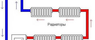
This CO is a closed circuit consisting of two branches along which the coolant moves. It is heated in a boiler plant. Next, along the supply branch (supply) of the pipeline, the heated water (brine, antifreeze) enters the heating devices (batteries, registers), thanks to which the air in the heated rooms is heated. Cooled water is discharged from all radiators into the return line (return), which is connected to the inlet of the boiler unit. The main differences are shown in the diagrams.
The main advantage is that with two-pipe heating, the temperature of the coolant remains practically unchanged.
Expert comment: There is a difference between the first and last batteries in the circuit, but it is quite insignificant and depends on the thermal conductivity of the pipeline from which the heating circuit is made.
The main disadvantage (which is always voiced by supporters of single-pipe heating) is the higher pipeline consumption, which means the higher estimated cost of the entire CO
Expert comment: The cost of a single-pipe heating system is not so small. Due to the sequential connection, as the coolant passes through each subsequent radiator, it cools down more and more. In order to obtain a sufficient amount of heat from the final radiators, it is necessary to increase the heat transfer area by increasing the number of battery sections. This is what increases the cost of single-pipe COs.
Horizontal systems (features)
This is a closed two-pipe system in which, instead of vertical risers, horizontal branches are laid, and a certain number of heating devices are connected to them. As in the previous case, branches can have upper, lower and combined wiring, only now this happens within the same floor, as shown in the diagrams:
As can be seen in the figure, a system with overhead wiring requires laying pipes under the ceiling of the premises or in the attic and will be difficult to fit into the interior, not to mention the consumption of materials. For these reasons, the scheme is used infrequently, for example, for heating basements or when the boiler room is located on the roof of the building. But if the circulation pump is correctly selected and the system is configured, then it is better to run the boiler pipe from the roof downwards, any homeowner will agree with this.
Combined wiring is indispensable when you need to install a two-pipe gravity system, where the coolant moves naturally due to convection. Such schemes are still relevant in areas with unreliable power supply and in houses of small area and number of floors. Its disadvantages are that there are many large-diameter pipes running through all the rooms, making them very difficult to hide. Plus the high material consumption of the project.
And finally, a horizontal system with bottom wiring. It is no coincidence that it is the most popular, because the scheme combines a lot of advantages and has almost no disadvantages. The connections to the radiators are short; the pipes can always be hidden behind a decorative screen or embedded in the floor screed. At the same time, the consumption of materials is acceptable, and from the point of view of work efficiency it is difficult to find a better option. Especially when a more advanced passing system is used, shown in the diagram below:
Its main advantage is that the water in the supply and return pipelines travels the same distance and flows in the same direction. Therefore, hydraulically, this is the most stable and reliable scheme, provided that all calculations are carried out correctly and installation features are taken into account. By the way, the nuances of systems with associated coolant movement lie in the complexity of the design of ring circuits. Often, pipes must cross doorways and other obstacles, which can increase the cost of the project.
Conclusion. For a private house, the best option is a two-pipe horizontal heating system with bottom wiring, but only in conjunction with artificial coolant circulation. If it is necessary to ensure energy-independent operation of thermal equipment and networks, then it is recommended to use one of the combined gravity systems - horizontal or vertical. The latter would be appropriate in a house with two floors.
Installation
Conventionally, several stages of work can be distinguished. First, the type of heating is determined. If gas is supplied to the house, then the most ideal option would be to install two boilers: one gas, the second a spare, solid fuel or electric.
Next, you should agree on the installation of the heating system in the project documentation and begin purchasing the necessary materials, devices, and preparing tools.
Stages
Briefly, installation consists of the following points:
- a supply pipe is led upward from the boiler and connected to a compensating tank;
- a pipe from the upper line is removed from the tank, which goes to all radiators;
- a bypass (if provided) and a pump are installed;
- the return line is drawn parallel to the supply line, it is also connected to the radiators and cut into the boiler.
Boiler
For a two-pipe system, the boiler is installed first, for which a mini-boiler room is created. In most cases, this is a basement (ideally a separate room). The main requirement is good ventilation. The boiler must have free access and be located at some distance from the walls.
The floor and walls around it are lined with fire-resistant material, and the chimney is vented to the street. If necessary, a circulation pump, distribution manifold, control and measuring instruments are installed near the boiler.
Radiators
They are installed last. They are located under the windows and fixed with brackets. The recommended height from the floor is 10–12 cm, from the walls – 2-5 cm, from the window sills – 10 cm. The inlet and outlet of the battery is fixed with shut-off and control devices.
It is advisable to install temperature sensors - with their help you can monitor temperature indicators and regulate them.
Design and principle of operation
Any water CO is based on heat exchange between the coolant (water, brine, antifreeze), which circulates along the circuit, and the air of the heated room. Depending on the architecture of the heated room, there are two options for supplying water to the radiators: through sun loungers (horizontal main pipeline) and vertical risers.
The principle of operation of a horizontal single-pipe heating system is as follows: the coolant circulates in the main pipe, forming a closed loop that begins and ends in the heat generator. It is to one main line that all the equipment necessary for CO operation is connected.
Pros of the system
The disadvantage of the system is its higher cost due to the number of materials and parts.
Two-pipe structures are more complex than when using a single pipe. At the same time, they are becoming the most popular method of heating private and apartment buildings. Positive features:
- The water temperature for each section of the circuit is the same.
- Each battery can be adjusted. The owner can install thermostats on different radiators and adjust the device to the desired temperature. This will not affect the heat transfer of the remaining batteries in the house.
- Minimal pressure loss. Thanks to this property, a low-power circulation pump can be used.
- The system continues to function even after one of the batteries fails. When carrying out repair work, you do not need to turn off the heating in the entire house.
- Can be installed in a building with any number of floors and different areas.
(no votes yet)
General disadvantages of a two-pipe system
- Large design due to a line of 2 pipes.
- More complex installation
- The cost is slightly higher than a single-pipe system.
- Aesthetically less attractive than a single-pipe system, if you do not hide the pipeline in a screed or decor.
