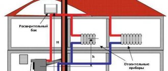
When operating heating systems with natural coolant circulation, owners of apartments and private houses are often faced with the problem of insufficient heating of radiators installed in remote rooms.
It all depends on the length of the heating circuit. If its length is more than 30 meters, the level of water pressure becomes insufficient to maintain the required temperature at its most distant points.
To achieve stable operation of the equipment, devices are used that ensure rhythmic circulation of the coolant. Preliminary calculation of a pump for a heating system makes it possible to determine the parameters necessary to select the most optimal model.
Why are calculations needed?
Most modern autonomous heating systems, used to maintain a certain temperature in residential premises, are equipped with centrifugal pumps that ensure uninterrupted circulation of liquid in the heating circuit.
By increasing the pressure in the system, it is possible to reduce the temperature of the water at the outlet of the heating boiler, thereby reducing the daily consumption of gas consumed by it.
The correct choice of the circulation pump model allows you to significantly increase the level of equipment efficiency during the heating season and ensure a comfortable temperature in rooms of any size.
What you need to know to calculate power
To understand the algorithm for calculating a circular pump, it is necessary to start from some parameter, the accuracy of which cannot be doubted. To do this, you need to open the technical passport of the room in which you plan to install an autonomous heating system and find out its area. For example, let’s take a separate building (private house) with an area of 300 m².
The next step is to determine the quantities needed for the calculation.
You need to know three main parameters:
- Qn —heat source power (kW);
- Qpu is the performance of the circulation pump, an indicator of the volumetric supply of coolant for the type of room we have chosen (m³/hour);
- Hpu is the pressure power required to overcome the hydraulic resistance of the system (m).
Calculation of heat source power (AOGV)
For each room, depending on its area or volume, there are certain technical standards for the power of the heating source.
To calculate this parameter we use the following formula:
Qn = Sn × Qsp ÷ 1000
| Designation | Parameter | Units |
| Qn | heat source power | kW |
| Sn | heated area | m² |
| Qsp | specific heat demand of the room | W/m² |
We know the area of the heated room (300 m²), and the second indicator depends on the type of structure: if it is an apartment building, then its value is 70 W/m², in our case (a separate building), it will be 100 W/m².
Let's plug these values into the formula and see what we get:
300 × 100 ÷ 1000 = 30 kW.
So, the power of the heating unit for our room was 30 kW. There is another method for determining this value.
The volume of the heated room and the power of the heating unit can be found in the following table.
| Thermal power | Room volume new house (m³) | Room volume old house (m³) |
| 5 kW | 70 – 150 | 60 – 110 |
| 10 kW | 150 – 300 | 130 – 220 |
| 20 kW | 320 – 600 | 240 – 440 |
| 30 kW | 650 – 1000 | 460 – 650 |
| 40 kW | 1050 – 1300 | 650 – 890 |
| 50 kW | 1350 – 1600 | 900 – 1100 |
| 60 kW | 1650 – 2000 | 1150 – 1350 |
Let me remind you that the volume of a room is equal to the product of its area and height.
(V = S × h), where:
- V is the volume of the room;
- S - heated area;
- h is the height of the rooms.
In our case, with a ceiling height of 2.5 m, it will be:
300 × 2.5 = 750 m³
We look for this indicator in the second column of the table and get the same 30 kW.
Calculation of pump performance
Correct calculation of pump power allows you to provide the heating system with the required amount of coolant at any point. Having determined the technical characteristics of the heating boiler, we can calculate the performance of the circulation equipment sufficient for our premises.
Let's use the following formula:
Qpu = Qn ÷ kτ × Δt
| Designation | Parameter | Units |
| Qpu | pump performance | m³/hour |
| Qn | heat source power (AOGV) | kW |
| kτ | liquid heat capacity coefficient | — |
| Δt | temperature difference at the system inlet and outlet | ⁰С |
If water is used as a coolant, its specific heat capacity is 1.164. If a different liquid is used, then the value of this parameter must be looked up in the corresponding tables.
With a functioning heating system, the value of the temperature difference (Δt) can be calculated by the method of elementary subtraction of indicators taken from measuring instruments installed at the input and output of the system (Δt = t1 – t2, where t1 is the temperature at the inlet of the heating circuit, and t2 is the temperature at the outlet from him).
Otherwise, you will have to use standard indicators. The temperature difference at the inlet and outlet of the system (Δt) ranges from 10-20 ⁰С.
Let's take the average value - 15 ⁰С and substitute the results obtained into the formula:
Qpu = 30 ÷ 1.163 × 15 = 1.72 m³/hour
Now one of the technical characteristics of the circulation pump is known.
Calculation of the required power (height) of pressure
The power of the heating boiler and the performance of the pump are known; the next step is to determine the coolant pressure sufficient to overcome the internal hydraulic resistance of the pipes and elements of the heating system.
To do this, the heat losses on the longest section of the circuit are taken into account - from the heat source to the distant radiator. To deliver heat to any point, the pressure power of the supplied liquid must be higher than the total hydraulic resistance of all heating devices.
The heating pump pressure is calculated using the following formula:
Hpu = R × L × ZF ÷ 10000
| Designation | Parameter | Units |
| Hpu | Power (height) of pressure | m |
| R | Losses in supply and return pipes | Pa/m |
| L | Heating circuit length | m |
| ZF | hydraulic coefficient resistance of shaped and shut-off valves of the system | — |
Depending on the diameter of the pipes, the value of the parameter R is in the range of 50–150 Pa/m (the minimum value is applicable for water supply systems with a pipe diameter of 2 inches and above; for modern plastic and metal pipes the losses are 150 Pa/m). For our premises it is necessary to use the maximum value.
If the exact length of the circuit (L) is difficult to determine, this parameter is calculated based on the dimensions of the heated room. The length, width and height of the house are added and then doubled. With a total area of 300 m², we can assume that the length of the house is 30 m, the width is 10 m, and the height is 2.5 m. In this case, L = (30 + 10 + 2.5) × 2, that is, 85 meters.
The simplest option for determining the ZF value is as follows: if there is no thermostatic valve in the system, it is equal to 1.3, and if it is present, it is 2.2.
To calculate, take the maximum value of this coefficient and substitute all the obtained values into the formula:
150 × 85 × 2.2 ÷ 10000 = 2.8 m.
The proposed calculation method is not the only one. To more accurately determine the pressure indicators of the pump, there are formulas that take into account not the loss coefficient, but the real values of these indicators.
Hydraulic resistance
This term expresses the total pressure loss in the system. The heating circuit consists of individual elements, each of which has its own value for this characteristic.
These include:
- valves;
- valves;
- filters;
- measuring and control instruments;
- radiators;
- convectors, etc.
To accurately determine losses in the system, the values specified in the technical documentation for each component of the heating circuit are usually used.
If this is not possible, you can find this information in the following table:
| System element | Pressure loss | Units |
| Boiler | 1000 – 5000 | Pa |
| Compact boiler | 5000 – 15000 | Pa |
| Heat exchanger | 10000 – 20000 | Pa |
| Heat meter | 15000 – 20000 | Pa |
| Water heater | 2000 – 10000 | Pa |
| Heat pump | 10000 – 20000 | Pa |
| Radiator | 500 | Pa |
| Convector | 2000 – 20000 | Pa |
| Radiator valve | 10000 | Pa |
| Control valve | 10000 – 20000 | Pa |
| Check valve | 5000 – 10000 | Pa |
| Filter (clean) | 15000 – 20000 | Pa |
| Thermostatic valve | 5000 – 10000 | Pa |
| Mixer | 2000 — 4000 | Pa |
In this case, to calculate the head height it is convenient to use a slightly different formula.
H = 1.3 × (R1L1 + R2L2 + Z1 + Z2 + .... + Zn) ÷ 10000, where:
- R1, R2 – losses in the supply and return pipes (Pa/m);
- L1, L2 – length of supply and return pipeline lines (m);
- Z1, Z2 ... Zn – pressure loss on individual elements of the system (Pa).
The number in the denominator of the formula (10000) is the conversion factor from Pascals to meters.
Choosing a pump
Once all the necessary parameters for purchasing a circulation pump have been determined, you can begin to select a specific model. The technical characteristics of devices of this type are reflected in the graphs of the relationship between device performance and pressure height, attached to their passport. This data can be easily found on the Internet.
Depending on the number of velocities in the coordinate system, one, two or three graphs are constructed indicating the point of the optimal relationship between these quantities. We plot the pump performance value on the X axis, and the height of its pressure on the Y axis. The intersection point of these parameters should be as close as possible to the point indicated on the graph - their complete combination would be ideal.
The most common models have a three-speed operating mode. If you choose one of them, then the selection of characteristics must be carried out according to the schedule corresponding to the second speed, that is, the average. In other cases, the parameters are combined using any of them.
Prices for different models of pumps for the heating system
heating pump
How to calculate a pump if the boiler power is known
Situations often arise when a boiler is purchased in advance or a pump is added to an already functioning heating system. In this case, the power of the heating unit is known, and all other elements of the circuit are selected depending on the value of this indicator.
To calculate the performance of the circulation pump at a given power of the heating source, use the following formula.
Q = N ÷ (t2 - t1), where:
- Q – pump capacity (m³/hour);
- N – power of the heating device (W);
- t2 – coolant temperature at the system inlet (⁰С);
- t1 – liquid temperature at the outlet of the circuit (⁰С).
If it is not possible to accurately determine the specified supply and return parameters, use the average temperature difference - 15 ⁰C.
Determining pump performance
If you calculate the circulation pump of the heating system correctly and accurately, this will provide the room with the correct distribution of heat when all areas are heated evenly and without differences. After identifying all the technical parameters of the heating boiler, it will be possible to begin calculating the efficiency of the pump movement; it should be sufficient for the room. There is a formula that needs to be used to calculate the pump performance, Qpu=Qn/kt* δ t:
- Qpu is the performance of the circulation pump;
- Qn is the thermal power of the equipment;
- kt is the heat capacity coefficient of the liquid;
- δ t is the temperature difference that forms at the outlet and input of the entire system.
In cases where water is responsible for the functions of the coolant, its specific total heat capacity will be 1.164. When a liquid other than water is used, the values must be looked up in the formulas. With complete proper circulation and operation of the space heating system, the temperature difference, which is denoted as δ t, is calculated using the usual method of subtracting some indicators that were obtained from the measuring instruments that were placed at the outputs and inputs. The formula is as follows: δ t is equal to t1-t2, while t1 is the temperature located at the level near the input of the circuit, and t2 is the temperature at its output. In other situations, you will need to use regular metrics. Typically, the temperature between the inputs and outputs varies and is ten to twenty degrees Celsius. For example, let’s take the average temperature of this period, 15 degrees, and substitute this value into the existing formula. Qpu=30/1.163*15=1.72 cubic meters per hour.
Number of pump speeds
By its design, a circulation pump is an electric motor mechanically connected to the shaft of an impeller, the blades of which push the heated liquid out of the working chamber into the heating circuit line.
Depending on the degree of contact with the coolant, pumps are divided into devices with a dry and wet rotor. In the former, only the lower part of the impeller is immersed in water, while in the latter, the entire flow passes through itself.
Models with a dry rotor have a higher coefficient of performance (efficiency), but create a number of inconveniences due to noise during operation. Their analogues with a wet rotor are more comfortable to use, but have lower performance.
Modern circulation pumps can be operated in two or three speed modes, maintaining different pressures in the heating system. Using this option makes it possible to quickly warm up the room at maximum speed, and then select the optimal operating mode and reduce the energy consumption of the device by up to 50%.
Speed switching is carried out using a special lever mounted on the pump body. Some models have an automatic control system that changes the engine speed in accordance with the air temperature in the heated room.
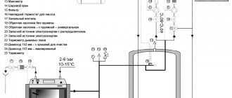
Pump design and technical parameters
The design of the equipment includes a housing to which the volute is connected, and circuit pipes to the volute. The housing is equipped with an electric motor with a control board and terminals to connect the electrical wires. To move water along the system's main lines, a rotor with an impeller is used: with its help, water is sucked in on one side, and on the other side it is pumped into the pipes of the circuit.
The circulation pump should be selected based on the following technical parameters:
- Device performance (flow) - represents a volumetric value numerically equal to the maximum volume of water pumped through the device in one hour.
- Pressure - represented by the maximum value of hydraulic resistance exerted by all elements of the heating circuits in relation to the movement of the coolant, and capable of being overcome by the pump. Measured in meters.
- Device characteristic – represents a production value that determines the relationship between the pressure of the device and its performance.
Useful tips
When choosing a pump for a heating system, preference should be given to designs with a “wet” rotor, since they operate very quietly and withstand higher loads than hydraulic devices of other modifications.
In addition, pay attention to the material of the case - opt for products made of stainless steel, bronze or brass. Preference should also be given to models with bearings and shafts made of ceramics. The service life of such equipment exceeds 20 years.
When installing the device into the system, it is necessary to ensure that the impeller shaft is positioned horizontally, that is, parallel to the pipe. If a suspicious noise appears during operation of the pump, this does not indicate a malfunction or a manufacturing defect. Try bleeding the air remaining in the system after starting.
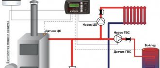
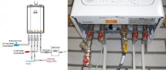
Circulation pump installation location
When installing the pump, it is important to provide free access for its maintenance. It is optimal to install the equipment on the return line in front of the boiler. This contributes to:
- uniform supply of feed water to the system;
- on less hot water the pump will work longer;
- no air pockets will be created in the boiler.
The pump impeller is installed horizontally and operates under the fill.
The pump is mounted only on a bypass, which must have a cross-section smaller than the main line with the obligatory inclusion of a check valve. This will ensure the coolant circulates along the main line in the absence of electricity. The bypass must be cut off to allow repair of the pump.